

DTL Broadcast Routemaster 5SV2975F 16x1, Routemaster 5SV2975 16x1 User Manual

DTL Broadcast Ltd
Johnson’s Estate
Silverdale Road
Hayes
Middx UB3 3BA, UK.
Phone: +44 (0) 20 8813 5200

Fax: +44 (0) 20 8813 5022
Email: info@dtl-broadcast.com
Internet: www.dtl-broadcast.com

Cont ents
\\Dtlserv er\company \PRODUCTS\Ro utemaster\Rou temaster User's Guid e Iss4 .1.d oc Co ntents - 1
Routemaster Range User’s Guide
Please note the contents list covers modules currently available in the range.
Your User’s Guide may only include relevant sections.
1 G eneral
1.1 Introduction
1.2 Overview of the range
1.3 Safety and pre-installation checks
1.4 Warranty
2 Video matrices
2.1 16x1 video matrices
2.2 16x4 video matrices (1U)
2.3 16x4 & 16x8 video matrices (2U)
2.4 5x1 component matrix
3 Audio matrices
3.1 16x1 mono & stereo matrices
3.2 16x4 audio matrices
3.3 16x8 audio matrices
4 Control
4.1 Sample systems
4.2 Button per cross-point panels
4.3 XY panel
1 General
Issue 4 Pa ge 1 - 1
1.1 Introduction
This User’ s Guide provides information on installing and operating Routemaster
systems.
Section 1.3 ‘ Safety and Pre-installation checks’ includes instructions which must
be followed.
Whils t every effo rt has been made to ensure th e accuracy o f this g uid e, DTL
Broadcast Ltd cannot be held responsible for errors or omissions. We would of
course welcome any constructive feedback.
1.2 Overview of the range
The Routemaster range comprises a series of analogue video and audio routing
matrices and associ ated con trol o pti ons. As st andard, models are availab le in s izes
from 16x1 through to 16x8. Various control options are available with local and
remote button per cross-point and XY panels.
1.3 Safety and Pre-Installation checks
Safety warning
Before connecting the mains power supply, please ensure that the equipment is set
for the correct local voltag e. Unless o therw ise reques ted, all Rou temasters are
delivered set to operate on 230 VAC.
Mains vo ltag es may be accessib le if the co vers are removed from the unit . Covers
should only be removed when equipment is not connected to the mains and by
qualified service engineers.
Pre-Inst allati on check s

1 General
Issue 4 Pa ge 1 - 2
On unpacking the equipment please check for any signs of transit damage. If any is
found contact your carriers immediately as they may wish to inspect the equipment
as well as the pack aging .
If all appears well check the eq uip men t agains t the packin g/deli very not e for any
errors or omissions. If there are any please contact your distributor or local agent
unless we have supplied you directly.
1.4 Warranty
DTL Broadcast Ltd (the company) supplied products are warranted against defects
in materials and workmanship for a period of one year from the date of shipment. At
its option, the company will repair or replace p roducts that prove to be defective
during the warranty period, provided they are returned to the company with
advance notification freight prepaid. The company will continue to support these
products after expiration of the warranty.
When a dealer supplies the company’s products, that dealer should be approached
initially if there are any warranty problems.
The company makes no other warranties, express or implied, as to the
merchantability, fitness for a particular purpose, or otherwise. The company’s
liability for any cause, including breach of cont ract, breach of warranty , or
negligence, with respect to products sold by it, is limited to repair or replacemen t
by the company, at its sole discretion. This remedy is exclusive.
In no event shall the company be liable for any incidental or consequential
damages, including loss of profits.
2 Video matrices
Issue 4 Pa ge 2.1 - 1
2.1 16x1 video matrices
Features
The 16x1 Routemaster video matrix is a proven unit designed with a variety of
options to allow it to be easily installed, used and integrated into existing and
future systems. (The 5SV2987 & 5SV2987F YUV/RGB component video matrices
comprise three 1 6x1 composi te mat rices married t ogeth er.)
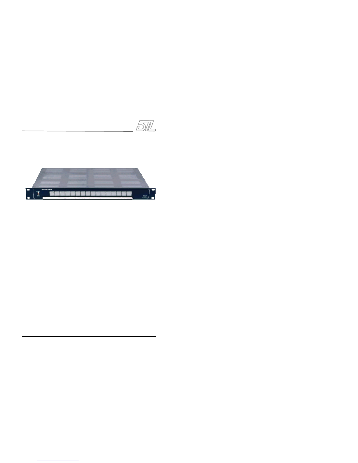
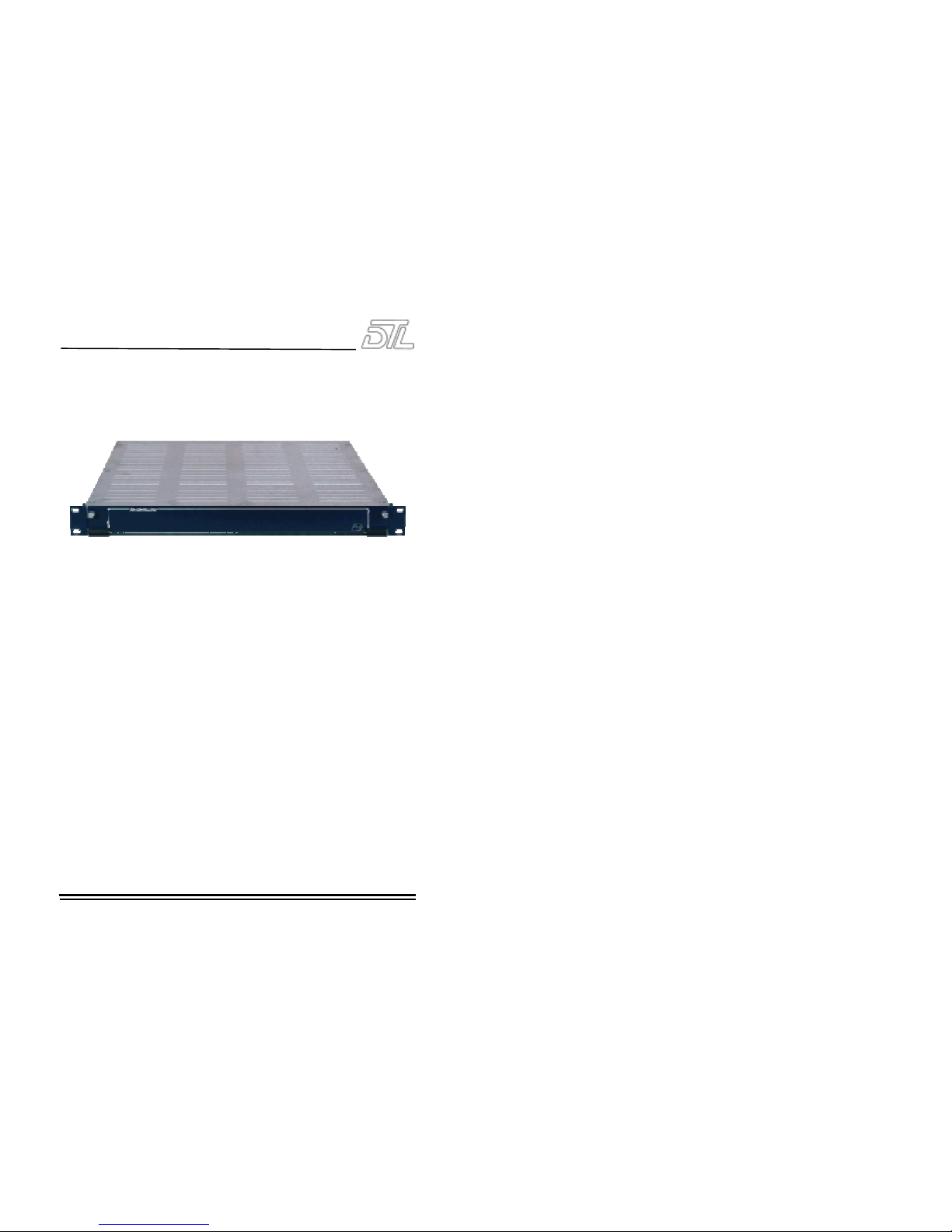
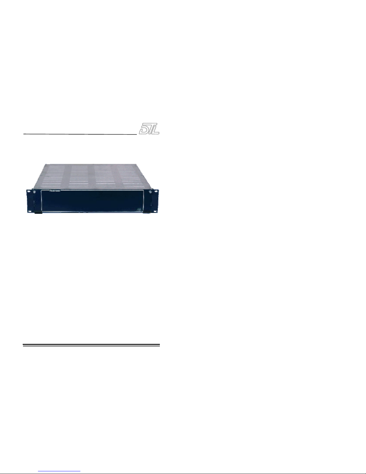
• The 5SV2975F 16x1 video routing matrix has a front panel mounted button per
cross-point control panel.
• The 5SV2975 16x1 video routing matrix has no integral control panel.
• Switching is within the vertical interval.
• 1U rack mounting units with looping inputs and dual outputs.
• Full broadcast quality.
• Control can be local and/or remote with button per cross-point (and/or XY
panels) using the reliable and proven Routemaster BCD system.
• Can be married to other video levels for component (YC, YUV, RGB or RGBS)
operation and to audio units for audio follow video with breakaway available
dependant on the type of control panel fitted.
2 Video matrices
Issue 4 Pa ge 2.1 - 2
Installation
Please read sectio n 1.3 ‘ Safety and P re-Instal latio n checks ’ before pro ceeding .
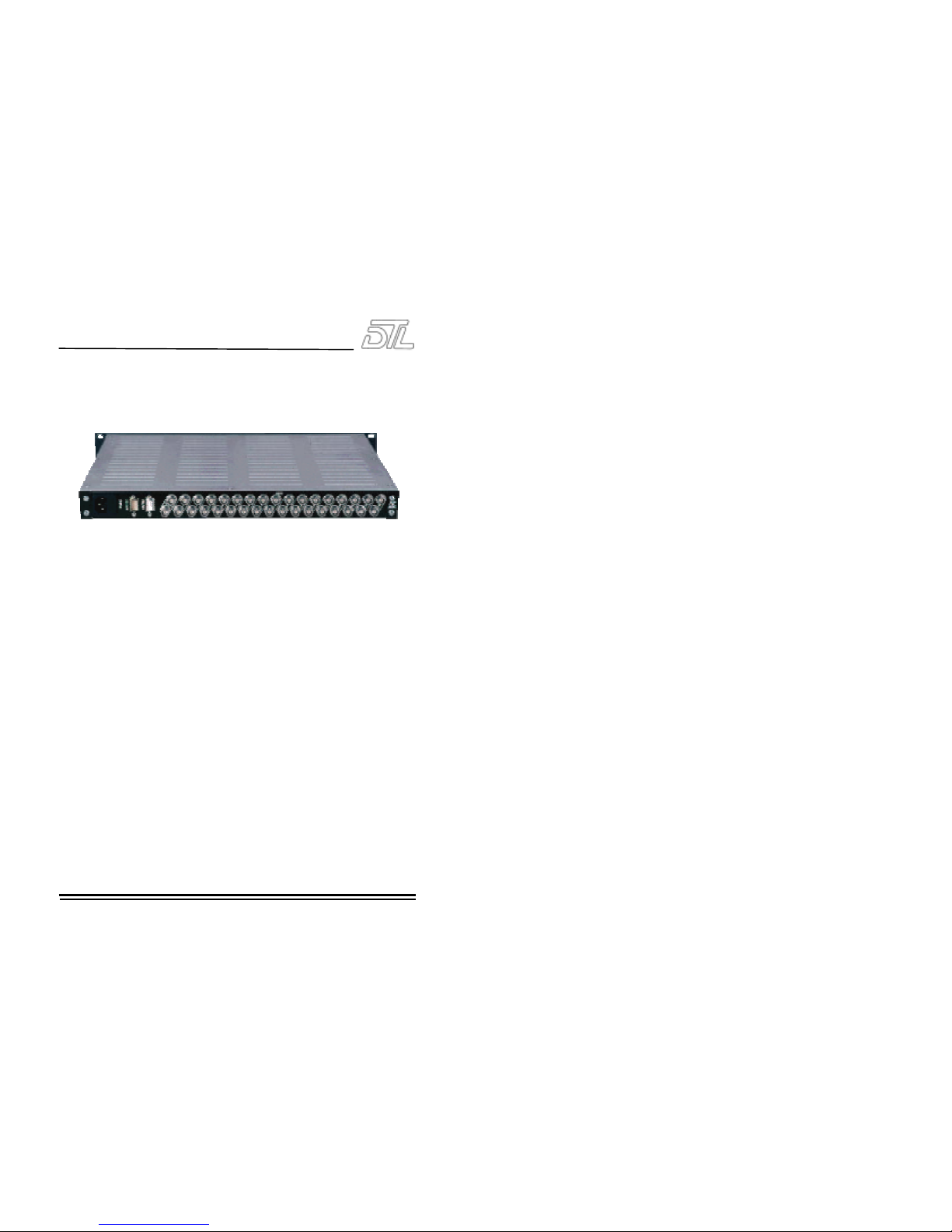
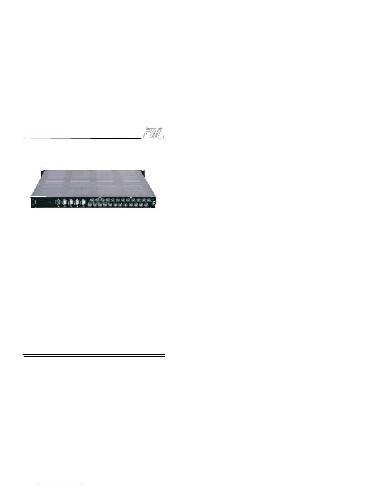
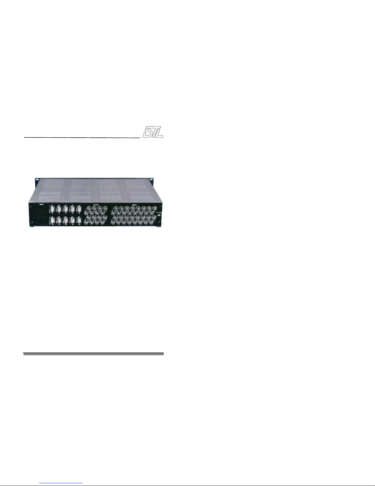
For a single level matrix with local control simply connect the video inputs and
outputs as shown on the rear panel (terminating any unused BNC’s at 75Ω),
connect the mains mating IEC connector to a suitable 230v supply (NB Earth
MUST be connect ed at all times) and t he mat rix is read y fo r use.
When a s ystem requ ires a number o f Ro utemaster matrices to be permanent ly
married (e.g. video and audio, video and stereo audio, component video and
audio), connect the married cable between the units being operated together with
the 4C014 married cable supplied (if not supplied see ‘connection for married
operation’ below).
For units with remote control connect the appropriate Routemaster(s) to the
control panel with the control cable(s) supplied.
NB When video and audio Routemaster(s) are permanently married, the video acts
as the master. Control panels should be connected to the video unit. When
matrices are married for component video, ensure that control panel(s) are
connected to th e Y/G matrix so that syncs are derived correctly .
Section 4.2 covers the 5S2935 16 button per cross point control panel and
section 4.3 the 5SX4100 XY control panel.
2 Video matrices
Issue 4 Pa ge 2.1 - 3
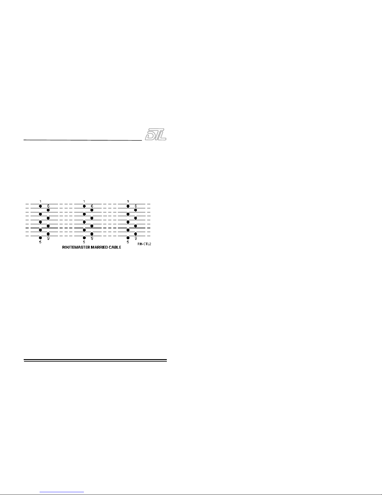
Connection for married operation:
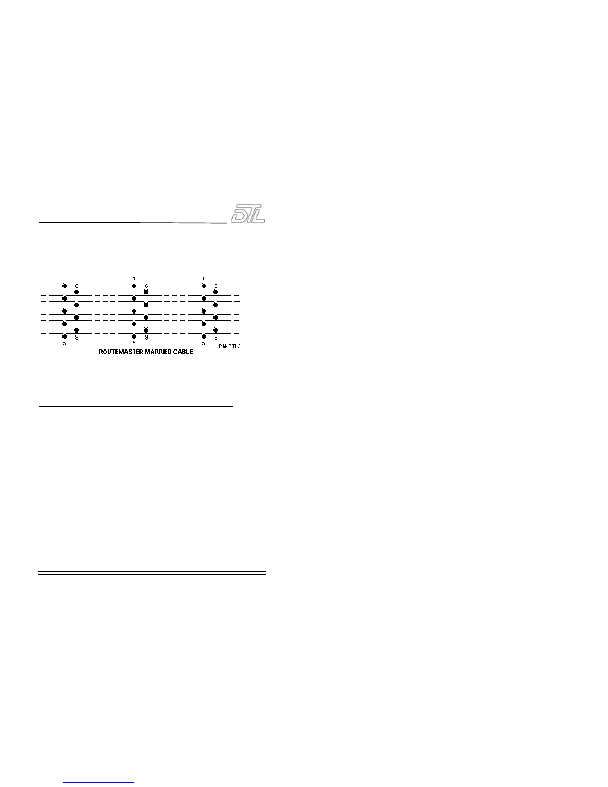
Connect all units in daisy-chain fashion via the 9 way ‘D’ type male connector at
the rear of the unit using 4C014 married cable or a cable made up of ‘D’ type
female connectors connected in parallel as below. When a video and audio
Routemaster(s) are married, the vid eo un it acts as the master. Remote or local
control should be connected to the video unit. If being married to other
component levels ensure the unit designated Y/G is connected appropriately so
that sync is derived from the correct level.
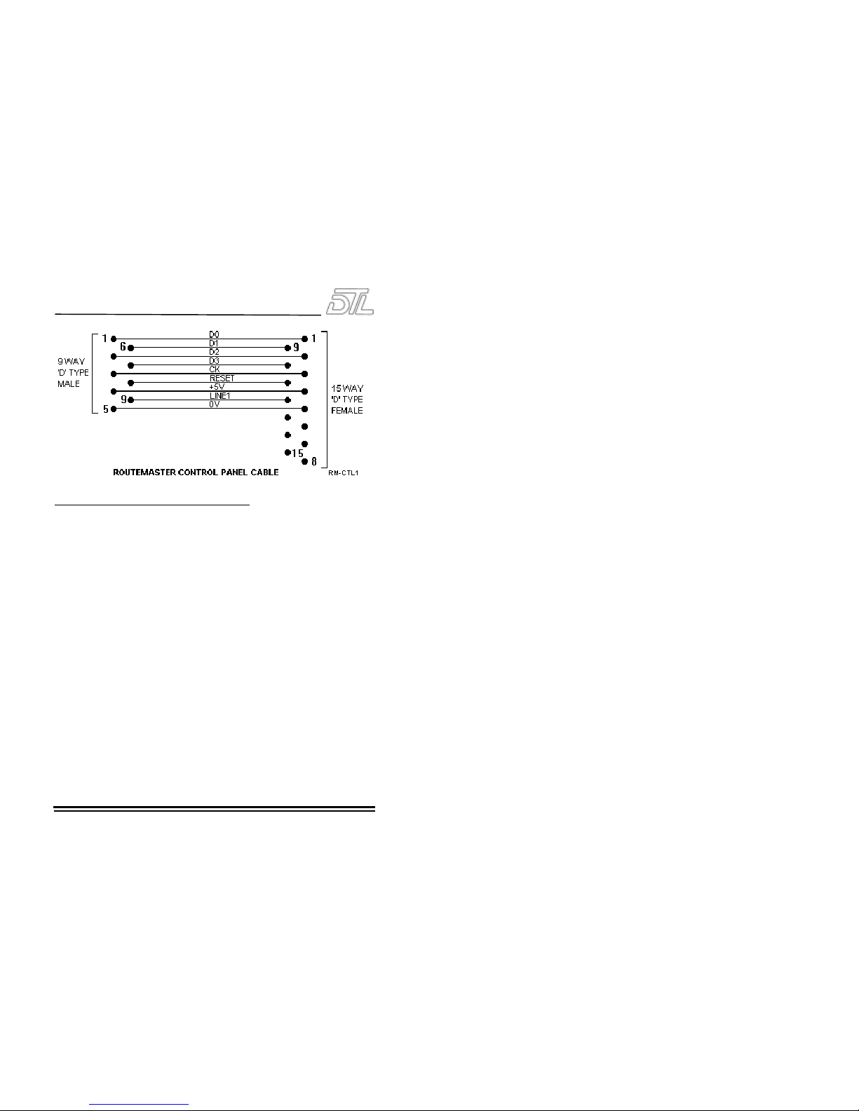
Connection for remote control:
16x1 Routemasters can have local and/or remote control. 5S2925 16 button-percrosspoint panels are normally used for remote control. (If the XY remote control
panel is being used, please refer to section 4.3.)
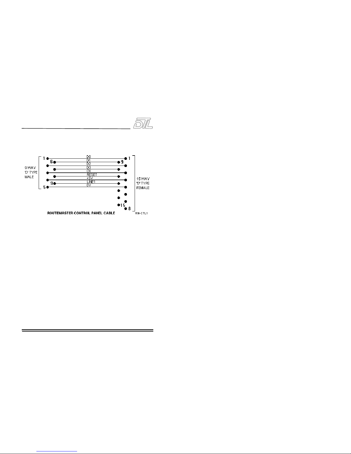
Control panels are connected to 16x1 Routemasters using the female 9 way ‘D’
type connector on the rear of the unit. Use control cable 4C009, which is available
in a variety of lengths from 10 to 50 metres. (Alternatively a control cable can be
made from a 9 way ‘ D’ type male and 15 way ‘D’ type female using the
connections given below. Note that screened cable must be used, with the screen
connected to the shell of the ‘D’ type connectors at both ends to meet EMC
requirements.)
For more complex married systems with multiple levels of video and/or audio, the
remote control panel should be connected to the composite video matrix (or the
Y/G matrix for component video).
2 Video matrices
Issue 4 Pa ge 2.1 - 4
Altogether 4 button-per-crosspoint panels can be used to control a 16x1, (3
remotes if local control is fitted) each pan el with a uni que prio rity level (see
5S2935 Control Panel section).
Operation
Selecting a source on the front panel or on a remote button per cross-point panel
switches the output to that source so long as the slider switch on the control
panel is in the enable position. (When the slider switch is in the disable position
tallies are still shown.)
When initially powered the matrix defaults to input 1. With local and remote
control panels operation is prioritised. The local control panel has priority level 2
whilst remote panels can be set for priority levels 1, 3 or 4, where level 1 has the
highest priority. The sliding switch, however may be used to disable selection by
one of the panels (but tallies will still be shown).
Specif icatio ns
Inputs 16 with loop through
Outputs 1
Feeds per output 2
Switching Vertical interval
Control data BCD
Video level 1V p-p ±3dB
Maximum input DC ±2V
Maximum output DC Black level var ±20mV
Input return loss <-52dB @ 15KHz

2 Video matrices
Issue 4 Pa ge 2.1 - 5
<-46dB @ 4.43MHz
Output return loss <-46dB @ 15KHz
<-40dB @ 4.43MHz
Frequency response ±0.1dB @ 6MHz
-0.5dB @ 10MHz
2T pulse & bar 0.2%K
2T bar 0.2%K
2T pulse 0.2%K
50Hz square wave 0.2%K
Differential phase 0.1º
Differential gain 0.1%
Luminance non-linearity 0.1%
Delay inequality ±1ns
Gain inequality ±0.5%
Crosstalk <-60dB @ 4.43MHz
Noise luminance weighted <80dB RMS
Timing spread ±1º @ 4.43MHz
Electrical length Typical 25ns
Video connectors 75Ω BNC
Control panel connectors 9 way D type socket
Married connector 9 way D type plug
Power connector IEC
Power 230VAC 50Hz
Temperature range 0-40ºC
Height 44mm (1U)
Width 483mm (19”)
Depth 360mm
Weight 5SV2975F 4.8kg - 5SV2975 4kg
Ordering inf ormati on
5SV2975F 16x1 video matrix with front panel button per cross-point
control and with looped through inputs and dual outputs
1U
5SV2975 16x1 video matrix with looped through inputs and dual
outputs
1U
5SV2987F 16x1 YUV/RGB component video matrix with front panel
button per cross-point control and with looped through
inputs and dual outputs
3U
5SV2987 16x1 YUV/RGB component video matrix with looped
through inputs and dual outputs
3U

2 Video matrices
Issue 4 Pa ge 2.1 - 6
4C014 Married cable (for use with 2 or more matrices)
5S2935 16 button per cross-point panel 1U
4C009 Control cable for 5S2935&8 10m
4C009/15 Control cable for 5S2935&8 15m
4C009/20 Control cable for 5S2935&8 20m
4C009/25 Control cable for 5S2935&8 25m
4C009/30 Control cable for 5S2935&8 30m
4C009/35 Control cable for 5S2935&8 35m
4C009/50 Control cable for 5S2935&8 50m
5SX4100 XY remote control panel 1U
4C025/25 Control cable for 5SX4100 25m
4C025/50 Control cable for 5SX4100 50m
2 Video matrices
Issue 4 Pa ge 2.2 - 1
2.2 16x4 video matrices (1U)
Features
5SV2976 16x4 video ma trix
The 5SV2976 16x4 Routemaster video matrix is a proven unit designed with a
variety of options to allow it to be easily installed, used and integrated into
existing and future systems. (The 5SV2978 YUV/RGB video matrix comprises
three 5SV2976 composite matrices married together.)
• Switching is within the vertical interval.
• 1U rack mounting matrix
• Terminating inputs and dual outputs (a 2U variant with looping inputs is also
availabl e).
• Full broadcast quality.
• Designed for remote control with button per cross-point and/or XY panels
using the reliable and proven Routemaster BCD system.
• Can be married to other video levels for component (YC, YUV, RGB or RGBS)
operation and to audio units for audio follow video with break-away available
dependant on the type of control panel fitted.
2 Video matrices
Issue 4 Pa ge 2.2 - 2
Installation
Please read sectio n 1.3 ‘ Safety and P re-Instal latio n checks ’ before pro ceeding .
For a single level matrix, connect the video inputs and outputs as shown on the
rear panel (terminating any unused BNC’s at 75Ω) then conn ect the mains mati ng
IEC connector to a suitable 230v supply (NB Earth MUST be connected at all
times).
For multiple levels connect the married cable between the units being operated
together with the 4C014 married cable supplied (if not supplied see ‘connection
for married operation’ below). If being married to other component levels ensure
the unit designated Y/G is connected appropriately so that sync is derived from
the correct l evel.
For units with remote control connect the appropriate Routemaster(s) to the
control panel(s) with the control cable(s) supplied. NB When video and audio
Routemaster(s) are married, the vid eo acts as the master. Remo te or local cont rol
should be connected to the video unit. If control cables are not supplied see
‘connection for remote control below.
Connection for married operation:
Connect all units in daisy-chain fashion via the 9 way ‘D’ type male connector at
the rear of the unit using 4C014 married cable or a cable made up of ‘D’ type
female connectors connected in parallel as below. When a video and audio
Routemaster(s) are married, the vid eo un it acts as the master. Remote or local
2 Video matrices
Issue 4 Pa ge 2.2 - 3
control should be connected to the video unit. If being married to other
component levels ensure the unit designated Y/G is connected appropriately so
that sync is derived from the correct level.
Connection for remote control:
16x4 video Routemasters can be controlled by a 5S2935 button-per-crosspoint
control panel for each o utpu t, by th e 5SX4100 XY panel or by a mixture of both.
When using only the 5S2935 16 button-per-crosspoint control panels
Control panels are connected to 16x4 Routemasters using the female 9 way ‘D’
type connector on the rear of the unit. Use control cable 4C009, which is available
in a variety of lengths from 10 to 50 metres. (Alternatively a control cable can be
made from a 9 way ‘ D’ type male and 15 way ‘D’ type female using the
connections given below. Note that screened cable must be used, with the screen
connected to the shell of the ‘D’ type connectors at both ends to meet EMC
requirements.)
For more complex married systems with multiple levels of video and/or audio, the
remote control panels should be connected to the composite video matrix (or the
Y/G matrix for component video).
Altogether 4 button-per-crosspoint panels can be used to control any one output,
each panel w ith a u niqu e priori ty lev el (see 5 S2935 Control Panel section 4.2).
2 Video matrices
Issue 4 Pa ge 2.2 - 4
When using only the 5SX4100 XY control panels
A splitter cable (specific to your particular requirement) is supplied with each
system. This should be connected to the 16x4 Routemaster(s) as shown by the
labels on its connectors and to the socket marked PL1 on the rear of the XY panel
using control cable 4C025, which is available in a variety of lengths from 10 to 50
metres. (Alternatively a control cable can be made from a 25 way ‘D’ type male to
25 way ‘D’ type male with pin to pin connections. Note that screened cable must
be used, wi th the screen con nected t o the s hell o f th e ‘D’ typ e connect ors at b oth
ends to meet EMC requirements.)
.
For the simplest system when an XY panel only controls a single 16x4 video
matrix, the splitter cable has four 9 way ‘D’ type male connectors which connect
to the four control sockets on the rear of the matrix, and a 25 way ‘D’ type female
connecto r for t he cabl e to th e XY panel.
When a number of matrices are being used for different levels of video and/or
audio, the splitter cable also includes 9 way ‘D’ type female connector(s) to
connect to the ‘married’ sock ets on the rear o f each matrix (as s hown by the labels
on the connectors).
When 5S2935 16 button-per-crosspoint control panels are being used in addition
to an XY panel, the splitter cable also has 9 way ‘D’ type female connectors for
connecting 4C009 control cables to the button-per-crosspoint panels. (See the
previous ‘When using only the 5S2935 16 button-per-crosspoint control panels’
section for fuller details on connecting these panels.)

2 Video matrices
Issue 4 Pa ge 2.2 - 5
Section 4.2 contains details on the 5S2935 16 button-per-crosspoint control
panels and section 4.3 details on the XY panel.
Operation
The 16x4 Routemaster is controlled remotely using button-per-crosspoint and/or
XY control panels. Section 4.2 contains full details on operating the 5S2935 16
button-per-crosspoint control panels and section 4.3 full details on operating the
XY panel.
Specif icatio ns
Inputs 16 terminating
Outputs 4
Feeds per output 2
Switching Vertical interval
Control data BCD
Video level 1V p-p ±3dB
Maximum input DC ±2V
Maximum output DC Black level var ±20mV
Input return loss <-52dB @ 15KHz
<-46dB @ 4.43MHz
Output return loss <-46dB @ 15KHz
<-40dB @ 4.43MHz
Frequency response ±0.1dB @ 6MHz
-0.5dB @ 10MHz
2T pulse & bar 0.2%K
2T bar 0.2%K
2T pulse 0.2%K
50Hz square wave 0.2%K
Differential phase 0.1º
Differential gain 0.1%
Luminance non-linearity 0.1%
Delay inequality ±1ns
Gain inequality ±0.5%
Crosstalk <-60dB @ 4.43MHz
Noise luminance weighted <80dB RMS
Timing spread ±1º @ 4.43MHz
Electrical length Typical 25ns
Video connectors 75Ω BNC

2 Video matrices
Issue 4 Pa ge 2.2 - 6
Control panel connectors Four 9 way D type sockets
Married connector 9 way D type plug
Power connector IEC
Power 230VAC 50Hz
Temperature range 0-40ºC
Height 44mm (1U)
Width 483mm (19”)
Depth 360mm
Weight 8kg
Ordering inf ormati on
5SV2976 16x4 video matrix with terminating inputs and dual outputs 1U
5SV2978 16x4 YUV/RGB video matrix with terminating inputs and
dual outputs
3U
4C014 Married cable (for use with 2 or more matrices)
5S2935 16 button per cross-point panel 1U
4C009 Control cable for 5S2935&8 10m
4C009/15 Control cable for 5S2935&8 15m
4C009/20 Control cable for 5S2935&8 20m
4C009/25 Control cable for 5S2935&8 25m
4C009/30 Control cable for 5S2935&8 30m
4C009/35 Control cable for 5S2935&8 35m
4C009/50 Control cable for 5S2935&8 50m
5SX4100 XY remote control panel 1U
4C025/25 Control cable for 5SX4100 25m
4C025/50 Control cable for 5SX4100 50m
2 Video matrices
Issue 4 Pa ge 2.3 - 1
2.3 16x4 & 16x8 video matrices (2U)
Features
5SV2908 16x8 video ma trix
The 5SV2908 16x8 Routemaster video matrix is a proven unit designed with a
variety of options to allow it to be easily installed, used and integrated into
existing and future systems.
The 5SV2968 16x4 Routemaster video matrix is a depopulated version of the 16x8
unit which, unlike the 5SV2978 16x4 Routemaster video matrix, has looping
inputs. (The 5SV2968 16x4 Routemaster video matrix can be upgraded in the field
to a 5SV2908 16x8 Routemaster video matrix if required.)
The 5SV2969 16x4 YUV/RGB component video matrix and the 5SV2908 16x8
YUV/RGB component video matrix comprise three composite matrices married
together.
• 2U rack mounting units with looping inputs and dual outputs.
• Full broadcast quality.
• Designed for remote control with button per cross-point and/or XY panels
using the reliable and proven Routemaster BCD system.
2 Video matrices
Issue 4 Pa ge 2.3 - 2
• Can be married to other video levels for component (YC, YUV, RGB or RGBS)
operation and to audio units for audio follow video with break-away available
dependant on the type of control panel fitted.
Installation
Please read sectio n 1.3 ‘ Safety and P re-Instal latio n checks ’ before pro ceeding .
For a single level matrix, connect the video inputs and outputs as shown on the
rear panel (terminating any unused BNC’s at 75Ω) then conn ect the mains mati ng
IEC connector to a suitable 230v supply (NB Earth MUST be connected at all
times).
For multiple levels connect the married cables between the units being operated
together with the 4C014 married cable(s) supplied (if not supplied see
‘connection for married operation’ below). If being married to other component
levels ensure the unit designated Y/G is connected appropriately so that sync is
derived from the correct lev el. For t he 16x8 Rou temaster tw o married cabl es are
required, one to interconnect the married connectors for outputs 1-4, the other to
interconnect the married connectors for outputs 5-8. For the 16x4 Routemaster
only one married cables is required to interconnect the married connectors for
outputs 1-4.
For units with remote control connect the appropriate Routemaster(s) to the
control panel(s) with the control cable(s) supplied. NB When video and audio
Routemaster(s) are married, the vid eo acts as the master. Remo te or local cont rol
 Loading...