

DTL Broadcast 5S2693, 5SV2692M, 5SV2692S, 9MW26901, 5S2694 User Manual
...
DTL 2600 range
Specification
Input/Output characteristics
Inputs 4
Input impedance
75Ω terminated
<-52 dB to 15 kHz Input return loss
<-46 dB to 5.5 MHz
Input superimposed dc (max) 1 V
Input/output level
1 Vp-p ±3dB
Output impedance
75Ω
<-46 dB to 15 kHz Output return loss
<-40 dB to 5.5 MHz
Output superimposed dc clamped or dc servo (selectable)
Electrical length 25 ns
Timing spread
±1°
Linear Distortion:
2T pulse to bar 0.2% K
User Guide
2T bar 0.2% K
2T pulse 0.2% K
50Hz square wave 0.2% K
Non-linear Distortion:
Differential phase
0.2°
Differential gain 0.2%
Luminance non-linearity 0.1%
Y/C gain inequality
±0.5%
Y/C gain delay
±1 ns
Unwanted outputs:
Crosstalk <-60 dB @ 4.43 MHz
Luminance noise weighted <-80 dB
Chrominance noise weighted <-75 dB
NB Above measurements refer to the 5SV2692M matrix with the 5SV2693 rear connector
unit in a 5AV2645 frame.
Physical
Weight (kg) Height (mm) Width (mm) Depth (mm)
5SV2692M 0.635 88 44 300
5SV2692S 0.620 88 44 300
5S2693 0.210 88 44 120
5S2694 0.200 88 44 N/A
9MW26901 0.010 88 44 N/A
5S2696 N/A N/A N/A N/A
5S2695 0.800 44 483 N/A
5SV2692M 4x1 analogue video routing
matrix
DTL Broadcast Ltd, Johnson’s Estate, Silverdale Road, Hayes, Middlesex, UB3 3BA, UK
www.dtl-broadcast.com
Phone: +44 (0) 20 8813 5200 Fax: +44 (0) 20 8813 5022
Internet: www.dtl-broadcast.com support@dtl-broadcast.com
\\Dtl-server\company\PRODUCTS\2600\User Guides\UG5SV2692M Iss1.0.doc
- 4 -
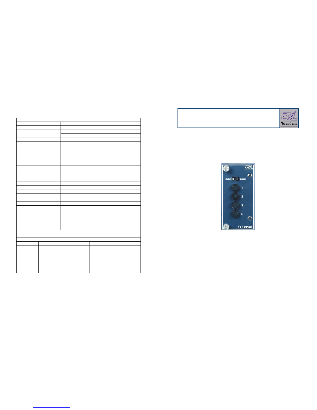
Remote control unit
Features
The 5S2694 video remote control panel can be connected via the 9 way D-type
socket on the 5SV2693 rear connector unit. Whilst the remote control unit is
effectively a de-mountable front panel from a master module, it is supplied with
a metal case for fixing it to the 5S2695 rack mounting strip (which takes up to 4
panels) for EMC compliance.
• Compact 4x1 routing switcher which can be mixed with all other 2600
series modules in standard 1RU or 2RU mounting frames.
• Units can be combined and configured for YUV, YC and RGB or RGBS
switching.
• Front panel and / or remote control.
If supplied with the 5S2696 married/remote cable, up to 3 routing switchers can
be cascaded and a 9-way D type socket is supplied to connect a cable for remote
panel(s).
• On board independent power supply.
• Serial control interface within system levels and remote control panels.
The 9-way D-type connections are as follows:
Installation
Control on 9-way D-type connector
D type pin Use
1 Tx
6 Tx
2 Rx
7 Rx
3 Gnd
8 Gnd
4 VI
9 +5V
5 +5V
Systems are generally delivered with modules (including sub-modules) and
associated rear connector units already installed and configured within frames to
your requirements.
Before installing or re-arranging modules and rear
connector units in 2600 series frames the 2600 range
and frames user guide should be consulted. Section 1.3
‘Safety and pre-installation checks’ includes
instructions that must be followed. Section 2 describes
how to install or re-arrange modules and rear connector
units in 2600 series frames.
Operation
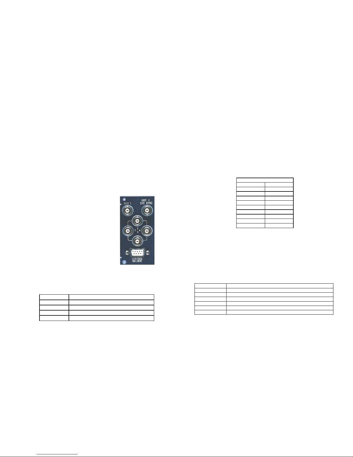
Rear connector units
With the sliding switch in position I (enable), a source can be selected by
pressing the appropriate button (in which the lamp will light to confirm the
cross-point has been selected).
With pre-configured systems input and outputs
connections only need to be made before the system is
operational. The 5SV2692M and 5SV2692S each use a
5SV2693 rear connector unit. Rear connector units are
fitted with BNCs. Inputs and Outputs connections are
shown clearly on the rear connector units.
With the sliding switch in position O (disable) the panel only shows tallies.
When operated with local and remote panels the matrix operates on a last takes
precedence basis. However the sliding switch may be used to disable selection
by one of the panels (but tallies will still be shown).
Front module
Ordering information
The 5SV2692M module is fitted with the front control panel and DIP switches
configured for a master unit (refer to table 3). The 5SV2692S module is fitted
with a blank front panel and DIP switches configured for a slave unit.
5SV2692M Master 4x1 video switcher module including front panel control
5SV2692S Slave 4x1 video switcher module
5S2693 4x1 video rear connector
5S2694 4x1 video remote control panel
9MW26901 Slave switcher front panel
5S2696 Married/remote cable for up to 3 modules
5S2695 19" rack mounting panel for up to 4 remote 5S2694 control panels
Switch Function
1 Always ON
2 Always ON
3 OFF= Master ON= Slave
4 OFF= N/A ON= Video
Table 3
NB Any links fitted should not be changed.
- 2 - - 3 -
 Loading...