

DTL Broadcast 2600 series, 5AV2628, 5AV2628L, 5AV2647 User Manual
Specification
DTL 2600 range
- 4 -
Input
Impedance
75Ω bridging
Return loss <-46 dB to 15 kHz and <-40 dB to 5.5 MHz
Allowable dc superimposed 3 V maximum
Common mode signal level 4 V maximum
CMRR <-60 dB to 15 kHz, <-35 dB to 5.5 MHz
Output
Number
Six 75Ω
Return loss <-40dB (50Hz-5.5MHz)
Isolation <-46dB
dc superimposed
<±20 mV adjustable
Signal level 1 V p-p
Electrical length 18 ns
Consistency Typically 0.5 ns
Video performance
User Guide
Gain control range
±3dB
Frequency response
±0.1 dB to 8 MHz roll off 3 dB/octave
Pulse to bar ratio <0.2% K
Bar slope <0.2% K
Pulse slope <0.2% K
Y/C gain inequality <0.5%
Y/C gain delay
±1 ns
Differential gain <0.2% (12.5%-87.5% APL)
Differential phase
<0. 2° (12.5%-87.5% APL)
Noise added at output
Luminance CCIR weighted <-82 dB
Chrominance CCIR weighted <-75 dB
LF random unweighted <-70 dB
Equalisation
Front panel controls Low, medium and high frequencies
Range
±200m PSF1/3 or equivalent (+0-400m jumper selectable
internally)
Power
Power supply required 230VAC 50Hz
Power consumption 10 VA
Operating temperature
0-40° C
NB Above measurements refer to the 5AV2628 CEDA and associated 5AV2647 rear
connector unit in a 5AV2645 frame using PSF1/3 cable and with all unused outputs
terminated.
Physical
Weight (kg) Height (mm) Width (mm) Depth (mm)
5AV2628 1.000 88 44 300
5AV2628L 1.000 88 44 300
5AV2647 0.210 88 44 120
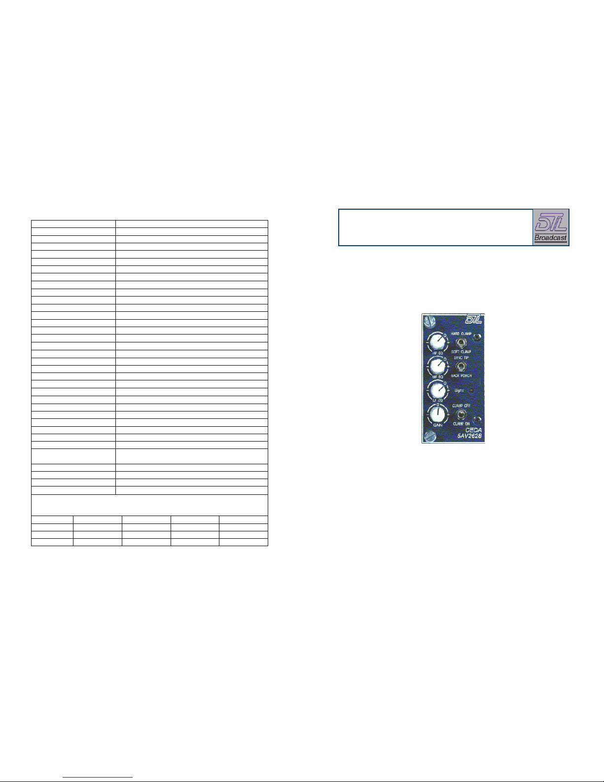
5AV2628 clamped equalising video DA
A precision clamped equalising analogue video distribution
amplifier that, with its associated rear connector unit, provides
six outputs and a differential looping input.
www.dtl-broadcast.com
DTL Broadcast Ltd, Johnson’s Estate, Silverdale Road, Hayes, Middlesex, UB3 3BA, UK
Phone: +44 (0) 20 8813 5200 Fax: +44 (0) 20 8813 5022
Internet: www.dtl-broadcast.com support@dtl-broadcast.com
F:\PRODUCTS\2600\User Guides\UG5AV2628 Iss1.0.doc
Features
- 3 -
input is terminated in 75Ω either on the unit or at the end of any interconnecting
cable. Ensure that all unused outputs are terminated in 75Ω.
The 5AV2628 clamped equalising video distribution amplifier (CEDA) is
designed primarily to equalise signals from outside the studio environment such
as from satellite and microwave links but can also be used to equalise signals
passed through a variety of cable types. Standard (5AV2628) and long timeconstant (5AV2628L) CEDA’s are available, the long time-constant version
providing more compensation at lower frequencies when this is required. The
units are based on the proven 5AV2646 video distribution amplifier and use the
same mating rear connector unit (5AV2647) for input and output connections. .
Front module
The CEDA fits into the frame from the front and is secured by two
thumbscrews. This may be done with the frame powered.
The signal LED when lit, shows that the unit is receiving mains and the internal
power supply is functioning & turns from red to green when an input video
signal is present.
Video input screen can be floating or grounded depending on the user’s
requirements. CEDA's are shipped with the screen floating so that input
common mode signals are rejected. It may be necessary to ground the input
screen, for instance in cases where lightning induction is a problem. To ground
the input screen link LK1, found near the edge connector pins on the component
side on the VDA motherboard.
• +ve and ve wide ranging equalisation to compensate for under and over
equalised signals. Equalises for >200m PSF1/3 or equivalent (+0-400m
jumper selectable internally).
• Inherently high CMRR that effectively eliminates common mode hum
pick up on lines.
• The signal LED turns from green to red when there is no input video
present
Front panel gain and equalisation controls are at
unity gain and 0m equalisation when the knob
pointers align with the panel marker. Turning
the control clockwise increases, and
anticlockwise decreases, the Gain and
Equalisation respectively. Section 3.1 describes
the alignment procedure using a Pulse & Bar test signal to equalise a signal.
• Front panel adjustments for gain and low, medium and high equalisation
frequencies.
• A clamp circuit with switched options on the front panel. Designed to
considerably reduce the effect of differential mode hum or jitter on the
input signal it can be switched on or off.
• Hard or soft clamping is selectable on the front panel to eliminate
excessive or slight differential hum or jitter.
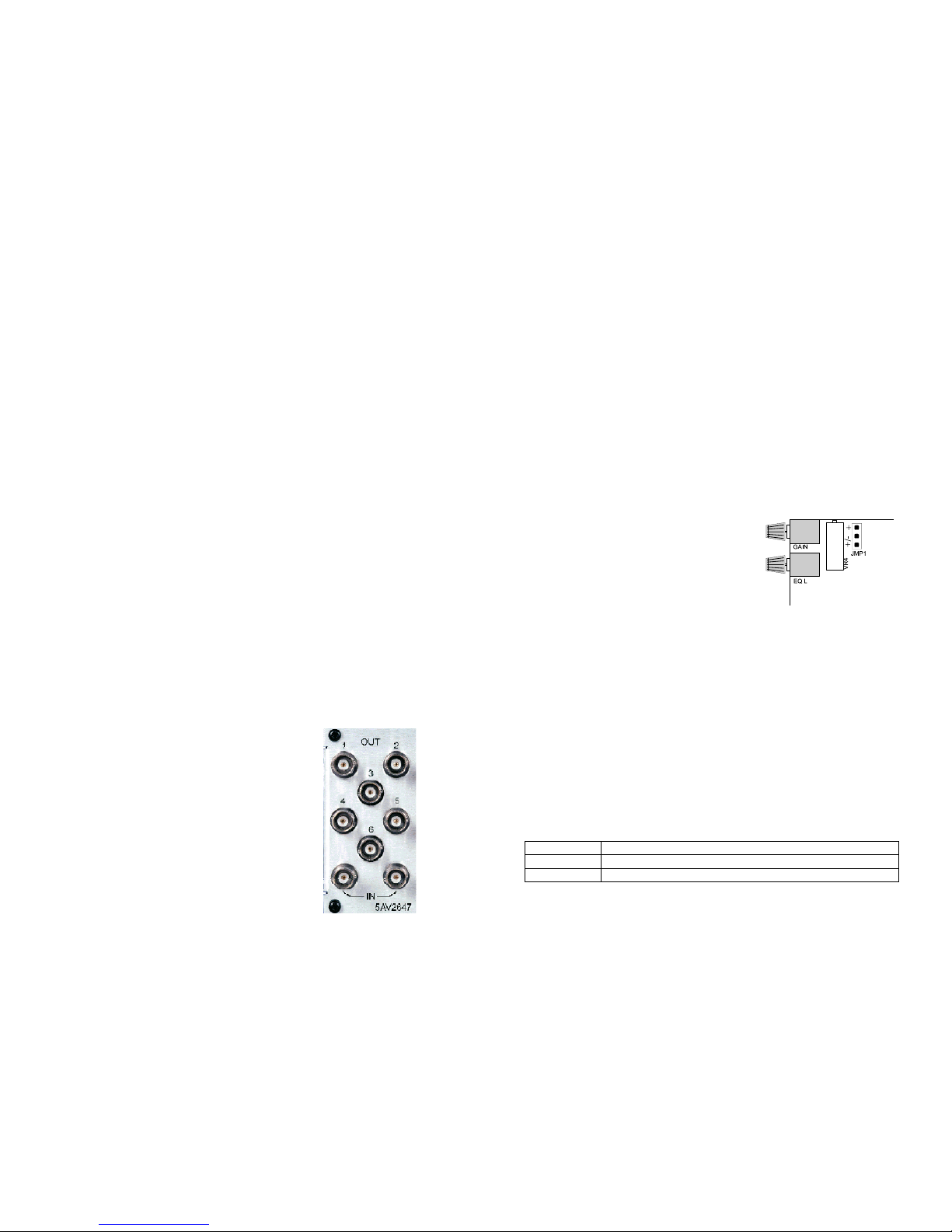
The +ve equalisation range can be greatly increased at the expense of ve
equalisation, by moving the jumper to + on JMP1 on the sub-board. Access to
the link is by sliding the module half way out of the frame and its location is as
shown in the sketch. CEDA’s leave the factory with JMP1 set to +/.
• Back-porch or sync-tip clamping allows the user to choose the most
effective clamping point for the input signal.
• Passes sound in sync.
Clamping is done by feedback in which the output is sampled, an error signal
derived by comparing the sample to a reference, and then the output drift
corrected by adding back the inverse of the error with a selectable timeconstant. One switch on the front panel allows the clamp to be switched on or
off, another allows the clamp time-constant to be selected between hard (short)
and soft (long) while a third allows the point at which the clamp operates to be
selected between back-porch or sync-tip. Hard time-constant will be selected
when excessive differential signal components have to be removed, though a
soft time-constant is recommended for normal operation. Sync-tip or backporch clamping will be selected by the user for the portion that is least noisy.
Installation
Systems are generally delivered with modules
(including sub-modules) and associated rear connector
units already installed and configured within frames to
your requirements.
Before installing or re-arranging modules and rear
connector units in 2600 series frames the 2600 range
and frames user guide should be consulted. Section 1.3
‘Safety and pre-installation checks’ includes
instructions that must be followed. Section 2 describes
how to install or re-arrange modules and rear connector
units in 2600 series frames.
Ordering information
5AV2628 Clamped equalising video distribution amplifier (CEDA)
5AV2628L Long time-constant CEDA
5AV2647 Connector unit with looped through input and 6 output
Rear connector units
- 2 -
Input and output BNC connections are clearly shown
on the rear connector unit. Ensure that the looping
 Loading...