

Page 1
HV-500 TECHNICAL
DESCRIPTION
B ETA VE R S I ON
www.drivetraininnovation.com
V1.31
Page 2

HV-500 TECHNICAL DESCRIPTION (BETA VERSION)
2
Revision 1.31
CONTENTS
Overview ......................................................................................................................................................... 3
History ......................................................................................................................................................... 3
Related documents ..................................................................................................................................... 3
Liability and safe use of this unit ..................................................................................................................... 4
Main features .................................................................................................................................................. 5
Specifications................................................................................................................................................... 5
Current limit reduction .................................................................................................................................... 6
Power loss ....................................................................................................................................................... 6
Efficiency ......................................................................................................................................................... 7
physical description ......................................................................................................................................... 8
Mounting options ........................................................................................................................................ 9
Connections ................................................................................................................................................... 10
Harness connector pinout (H) ................................................................................................................... 10
Motor sensor connector pinout (M) ......................................................................................................... 11
Incremental encoder + SSI ..................................................................................................................... 11
Hall sensors ........................................................................................................................................... 12
High power connection ............................................................................................................................. 12
Liquid cooling connection ......................................................................................................................... 12
PC connection and control ............................................................................................................................ 13
Wiring ............................................................................................................................................................ 13
Harness connector wiring.......................................................................................................................... 14
Input supply ........................................................................................................................................... 15
Analog input .......................................................................................................................................... 15
Digital input ........................................................................................................................................... 15
Digital output......................................................................................................................................... 15
CAN periphery ....................................................................................................................................... 15
RS 232 pheriphery ................................................................................................................................. 16
Motor sensor connector wiring ................................................................................................................. 16
Encoder ................................................................................................................................................. 16
Hall sensor ............................................................................................................................................. 17
High voltage wiring .................................................................................................................................... 18
Page 3
HV-500 TECHNICAL DESCRIPTION (BETA VERSION)
3
Revision 1.31
OVERVIEW
Read the manual carefully and thoroughly before using the controller. If you have
any questions, please contact us. [email protected]
History
07/2016
IGBT and IGBTdriver testing
09/2016
Seventh version final box design
05/2017
Second version prototype hardware testing
11/2017
Using and testing the FOC algorithm for the third version prototype hardware
12/2017
Testing in an automotive environment
02/2018
Final construction
04/2018
Testing in an aerospace environment
05/2018
Adding the resolver and Sin/Cos encoder
07/2018
V1.0 User manual basic specifications
09/2018
Field oriented control with hall sensor improvement
01/2019
V1.1 User interface. Digital I/O and low power wiring diagrams added
Developing field weakening.
03/2019
V1.2 Adding efficiency measurement grap
04/2019
V1.3 High voltage wiring description
Related documents
• DTI Tool user manual
• Motor calibration description
• Analog input setup description
• Can communication description
• Wiring example
Page 4

HV-500 TECHNICAL DESCRIPTION (BETA VERSION)
4
Revision 1.31
_________________________________________________
LIABILITY AND SAFE USE OF THIS UNIT
DTI Controller hardware, DTI Tool and the DTI firmware are experimental products designed to develop
and test electrical systems incorporating electric motors or actuators. Electrical systems can cause danger
to humans, property and nature; therefore precautions shall be taken to avoid any risk. Under no
circumstances shall the device be used where humans or property are put to risk without thoroughly
validating and testing the whole system. Software and hardware interact in various ways, and developers
cannot foresee all possible combinations of hardware used together with software, nor problems that can
occur in these different combinations. Tool and the DTI firmware are experimental software designed to
develop and test. Electrical systems can cause danger to humans, property and nature; therefore
precautions shall be taken to avoid any risk.
Things that can happen, even when using the correct settings, are
• electrical failure
• fire
• electric shock
• hazardous smoke
• overheating motors and actuators
• overstrained power sources, causing fire or explosions (e.g.
Lithium Ion Batteries)
• motors or actuators stopping from spinning/moving
• motors or actuators locking in, acting like a brake (full stop)
• motors or actuators losing control over torque production (uncontrolled acceleration or braking)
• interferences with other systems
• other non-intended or unforeseeable behavior of the system
DTI Tool and the DTI firmware are developer tools that for safety reasons may only be used
• by experts and experienced users, knowing exactly what they do.
• following safety standards applicable in the area of usage.
• under safe conditions where software or hardware malfunction will not lead to death, injuries or
severe property damage.
• keeping in mind that software and hardware failures can happen. We can't give any warranty
because every system is unique and we cannot make sure its safety. Although we design our
products to minimize such issues, you should always operate with the understanding that a
failure can occur at any point of time and without warning. As such, you shall take the
appropriate precautions to minimize danger in case of failure.
DTI does not assume any responsibility for difficulties, which are the result of inappropriate configuration,
electric system structure and settings that are not in accordance with the latest version of the manual for
DTI inverters.
Every inverter is tested before shipping. DTI assumes no liability in case a customer uses components for
the purposes for which they have not been developed or tested.
DTI reserves the right to change any information included this manual. All connection circuitry described
is meant for general information purposes and is not mandatory. DTI does not assume any liability,
expressively or inherently, for the information contained in this manual, for the functioning of the device
or its suitability for any specific application.
Page 5
HV-500 TECHNICAL DESCRIPTION (BETA VERSION)
5
Revision 1.31
MAIN FEATURES
• Sensored FOC motor control
• Analog and digital inputs for control
• CAN (ISO 11898-2), UART communication
• Duty-cycle, speed or torque control
• Regenerative braking
• Hand brake function
• Motor angle positioning
• Motor sensors: UVW Hall sensors, SSI, resolver or ABI encoder
• Hardware and Software overcurrent and overvoltage protection
• Undervoltage limitation and protection
• IGBT and motor overtemperature protection
• Encoder wire damage protection
• Maximum motor speed limitation
• Maximum power limitation
• DC and AC current limitation
• Different setup for reverse operation
• Adjustable non-linear or linear analog input caracteristics
• Adjustable reverse switch or centerized analog input for reverse operation
• Simplified motor setup for perfect current control
Awaiting completion…
SPECIFICATIONS
Maximum operating voltage:
700 V
Continuous/peak AC current:
400 A / 500 A depending on the temperature
Maximum power dissipation:
6000 W
Maximum electric RPM:
100.000 (10.000 physical RPM with 10 pole pair motor)
Maximum operating temperature:
100°C
Switching frequency:
8-14 Khz
Dimension (h/w/l):
77/213/420mm
Weight:
6,7 kg
Integrated liquid cooler
IP65 waterproof design
Page 6
HV-500 TECHNICAL DESCRIPTION (BETA VERSION)
6
Revision 1.31
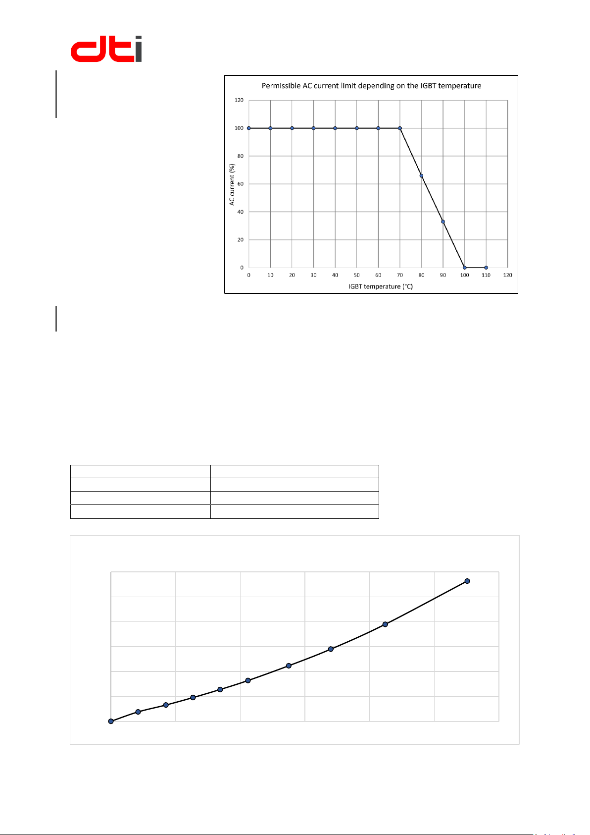
CURRENT LIMIT
REDUCTION
Maximum stepless AC current
limit depending on the IGBT
temperature in order to protect
them from damage.
POWER LOSS
The dissipated power depends on:
• PWM switching frequency
• AC frequency (motor rotation frequency)
• AC current
• AC voltage
• DC voltage
With a calculated example we demonstrate the power loss of the inverter. Power loss can be seen
compared to AC current.
Power loss calculated with the following inputs:
DC voltage:
370 V
Motor KV:
13 [RPM/V]
PWM switching frequency:
10.000 Hz
AC electric frequency:
20.000 Hz (2000 RPM with EMRAX)
0W
500W
1000W
1500W
2000W
2500W
3000W
0A 100A 200A 300A 400A 500A 600A
Total power loss
Page 7
HV-500 TECHNICAL DESCRIPTION (BETA VERSION)
7
Revision 1.31
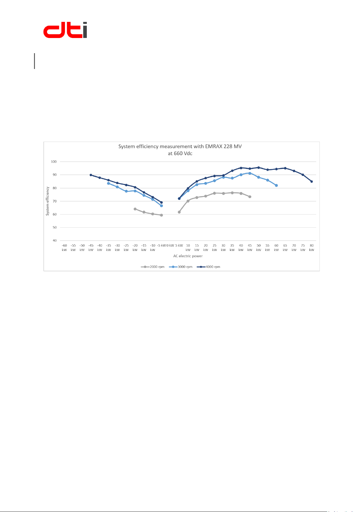
EFFICIENCY
The efficiency of the system is influenced by many factors. In order to achieve good efficiency, the voltage
difference between inverter AC and DC must be taken into account. Lower voltage difference, means
better efficiency. The AC voltage is determined by the motor-generated voltage. This value is directly
proportional to the motor speed.
In addition, the AC current, the switching frequency, and the AC frequency have a significant effect on
efficiency.
We used an medium voltage EMRAX 228 motor with high 660 Vdc for efficiency measurement.
Page 8
HV-500 TECHNICAL DESCRIPTION (BETA VERSION)
8
Revision 1.31
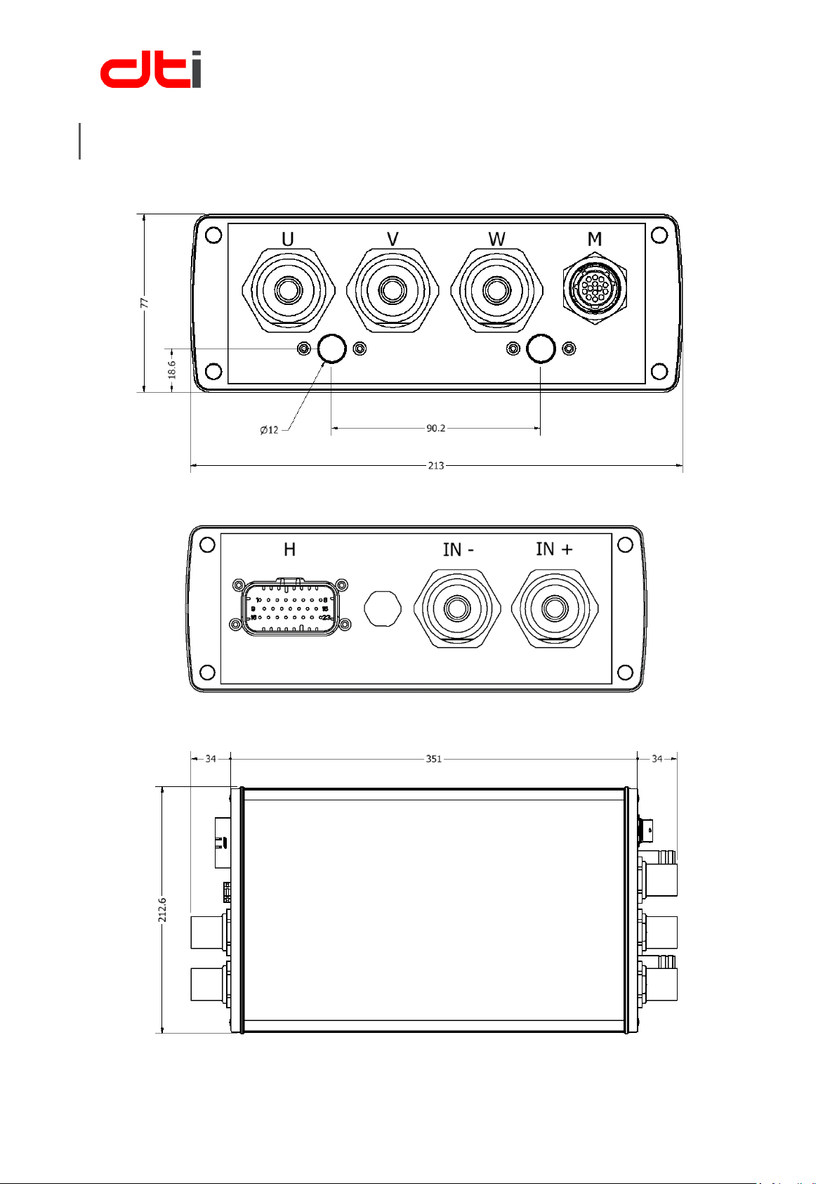
PHYSICAL DESCRIPTION
Dimensions are shown in mm
Page 9
HV-500 TECHNICAL DESCRIPTION (BETA VERSION)
9
Revision 1.31
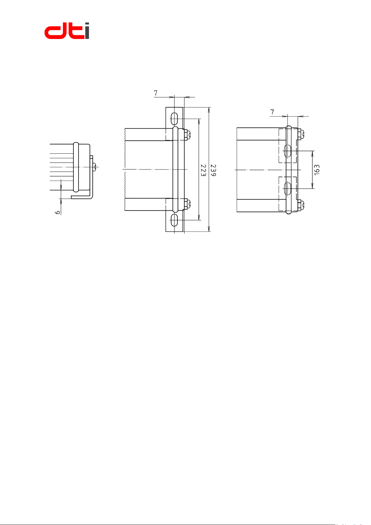
Mounting options
4 X M4 screws
Page 10
HV-500 TECHNICAL DESCRIPTION (BETA VERSION)
10
Revision 1.31
CONNECTIONS
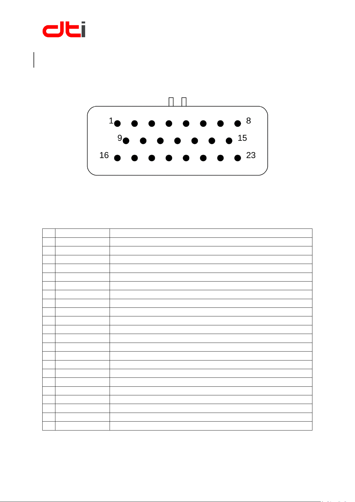
Harness connector pinout (H)
Connector type: TE CONNECTIVITY AMPSEAL 776228-1
Harness side connector type: TE CONNECTIVITY AMPSEAL 770680-1
16-20 AWG crimp pin type: TE CONNECTIVITY AMPSEAL 770520-1
1
12_VIN
Auxiliary voltage plus, 9 V – 15 V maximum 30 W
2
D_OUTPUT_1
Open Drain output, maximum 25 V, 240 mA
3
CAN1_L
CAN Low, 24 V supressor diode
4
CAN2_L
CAN Low, 24 V supressor diode
5
USART_RX
Serial communication, RS232
6
D_INPUT_1
Output power enable, 12 V input, active high
7
+5V_OUT
5 V output for sensors, total maximum 500 mA
8
BRAKE_IN
Analog input, maximum 5 V
9
12_VIN
Auxiliary voltage plus, 10 V-26 V maximum 36 W
10
D_OUTPUT_2
Open Drain output, maximum 25 V, 240 mA
11
CAN1_H
CAN High, 24 V supressor diode
12
CAN2_H
CAN High, 24 V supressor diode
13
USART_TX
Serial communication, RS232
14
D_INPUT_2
Digital input, 12 V input, active high
15
ANALOG_IN
Analog input, maximum 5 V
16
GND
Auxiliary voltage minus
17
GND
Auxiliary voltage minus
18
GND
Auxiliary voltage minus
19
D_OUTPUT_3
Open Drain output, maximum 25 V, 240 mA
20
D_OUTPUT_4
Open Drain output, maximum 25 V, 240 mA
21
+5 V_OUT
5 V output for sensors, total maximum 500 mA
22
+5 V_OUT
5 V output for sensors, total maximum 500 mA
23
+5 V_OUT
5 V output for sensors, total maximum 500 mA
Page 11
HV-500 TECHNICAL DESCRIPTION (BETA VERSION)
11
Revision 1.31
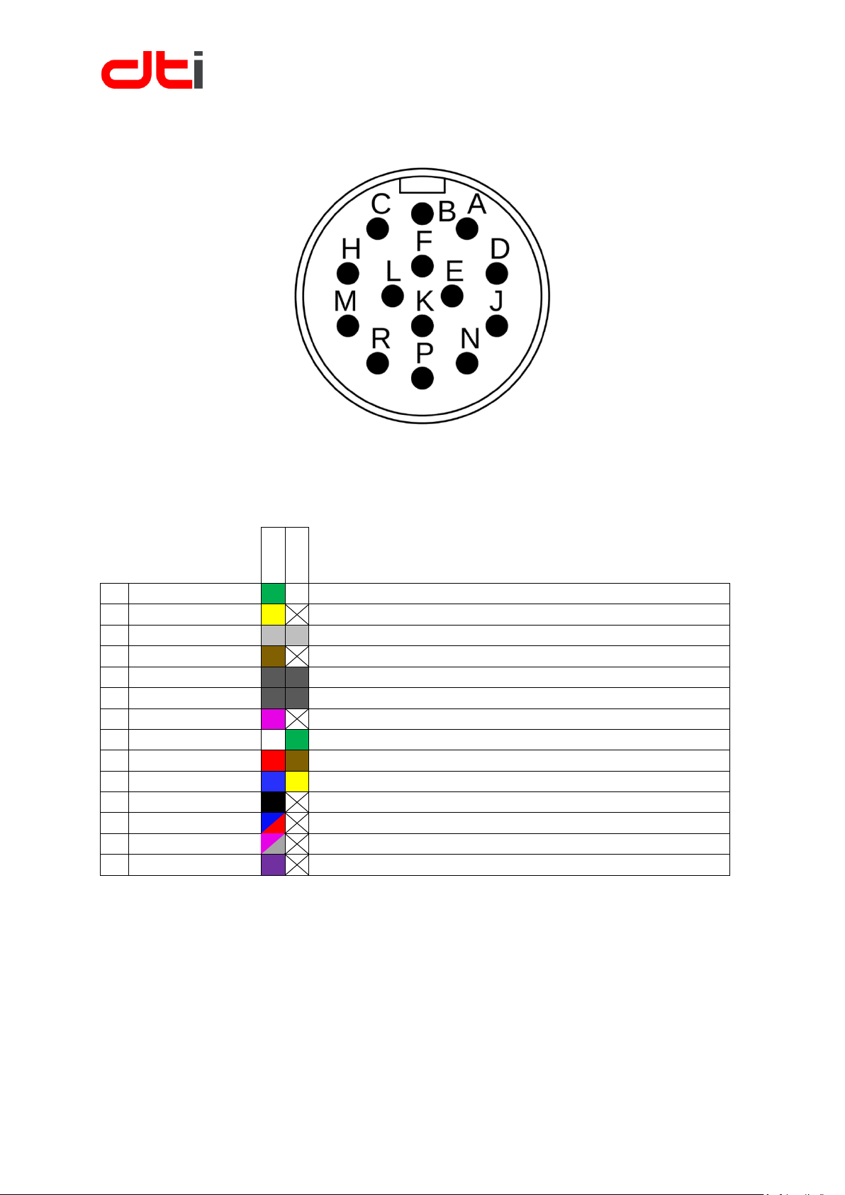
Motor sensor connector pinout (M)
Connector type: SOURIAU UTS712D14S32
Harness side connector type: SOURIAU UTS6JC12E14P
R
M
4
4
H
A
L
L
A
B+ / Hall U
ABI encoder „B” differential signal positive or A hall sensor
B
B-
ABI encoder „B” differential signal negative
C
A+ / Hall V
ABI encoder „A” differential signal positive or B hall sensor
D
Z-
ABI encoder „Z” differential signal negative
E
TEMP
Temperature sensor
F
GND
Temperature sensor ground
H
A- /
ABI encoder „A” differential signal negative
J
Z+ / Hall W
ABI encoder „Z” differential signal positive or C hall sensor
K
+5 V
Encoder or hall sensor supply output
L
GND
Encoder or hall sensor ground
M
CLK+
ABI encoder SSI „CLK” differential signal positive
N
DATA-
ABI encoder SSI „DATA” differential signal negative
P
DATA+
ABI encoder SSI „DATA” differential signal positive
R
CLK-
ABI encoder SSI „CLK” differential signal negative
Sensor connection diagram
INCREMENTAL ENCODER + SSI
• Compatible with normal or differential signals.
• ±15 kV ESD-Protected signals
• Maximum input signal voltage: 5 V
• Maximum encoder resolution: 4096 (counts per revolution)
• Maximum input frequency: 400 Khz
Usable encoders: RLS RM44SI,
Page 12
HV-500 TECHNICAL DESCRIPTION (BETA VERSION)
12
Revision 1.31
HALL SENSORS
• Latching type Hall-effect sensors input
• Maximum input signal voltage: 5 V
• Maximum input frequency: 400 Khz
High power connection
CP-600 type custom made connector. 600 A peak load capacity.
Female connector tightening torque: 5 Nm
Maximum wire size: diameter 10 mm or 2/0 AWG or 50mm2
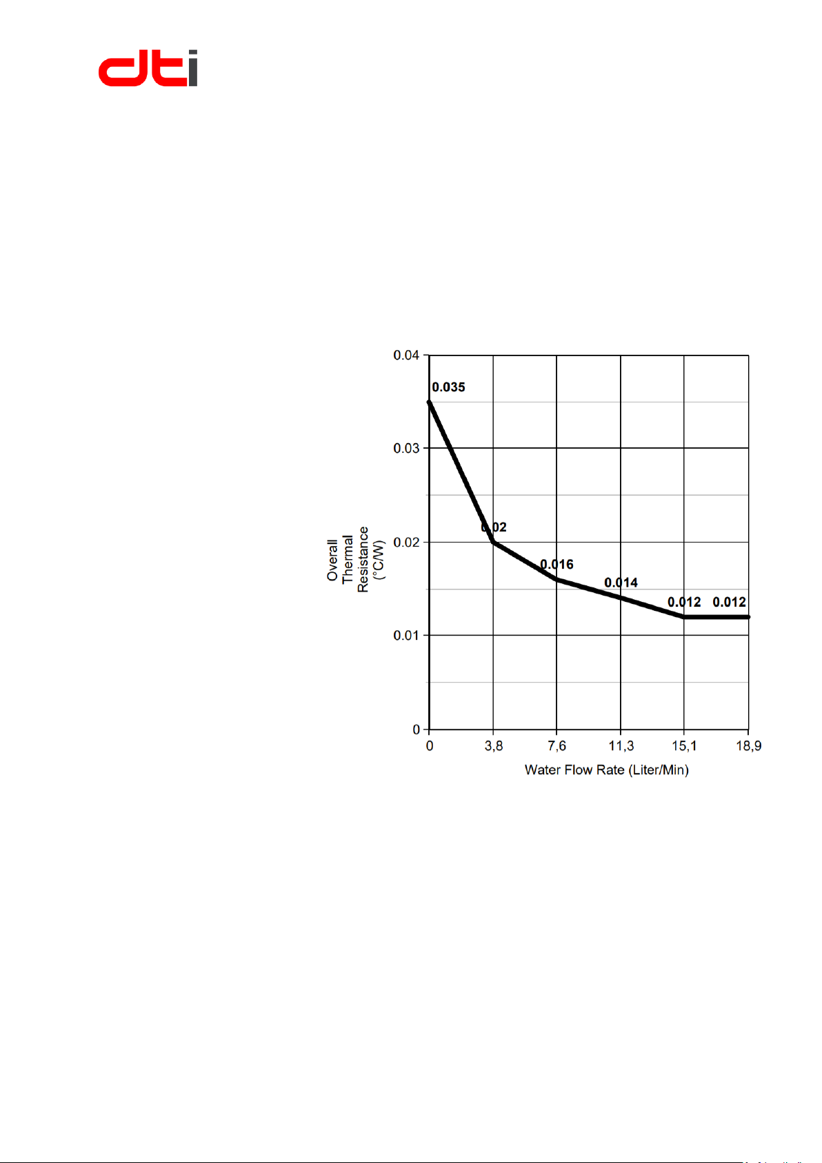
Liquid cooling
connection
Liquid tube connection outer
diameter: 12 mm
Pipe material: copper
Maximum pressure: 4 bar
(15,1 Liter/Min = 0,9 bar)
Page 13

HV-500 TECHNICAL DESCRIPTION (BETA VERSION)
13
Revision 1.31
PC CONNECTION AND CONTROL
You can connect the inverter with a USB to RS-232 adapter (for example: ATEN UC232A) to the PC, where
the inverter can be parameterized. Use the „H” connector 5. and 13. pins and ground to common
potential. The DTI Tool software can be run on the PC.
The DTI Tool compatible with windows 10 x86 or x64.
If you would like to use another operating system, please contact us [email protected]
DTI Tool features:
• Real time data analysis
• Online data logging just with DTI Tool
• Error checking and logging
• Motor position sensor setup, inspection
• Online motor control with keypad (very carefully)
• Setting input parameters
• Very detailed query of measured current and voltage (like oscilloscope)
WIRING
Analog and digital signal inputs and outputs are provided for switches, sensors, contactors, hydraulic
valves, CAN communications, RS232 communications and SSI communications.
The wiring must be carried out by a qualified person.
It must be paid attention to the equipotential bonding for components which are connected to the unit
and which do not have isolated inputs and outputs (equalizing connection GND). The equalizing currents
may destroy components and parts.
The units, the inductive and capacitive accessories as well as the power wiring can generate strong
electric and electromagnetic fields. These fields may be dangerous for persons having electronic medical
aids or appliances (e.g. cardiac pacemakers). Sufficient distance to these electrical parts must be
observed. The switch cabinet must be labeled accordingly.
Keep all wiring harnesses short and route wiring close to vehicle metalwork. Keep all signal wires clear of
power cables and consider the use of screened cable. Keep control wiring clear of power cables when it
carries analogue information - for example, accelerator wiring. Tie all wiring securely.
Do not apply power until you are certain the controller high power and signal wiring is correct and
has been double checked. Wiring faults will damage the controller.
Page 14
HV-500 TECHNICAL DESCRIPTION (BETA VERSION)
14
Revision 1.31
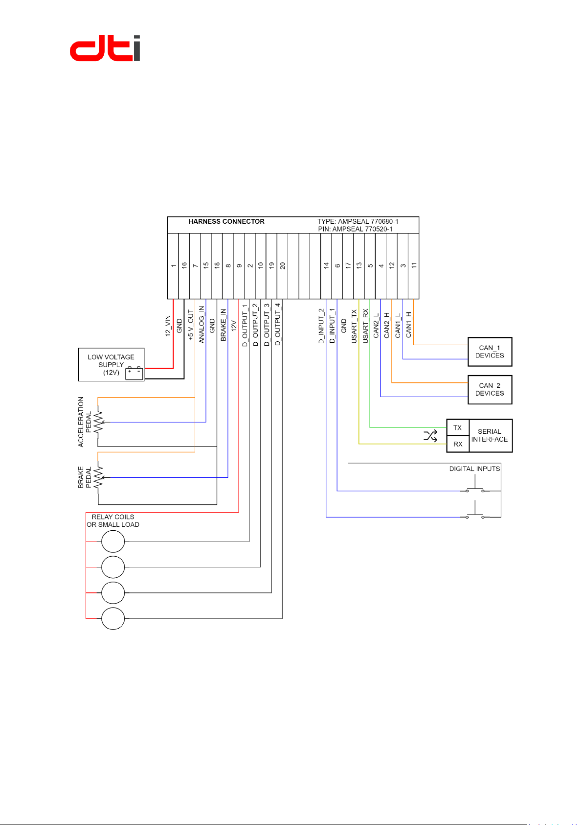
Harness connector wiring
You must use a TE CONNECTIVITY connector parts. The harness side connector type: 770680-1 and the
corresponding crimp pins: 770520-1 for 16-20 AWG wire
A special hand crimp tool is required for crimping the pins: 58529-1
Try to create the simplest and shortest wiring harness as possible. You can involve the harness with cable
sleeving polyamide or polypropylene spiral, you can protect it from external influences
Harness connector wiring diagram
Page 15
HV-500 TECHNICAL DESCRIPTION (BETA VERSION)
15
Revision 1.31
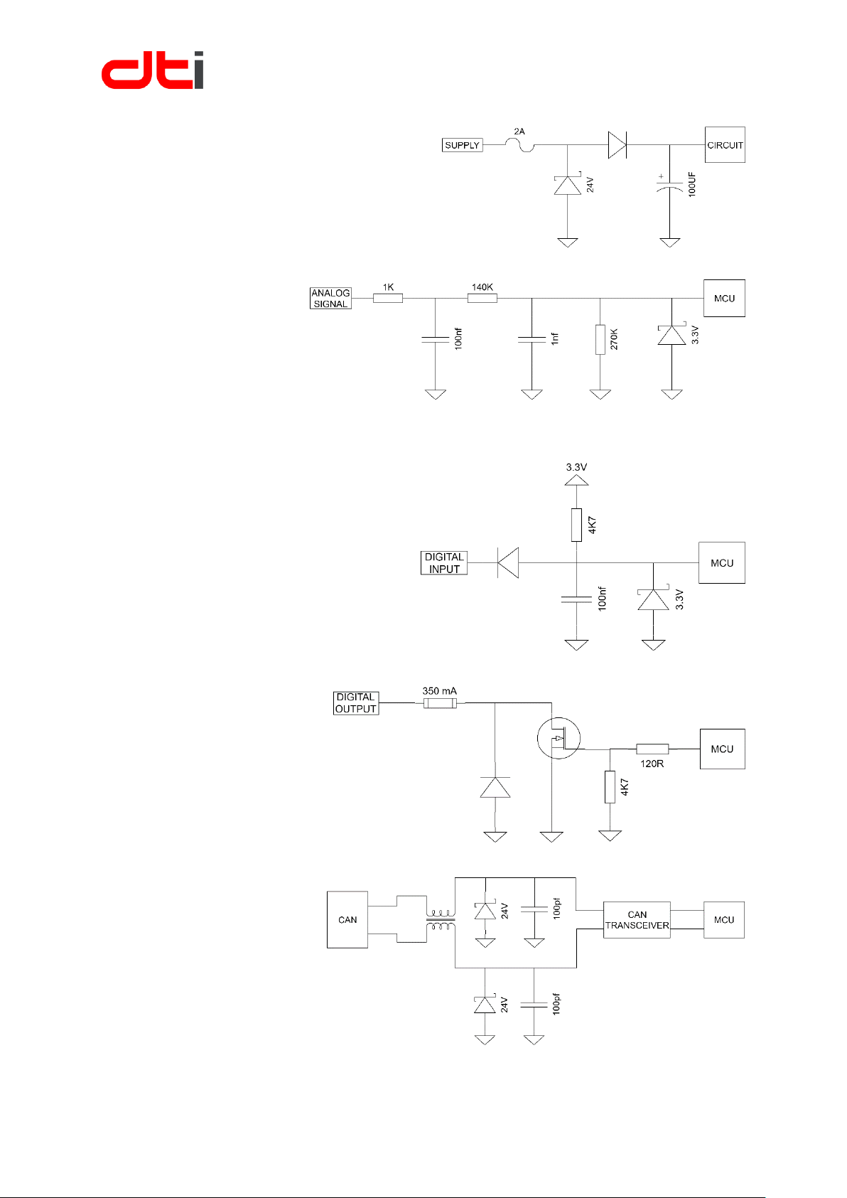
INPUT SUPPLY
▪ Reverse polarity protection
▪ Overvoltage protection
▪ Resettable overcurrent protection
▪ Power supply: 9-15V
ANALOG INPUT
▪ High frequency filter
▪ Overvoltage protection
▪ Maximum 5V input
DIGITAL INPUT
▪ Button debounce
▪ Overvoltage protection
▪ Internal pullup resistor
DIGITAL OUTPUT
▪ Maximum 24V
▪ High-Speed resettable fuse
▪ Maximum 240 mA holding
current
▪ Internal freewheeling diode
CAN PERIPHERY
▪ Common mode coil filter
▪ ESD protection
Page 16
HV-500 TECHNICAL DESCRIPTION (BETA VERSION)
16
Revision 1.31
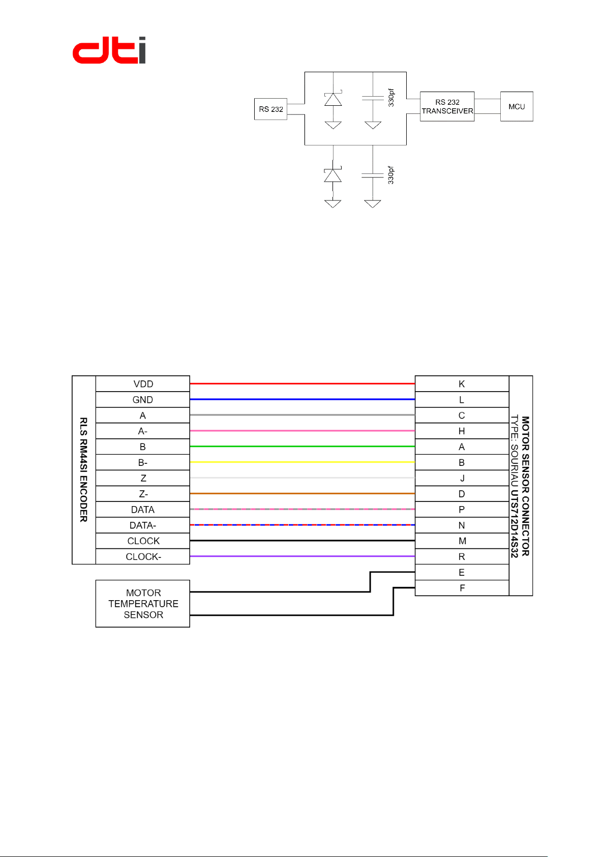
RS 232 PHERIPHERY
▪ ESD protection
▪ Internal serial transceiver
Motor sensor connector wiring
The motor sensor side connector type: Souriau UTS6JC12E14P.
The wires must be soldered to the connector. Use a shrink tube for each wire to prevent a short circuit.
ENCODER
Be careful when using an RLS encoder, connect all the wires with the shielding. If the shielding is not
connected the encoder will send false signals. The internal circuit contains the 120 ohm terminating
resistors.
RLS encoder wiring diagram
Page 17
HV-500 TECHNICAL DESCRIPTION (BETA VERSION)
17
Revision 1.31
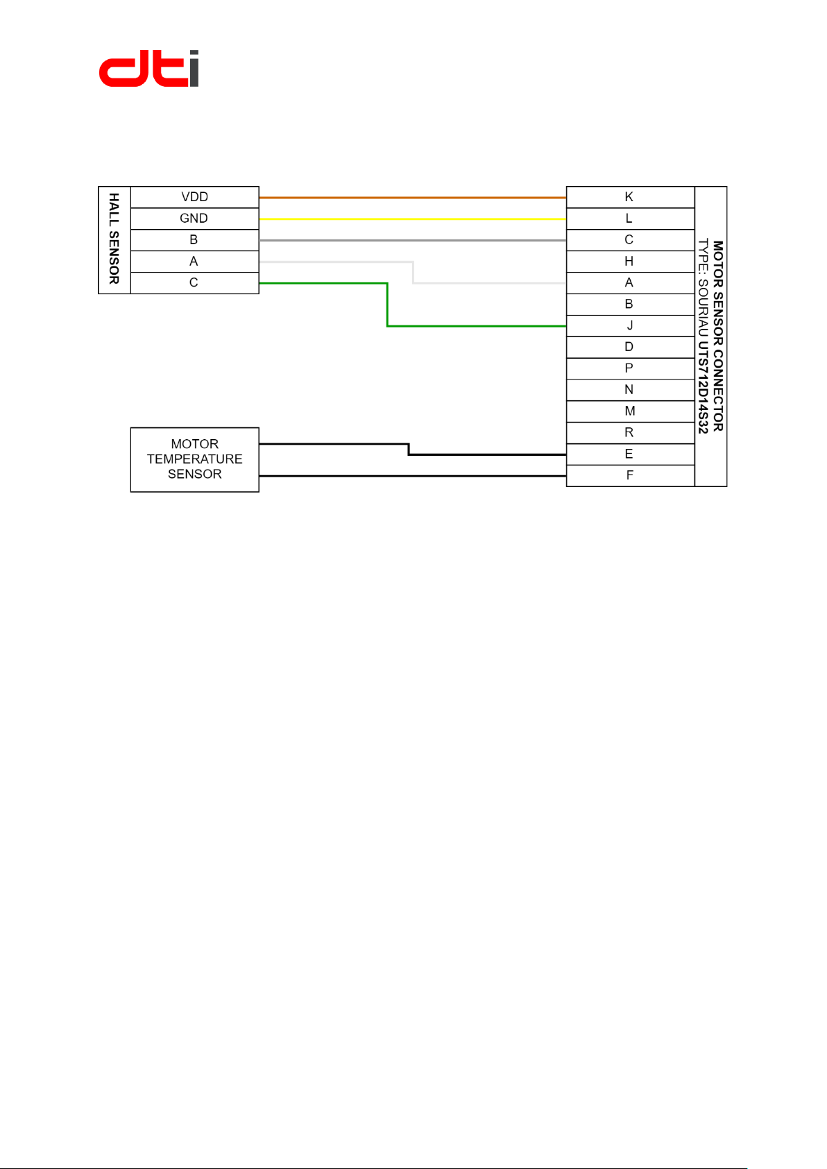
HALL SENSOR
Only connect the wires witch found in the sensor connection diagram. Leave the other pins free on the
connector. The internal circuit contains the hall sensor pull up resistors.
Hall sensor wiring diagram
Page 18
HV-500 TECHNICAL DESCRIPTION (BETA VERSION)
18
Revision 1.31
High voltage wiring
First of all, read "LIABILITY AND SAFE USE OF THIS UNIT". The wiring of the high voltage must be carried
out by a specialist. Keep in mind that DC high voltage is very dangerous and deadly.
Wait for the discharge time before disconnecting the high-voltage connectors. Wait minimum 6 minutes
after switch off the DC voltage.
Use a shielded wire with appropriate shielding points. The AC-side wires must only be connected to the
ground at the motor side. The wires should be as short as possible and as close to each other as possible.
This way the inductance of the wire can be minimized. Please read the CP-600 connector user manual
before use CP-600 connectors
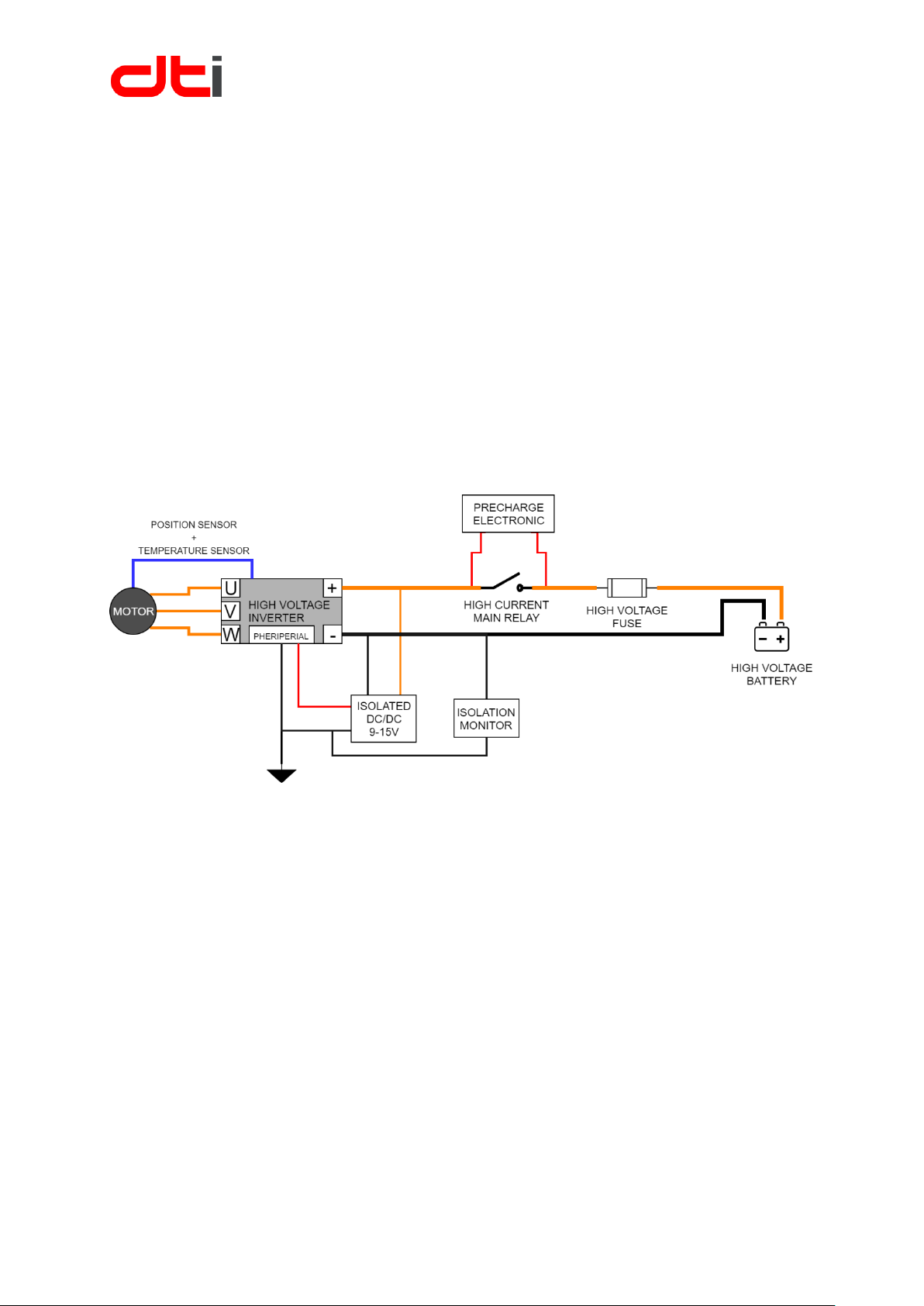
High voltage and low voltage must be electrically isolated. The isolation monitor monitors the isolation
existence. If the monitor detects any error, must turn off the high voltage system.
First install the low voltage part separately and test the peripherals. Use current control mode in the App
Setting/Analog I/O / Analog Input Functions for first testing
The figure illustrates the minimum elements of a high voltage system.
 Loading...