

Page 1
DTI GmbH & Co. KG
Manual
and
Handbook
DTI-Puls
Seite 1 von 31
Page 2

DTI GmbH & Co. KG
DTI-Puls
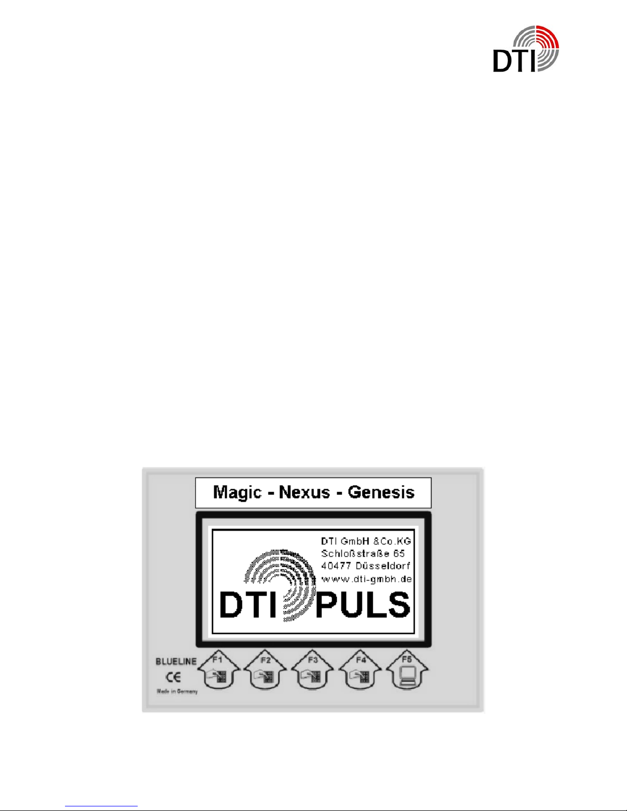
Metal Detectors of the DTI-Puls-Series are working on the basis of Puls-EddySystems. Data handling works completely digital. The system is based on two processors. The first processor is handling the measurement and the calculation of the
datas. The second processor is responsible for management, display, communication
and operating.
Measured data are displayed on a graphic display with 240 x 128 pixel, and via a
built in speaker or headphone. The detector can be driven with several coils. A
menue showing the types of coils is available.
The system works with online metal discrimination. The display shows recognized
objects in different kind of ways.
The software may be adapted according the newest versions. The hardware does
have several plugs für future expandations. The detector can follow technonogical
improvements for a longer time.
The system is prepared for following future expandations:
1. Multi language menues and displays
2. Wireless headphones (already available)
3. Wireless data communication
4. Data recording (Recording of the search on MMC-Card for later analyses on
PC)
5. GPS (Position of searching area)
With a new generation of detectors new problems come up. The user might be erritated by the many possibilities of adjustments.
Only by testing with different objects in the air and in the ground kann help. Changing
parameters will cause different behaviour of the detector.
After a short time you will recognize that handling will not cause problems any more.
Seite 2 von 31
Page 3
DTI GmbH & Co. KG
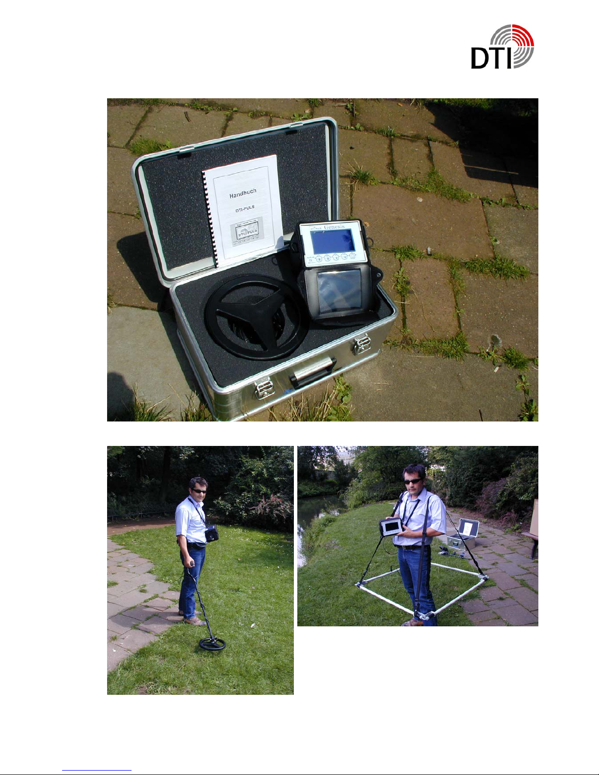
Lieferung in stabiler Alu-Box
Seite 3 von 31
Page 4
DTI GmbH & Co. KG
Assembling
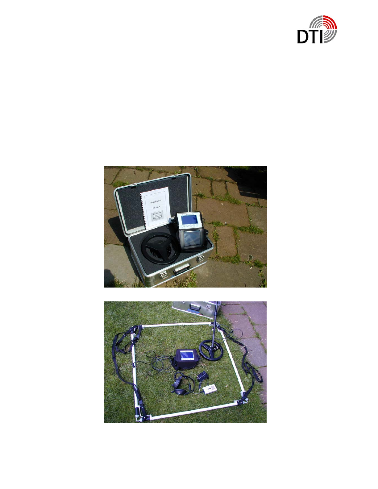
After opening of the Aluminium-Box you will see the electronic unit of the DTI-PulsInstrument, the 28 cm – coil, a manual and a checklist. Take this parts out. Below the coil you
will find the headphone and the battery charger. Furthermore you will see the charging regulator, a cable and rods for the coil.
Mount the coil to the lower rod. Assamble the rods and adjust the length according your body
size. Turn the cable around the rod and put the connector into the female connector of the
electronic unit. Please obey that the connector fits tide.
Seite 4 von 31
Page 5
DTI GmbH & Co. KG
Funktion
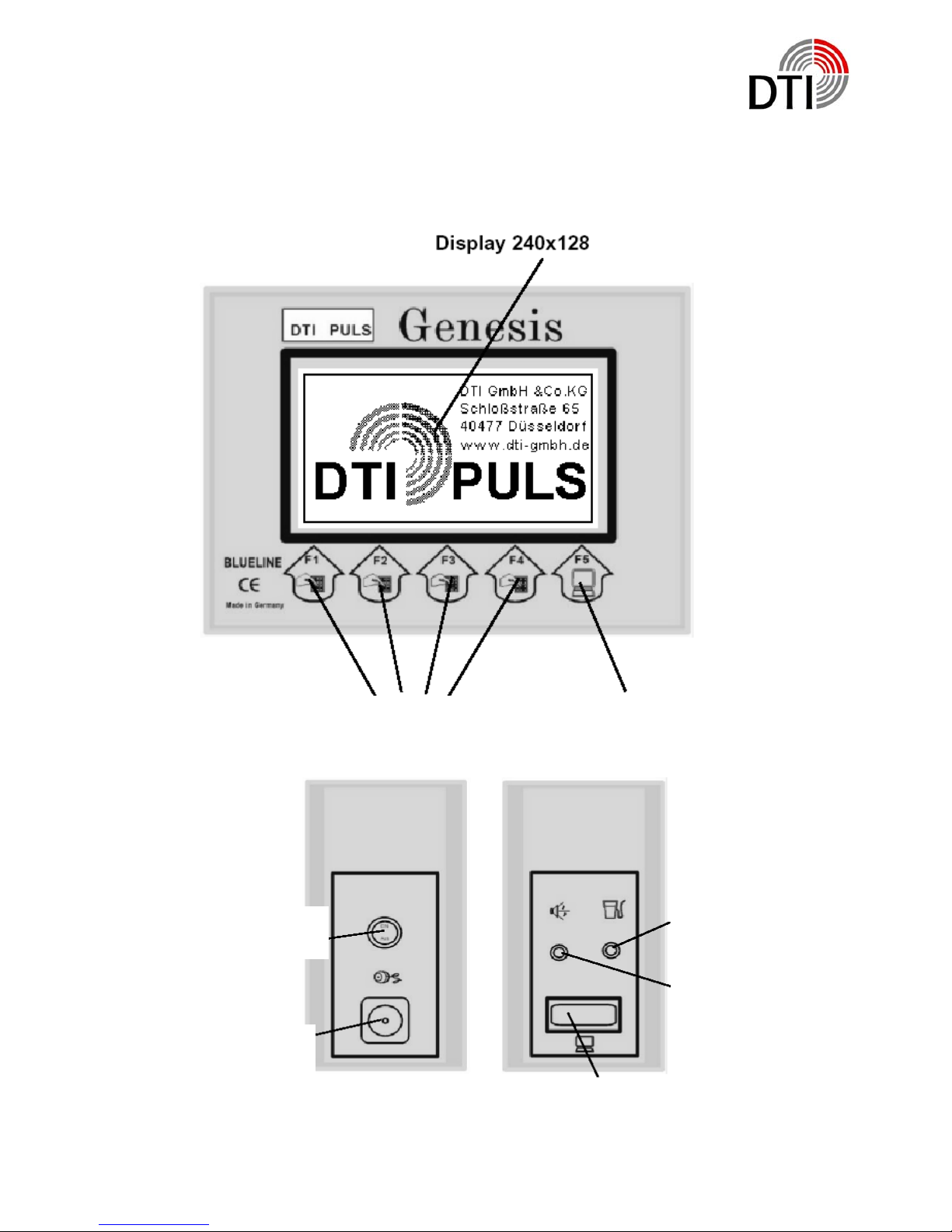
Connecting
Touchkeys F1-F4
Touchkey F5
Back to Graphic Display
Load
On/Off-Switch
Headphone
Connector for
coil
Communication
Connector for PC
Seite 5 von 31
Page 6
DTI GmbH & Co. KG
Five touchkeys allow several functioins. Depending on the menue they have different
functions.
Text The function is shown by a text
Decrese settings - touchkey DOWN
Increse settings - touchhey UP
Back to Menue
Leave Menue
Please obey that a reaction time of up to one second can happen, if you go back to a
menue or if zu leave a menue. After adjustments in the main menue the system always takes a few seconds until it is stable again after leaving the menue.
Please obey that you need to make a REFERENZ after leaving the main menue.
That has to be repleyed when the coil is near the ground.
The detector has a demonstration mode. This mode allows you to become familiar
with the keys and its reactions. The detector has connectors on both sides. Below the
ON/OFF-switch is the coil connector. It has a protecting cap prohibiting coming dirt
and moisture in it. Please put this cap always on if you don’t use the instrument. Always obey to fix the connector tide when you connect the coil. A bad connection
causes uncontrollable currents which can destroi the power amplifier.
On the other side are the load- and the headphone connectors and the communication connector. Headphones with a minimum impedanz of 32 Ohm and 6 mm connector can be used. It should have the possibility to adjust the loudness. The internal
loudspeaker will be switched off when pugging in the connector. The input for the
charger is a 2.1 mm connector. More unter point charging.
The communication connector is a Sub-D9 female connector. This connector will be
necessary for the future software expandation for connecting a personal computer.
Seite 6 von 31
Page 7
DTI GmbH & Co. KG
Setting to Operation
Bevor the first use you should load the detector with the attached charger for 14
hours. Especially when you read a warning after the fist switching on.
If you start directly with the coil please obey the good fitting of the connector. Never
connect a coil when the instrument is switched on. The exeption is when you will be
asked for by the menue. See the chapter Changing Coils.
Look for a place where are not many big metal parts near by. In rooms television or
computers may not be switched on. The emissions of this instruments are being received by the coil.
Switching on:
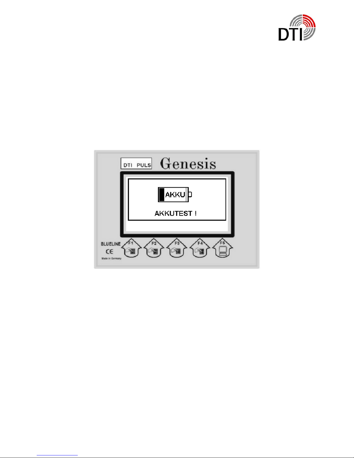
A beep will be produced. The condition of the rechargeable batteries will be checked. If the
rechargeable battery is not ready for operation a message will be displayed. You have to
switch off the detector for charging batteries.
Seite 7 von 31
Page 8
DTI GmbH & Co. KG
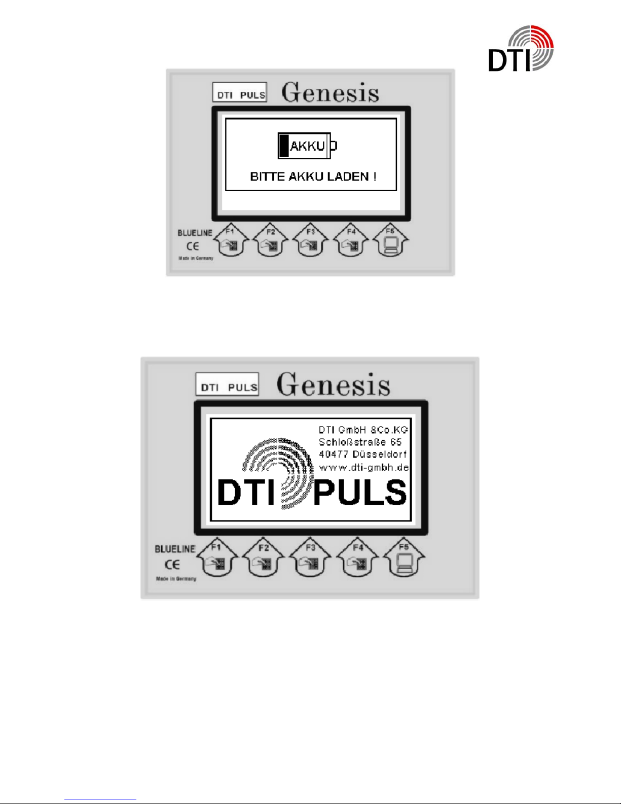
If there is no problem with the rechargeable battery you will see the start logo. Together with the start logo the detector starts sending pulses. The start phases starts.
Seite 8 von 31
Page 9
DTI GmbH & Co. KG
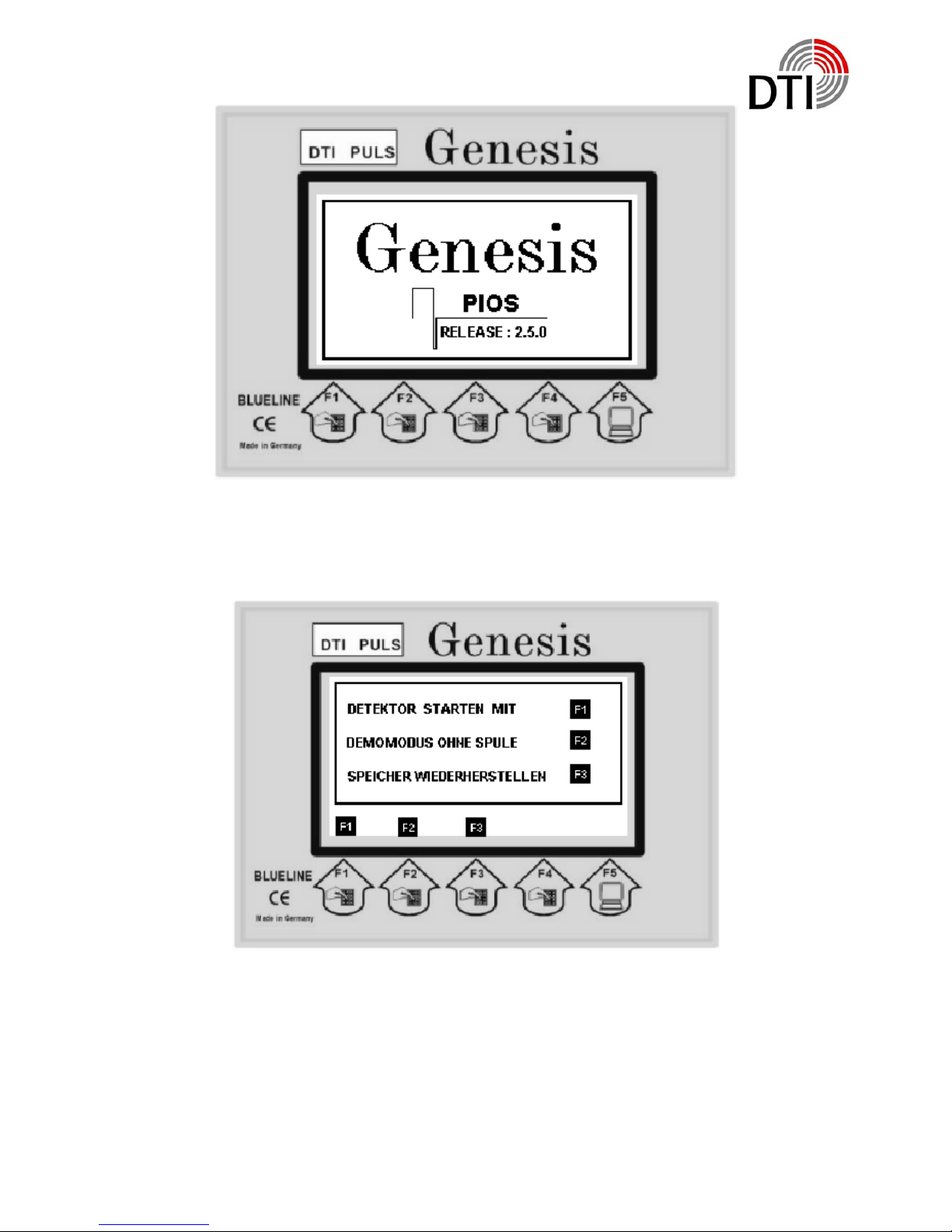
When showing the version number the detector is waiting for ist starting requirements.
You have three possibiities for starting.
F1: Normal start with coil. You press F1.
F2: Start in demonstration mode. No coil is neccessary.
F3: Reset – Set the detector to factory settings.
Seite 9 von 31
Page 10
DTI GmbH & Co. KG
In case of a problem with the communication of both internal processors it can happen that wrong datas are being used. That can happen because of some influence
from outside of by switching on and off in a short time by accident. In this case use
F3 – reset.
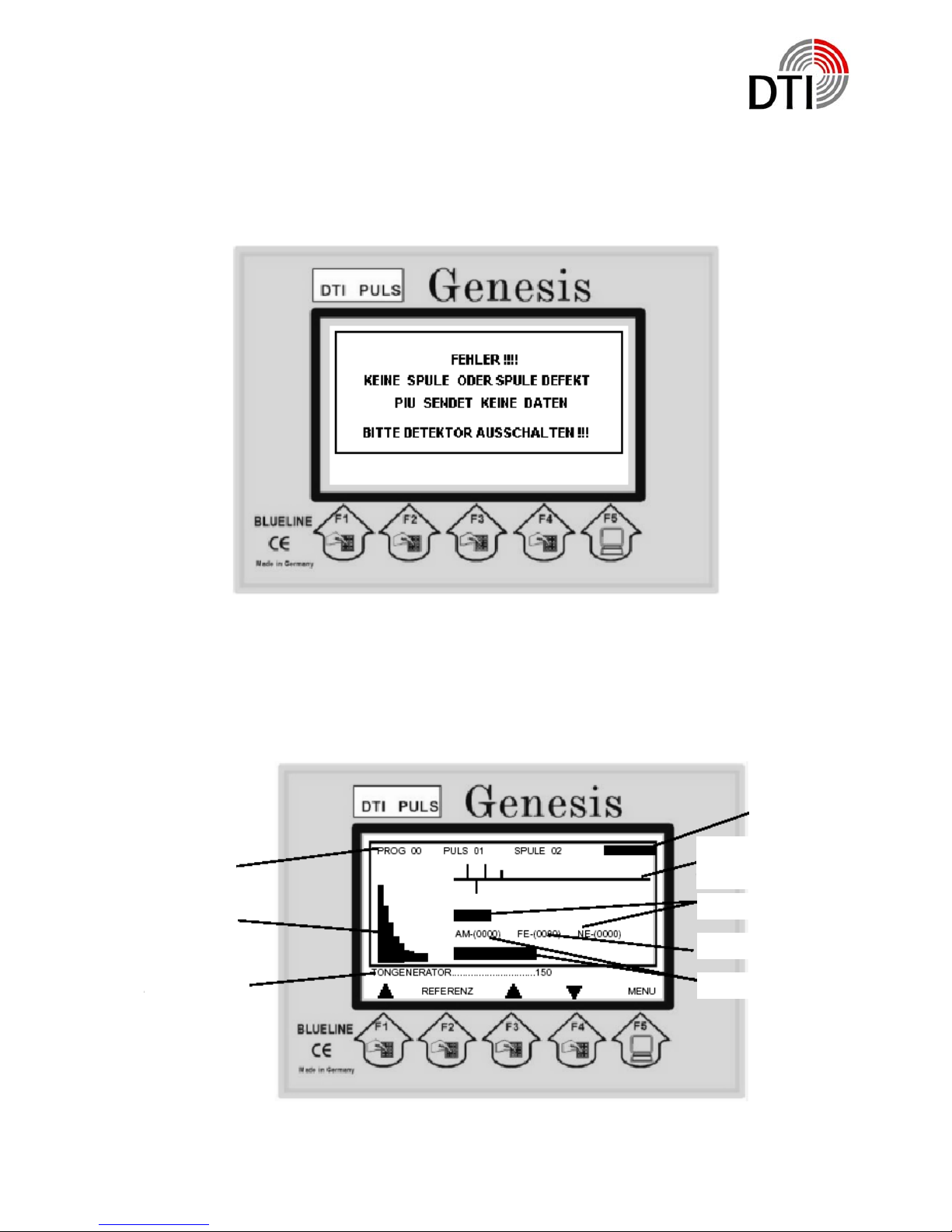
Coil neccessary. System has been startet without coil. Please switch off.
When you choose a start with coil without having connected a coil this message will
be displayed. The system switches to the demonstration mode.
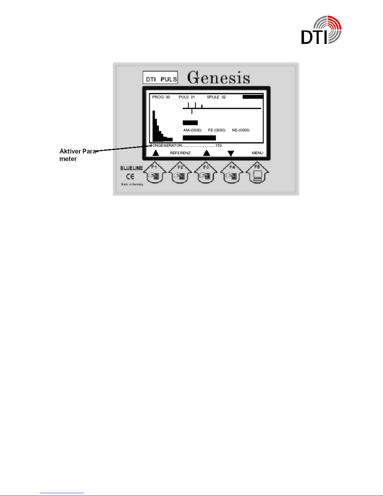
Operation Display
State of
Rechargable
Battery
Record of
measured data
Program
setting
Spectrum
Active
Parameter
The detector now is active and what you are seeing is the operation display.
Seite 10 von 31
Page 11

DTI GmbH & Co. KG
In the start display you are watching the active program (0), the puls power (1) and
the type of coil according to the model (2). In the right the current state of battery capacity. The graphic continuously writes 200 measured data. Above the zero line non
ferrous and below the zero line ferrous metals are being written.
The range of number display is from 0 to 1000 showing the measured signal in live
time. FE is the ferrous and NE the non ferrous metal measured. The non ferrous
metal is been shown in reduced form above the numbers. Below the numbers the
common metal signal is displayed by a bargraph. On the left of the display you will
see the spectrum of measured signal. With help of the spectrum on basis of 9 spectral lines you are able to do an additionally analysis.
Below the ractagle lines there is a line showing parameters which can be changed
online. Also in this line short information are being shown. The last line shows the
actual menue of the pushbuttons. The detector is ready for working immediately, but
it will take 1-2 minutes until coil battery and electronic are termally stable. By pressing
the pushbutton “REFERENZ” the momories are loaded new and set by factory parameters. All driftings will be compensited. If you do a reference above a metal object, this object also will be compensited and can not be detected any more.
Seite 11 von 31
Page 12
DTI GmbH & Co. KG
The detector has the possibility to change parameters online during searching. This
is comparable to the analog function of a potentiometer. So you are able to change
the most important paramters without calling up a menue. Press the pushbutton ‘F3’
e. g. ‘F4’. The number above the key will change accordingly.
After starting always appears
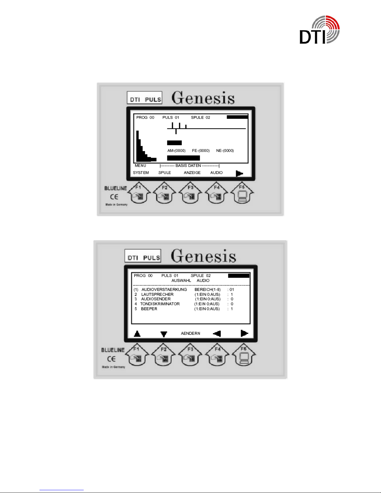
Tongenerator / Tone Generator:
By setting the Tone Generator you adjust the threshold of the tone. You adjust the
strengs of the signal when the first click shall appear. After start always 150 is setted.
The higher you choose the value the smaler the signal strength of a measured object
may be. Generally a click rate of 1-2 will be adjusted without signal.
You press ‚F1’ and as an active parameter you will see
Suchspeicher / Searching Memory:
The main memory of the system has been devided in several layer and sectors. Out
of this memory the searching memory will be generated. There are 1-33 chooseable
searching memories. The detector always starts using the searching memory 11.
This aproves that a detection is possible using all types of coils. The smaler the number of searching memory the more sesitive the detector reacts on smallest objects.
On the other hand that can mean that you will have a permanent detection even in
50 cm hight above the soil and doing a ‘REFERENZ’ will reduce the range of values
dramatically. You have to reference always at the place of using the detector.
Seite 12 von 31
Page 13

DTI GmbH & Co. KG
Depending on the soil concerning the searcing depth it is not possible to give a statement. The settings of the searching memorie will not be stored in memory. So it always has to be set individuelly. The factory setting is a good average value for 28 cm
– 50 cm coils.
You press ‚F1’ and as an active parameter occurs
Audioverstärker / Audio Amplifier:
The audio amplifier multipies the click rate of the tone generater by its value. The
maximum value is 16. If you have a signal with 10 clicks per second the click rate will
be multiplied to 160 when amplifying by maximum. Accordingly the rasing speed of
the audio signal and its sensitivity is rising.
You press ‚f1’ and as an active parameter occurs
Diskriminator / Discriminator:
The discriminator has a range of 1-5. Because of the high sensitivity of the detector it
is not possible to distinguish smallest and biggest objects in the same matter. The
discriminator is based on an algorithem for alloys. It equals a balance weigher. The
possibility of discrimination is based on the characteristics of the metals. Deciding are
its conductivity, shape, alloy, position and distance. Furthermore die type of soil is
important. The electromagnetic field may be influenced. Also there is an enormous
amount of soil behind the detected object which also will be detected and measured.
Very often a bigger distance to the ground or tipping up of the coil can help. The post
important parameter is that the detection for a defined identification has to be reproduceable. The sum of different characteristics of different objects may produce a
similar sinal to gold. If you imagine how many unknown characteristics have to be
considered that is not astonishing. Therefore tests with different objects and metals
are necessary. Bigger or massive non ferrous metals will always show a negative
result in the air if they are not “alloyed”. Even if pur gold will be “alloyed” in the soil by
salts cristals or smallest objects.
In setting 1 the discriminator has the strongest filter. A golden ring (333, 485) will be
detected very sure. After start the discriminator setting is 2. The spectrum is working
independent of the discriminator setting and can help when testing and finding settings.
You press ‚F1’ and as an active paramter occurs
Seite 13 von 31
Page 14

DTI GmbH & Co. KG
Objektgröße / Object Size:
The parameter Object Size allows filtering of small to medium objects. This is absolutely necessary on minerelized soils. Especially for coils of sizes 50 cm to 200 cm an
adaption is necessary. Because of the high penetration depth and because of that
the big volume of soil a rising of the Object Size is mandantory. Without this adaption
the range of value will be overloaded. The range of value 1 – 200 has to be adapted
right at place.
You press ‚F1’ and as an active parameter occurs
Suchempfindlichkeit / Searching Sensitivity:
The Searching Sensitivity is a sensitiv parameter and should only be used for very
low signals. When the audio amplifier is set to maximum and the searching sensitivity
will be rised the searching amplifier will be multiplied by the audio amplifier. This results in very fast detection signals. The reference (Referenz) has to be made very
carefully. Range of Searching Sensitivity is 1 – 8.
You press ‚F1’ and as an active parameter again occurs the
Tongenerator / Tone Generator.
As being seen out of this discription of parameters some exercise is necessary to
understand the reactions of the detector. You always should first use this parameters
before rising the puls power. Bigger puls power also means bigger penetration depth
and volume of soild under the coil.
You press ‚F5’ and the basic menue option will be displayed.
Seite 14 von 31
Page 15
DTI GmbH & Co. KG
Menue Options
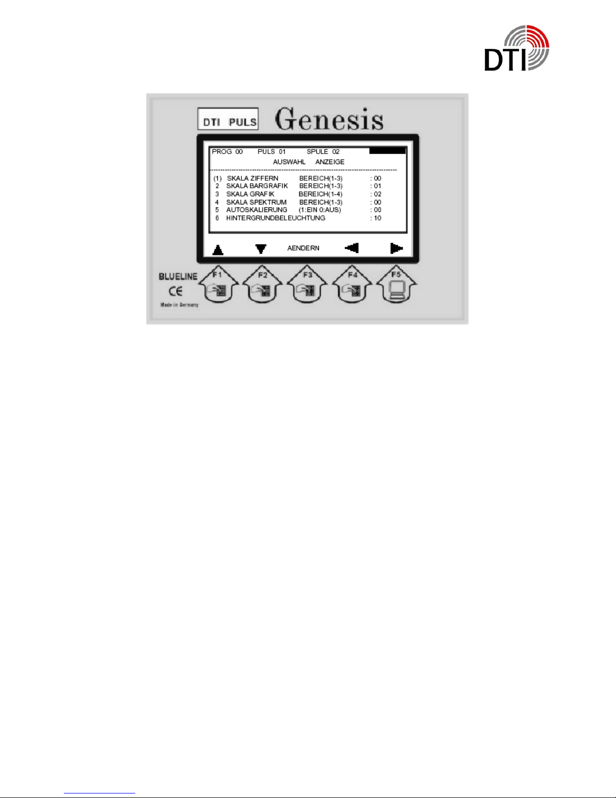
You press ‘F4’ and the Audio Menue will be displayed.
By the pushbutton F1/F2 you choose the function. By the pushbutton F3 you enter for
changing this parameter. By the pushbutton F1/F2 you change the value. By the
pushbutton F3 you save the setting.
If you have chosen to change the parameter by F3 you need to save by F3 because
otherwise you are not able to leave the menue or to make other changes.
By F4 you get back to the menue. By F5 you get back to the detection display. This is
the way to leave all menues.
Seite 15 von 31
Page 16

DTI GmbH & Co. KG
1. Audioverstärkung / Audio Amplifier
This parameter is identical with the active parameter and can be changed at
this place also.
2.
Lautsprecher / Loudspeaker
The internal loadspeaker can be switched of independently. Also the connector for the headphone is out of order when switched off. This function is to be
used in connection with the audio transmitter.
3. Audiosender / Audio Transmitter
The detector has an option for an audio transmitter which allows a wireless
transmittion to a wireless headphone. The autio transmitter can be put in additionall. It always comes together with the GENESIS.
4. Tondiskriminator / Tone Discriminator
By ton discriminator you switch the audio gnerator to the discriminator. So you
only will have an audio signal when the discriminator allows. If you activate
this function you should obey the display in any case because you could miss
objects because of the threshold.
5.
Beeper – Bediensignal
If you feel disturbed by the beeper you can switch it off. Warning signals will
not be switched off.
If you are back at the menue you can choose the menue Display by pushbutton
F3.
Seite 16 von 31
Page 17
DTI GmbH & Co. KG
1. Skala Ziffern / Scale Numbers
This parameter changes the range of display of the number display. The range
up to 1000 will be devided by this value.
2. Skala Bargrafik / Scale Bargraph
This parameter changes the range of the bargraph. Discriminator and all metal
display do have the same value. You are able to equal the display to the tone
behaviour.
3. Skala Grafik / Scale Graphic
This parameter changes the display range of detection record.
4. Skala Spektrum / Scale Spectrum
This parameter changes the display range of the spectrum.
5. Autoskalierung / Auto Scaling
This parameter adapts the scale automatically..
6. Hintergrundbeleuchtung / Backlight
This parameter changes the backlight of the display. By this option enormous
quantities of power can be saved.
If you are back in the menue you can choose the menue Coils (Spulen) by F2.
Seite 17 von 31
Page 18
DTI GmbH & Co. KG
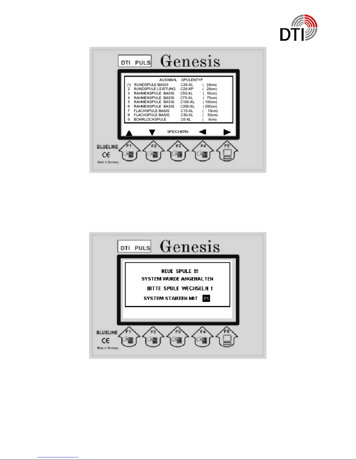
Here you choose the type of coil used. The puls power will be adapted for the coil
automatically if the setted power is too high. The type of coil has been printed to the
coil lable e. g. can be recognized by the diameter.
If you select the proper coil and press F3 this type will be stored. If you leave the
menue by F4 or F5 you will receive a message.
You will now be able to change the coil when the detector is switched on. Only if you
see this message, changing is allowed. Afterwards the instrument only needs some
time for stabelizing the coil. If you change from a higher power coil to a lower power
coil the power will be adapted, but not rized again automatically if you go back to a
higher power coil. So you should store the settings before changing.
Seite 18 von 31
Page 19
DTI GmbH & Co. KG
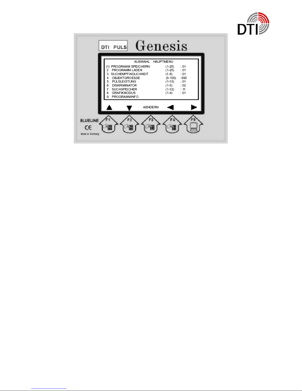
1. Programm Speichern / Program Storing
Below this menue you can store up to 25 programs. The chosen parameters
will be stored below the chosen program number and remain being stored
when the detector is switched off.
2. Programm Laden / Program Loading
Below this menue you can activate the stored program.
3. This paramter is identical to the active parameter and can be changed here.
4. This paramter is identical to the active parameter and can be changed here.
5. Below this parameter you can change the puls power.
6. This paramter is identical to the active parameter and can be changed here.
7. This paramter is identical to the active parameter and can be changed here.
8. At this menue you can change the active display. The less komponents the
faster the display speed.
1. Number Display, Bargraph, Spectrum and Detector Display
2. Number Display, Bargraph, and Detector Display
3. Number Display, Bargraph, and Spectrum
4. Number Display and Bargraph
9. Programminfo – Program Info allows viewing the program memories.
Seite 19 von 31
Page 20
DTI GmbH & Co. KG
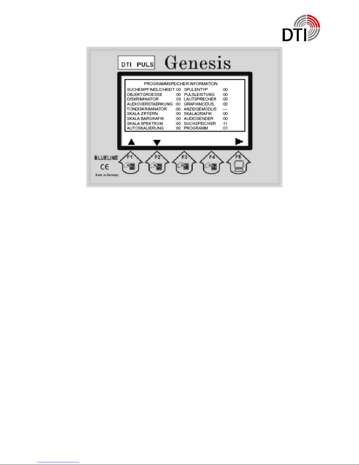
The menue „Programminfo“ – Program Info – shows all stored values of the program.
Here as an example Program 1 without stored values.
As discribed the searching memory is always 11.
By the pushbutton F1/F2 you can choose the program. By the pushbutton F5 you
leave the info side and you get to the detecting display.
Seite 20 von 31
Page 21

DTI GmbH & Co. KG
Operating the Detector
The first start should be made with the coil being in the air. So you will learn the behaviour of the detector for a known metal object. The coil is a sensitive receiver antenna for pulsing signals., which for example are transmitted by monitors, televisions
and short wave instruments. So no of this type of instruments should be switched on
near the test location. You may eliminate interference signals by turning or tipping up
of the coil. There shouln’t be any big metals within a distance of 1,5 – 2 m (boxes,
plates).
Place the coil (28 cm) in a fixed position. You should be able to reach it from all sides
with an object. Connect the coil. Please obey that the connector fits right. In case of a
loose contact the power amplifier can be destroyed.
Switch the detector on. After starting press pusbutton ‘F1’. The detector starts after a
few seconds with its factory settings and the operation display. The thermal starting
phase begins. A loaded rechargeable battery needs some minutes until it reaches to
its actually voltage. Also the electronic gets stabilized. Press the pushbutton ‘REFERENZ’ – reference – from time to time. There must be no metal in the near of the
coil otherwise this object will be stored in the compare memorie. Take an object of
your choice and move it to the coil. Comes the object in the detection area the
graphic display discribed under ‘Detectioin Display’ and the loudspeaker are showing
a response. Hold this point of detection in memorie. Take the object away und press
‘REFERENZ’.
Now repeat this test. You will recognize that the detection depth has increased.
The compare memory has been loaded with current values in air without object. Now
bring the object so close to the coil that the tone or the all metal display are near the
maximum. Now press the pushbutton ‘REFERENZ’ again. When you now try the object again you will recognize that you will have to get closer to get a signal.
This example shows you what happens when you press the pushbutton
‘REFFERENZ’ during working in the field.
Seite 21 von 31
Page 22

DTI GmbH & Co. KG
The characteristic of the soil and of the objects are being stored in the reference
memory and only changes of the intensity of signal will be detected. So you need to
do the reference (storing in reference memory) either in the air, with big distance to
the soil or when tilting the coil. Do the reference always in the air when you want to
compensate lowering of the battery voltage or other thermal relating drifting. Otherwise you will loose sensitivity. The reference should be done step by step. To pinpoint a strong signal move away from the point and go back step by step doing the
reference from time to time. Only the strongest signal will remain.
The display always starts with the active parameter ‘TONGENERATOR’ – Tone
Generator’ (150) above the pushbutton ‘F1’. Now press pushbutton ‘F3’. The value
will increase. Hold this pushbutton until the first click tones can be heart. Up to now
this value had to be produced by the object before you could hear a click. This value
now is the new threshold. The response is increased now. Test it with your test object. By the parameter ‘TONGENERATOR’ – Tone Generator – you adjust the
threshold of the acoustic signal.
Now choose the parameter ‚AUDIOVERSTAERKER’ – Audio Amplifier – by the
pushbutton ‚F1’. Here you multiply the number of clicks by the chosen value. If you
have a click rate of 10 clicks per second and your adjusted value is 10 you will get
100 clicks per second. Smallest detection changes can be heart by this feature. For
big objects this value should not be too high.
By this parameters you are able to double the range of distance compared to the
starting parameters. So you should do several tests with different test object and this
parameters. Especially when testing in the air in is recommended to use the reference after changes of parameters. Because of missing movement of the coil little
signal changes do have an influence.
All the parameter below the pushbutton ‘F1’ are adjustable online. They take effect
immediately. So it is possible to do changes above the detected object.
Seite 22 von 31
Page 23

DTI GmbH & Co. KG
Choose the ‚Audioverstärker’ - audio amplifier – and set the value to 1. To be able to
follow the effect a slow rise of the click tone is necessary.
Choose the parameter ‘SUCHSPEICHER’ – searching memory – by the pushbutton
‘F1’. This is an outstanding parameter. After start it always has the value 11. It always
will be stored in the program memory with this value. So the value has to be adjusted
after starting or loading a program in accordance to the current environment. The
detector has 64 searching memories. 33 auf these can be chosen. Every searching
memory is calculated out of 16 measured values. Each of this 16 values represent a
certain range of the detection signal. Tests have shown that the range of 11-15 is a
good average to grant a good functionality with all types of coils. The smaller this
value becomes the higher is the sensitivity for smaller objects. On the other hand the
reaction on the movement of the coil in the magnetic field of the earth and above the
soil in case of mineralization increases. Especially when the Audioverstärker – audio
amplifier it set to high values. A find adjustment in the lower range will have following
effects:
The Tongenerator – tone generator – doesn’t work in the range minimum to maximum any more, but reacts in the lower range or not at all. The bargraph display
shows the same behaviour. That doesn’t change if you use bigger objects. The spectrum further on shows the detection. You will recognize that from the left to the right
the first bars are not shown. For the 28 cm – 50 cm – coils an increasing of the
‘Suchspeicher’ – searching memory – is sufficient. It may be necessary to increase
the ‘Objektgröße’ – object size - . More later in this manual.
Please proceed following test:
Settings: ‘Suchspeicher’ – searching memory – 11 and ‘Audioverstärkung’ – audio
amplifier – 1. Take you test object and move it to the middle of the coil. Stop at the
first reaction and lower the ‘Suchspeicher’ – searching memory - .When lowering now
the click rate will increase what means that the searching depth increases. Increase
the ‘Suchspeicher’ – searching memory – and the reaction is visa versa. You should
do the same test in combination of ‘Suchspeicher’ and ‘Audioverstärker’ to observe
the reaction.
By the same way you can optimize the characteristics of the detector in the field. Either by detecting with the factory settings, better by adjusting using your test object
lying on the soil.
Seite 23 von 31
Page 24

DTI GmbH & Co. KG
A further parameter influencing the detecting results is the ‚SUCHEMPFINDLICHKEIT’ – searching sensitivity - . This setting should be only changed if very week detecting signals can be seen. Set all discussed parameters to factory settings and do a
reference (press ‘Referenz’).
Chose the parameter ‘SUCHEMPFINDLICHKEIT’ by pushbutton ‘F1’. All incoming
measured values will be influenced by this setting. Every change of the value has to
be confirmed by ‘Referenz’ for being token over to the memory. So every measured
value is multiplied if it has been multiplied in the ‘Audioverstärker’ - audio amplifier - .
That can cause instability if the values are too high. So it has to be checked in the
field which settings are useable.
For the test increase the value. The detector will now react showing the maximum
detecting display. Now you have to press ‘Referenz’ to pass this settings to the
memory. It is not recommendable to do this reference automatically because you
might not notice it or the coil might not be in the correct position. That could cause
week signals being eliminated (See ‘REFERENZ’). Combine the test with parameters
‘SUCHSPEICHER’ – searching memory - and ‘AUTIOVERSTAERKER’ – audio amplifier - . It is possible that you are not able to do the test up to the maximum of all
values in you test room. When doing the reference in a noisy environment or during
high settings of amplifying values it will happen that you eliminate some noise. For
that reason it is recommended to do 2 – 3 references. After a short time you will recognize a “wrong reference”. You should do the settings with various objects (size and
material). Also it is recommended to chose a reference object. This object should be
carried with when using the detector. So you can always compare the known behaviour with the behaviour at the field e. g. do a calibration to adapt the detector to the
soil. To detect coins or other flat objects the coil should be tipped and moved. The
response can be different depending on the location and position.
Seite 24 von 31
Page 25

DTI GmbH & Co. KG
Another parameter which influences the detecting is the ‘OBJEKTGROESSE’ – object size - .
Again set the parameters to factory settings. Chose the parameter ‘OBJEKTGROESSE’ – object size – by pushbutton ‘F1’. By this parameter you can filter
out small objects in low depth or big objects at the edges of the coil. You can compare that to following process:
You detect a coin, increase the height of the coil until the detection signal vanishes. A
little distance far away there are several coins. You will have a signal at the same
height. Go back to the single coin. If you now increase the ‘OBJECTGROESSE’ –
object size – at a height you had before until the signal vanishes, you will not see this
single coin any more, even if it was lying directly above a bigger object. A bigger object lying deeper can be filtered out in the same way. Big objects always have the
characteristic that they produce a constant signal above the complete area. Mineralized soils have the same characteristic and can be filtered out in the same way.
When testing this parameters do as with the ‘Suchspeicher’ - searching memory - .
The searching memory should always be set to 10 – 15.
By this parameter also frame coils will be calibrated. This parameters are working
with frame coils 50 cm – 200 cm x 100 cm. Do a reference when using this coils by
turning them by 90° - the active area showing in direction of air.
Now turn the active area to the soil. You will get a permanent signal. Increase the
height above the soil and check a bigger area. Now increase the ‘OBJECTGROESSE’ – object size – until the signal makes changes during movement
above the area.
Not again do a reference (coil showing to the air). Never do a reference with the active area of the coil showing to the soil. Do the calibration step by step – parameter
reference and parameter object size. The second possibility is you are receiving no
signal but the right part of the spectrum display shows a reaction. This corresponds
to the description below ‘Suchspeicher’ – searching memory - . Increase the ‘Objektgroesse’ – object size – until the detection signal shows up again. Do a reference
as described.
Seite 25 von 31
Page 26

DTI GmbH & Co. KG
This process can’t be done in a room except with the 50 cm coil. Frame coils have a
physical characteristic which absolutely have to be obeyed. The prime- and secondary field of the coil is an alternating field. The folded coil works like a transformator.
The segments inducts currents to each other. Depending on the form this current can
cause an inductive short circuit. This causes an increasing of the current up to a multiple of the normal current. It can happen – depending on the amplifying settings –
that the coil or the detector can be damaged.
So always spread out the coil before working.
Up to now the parameter ‘Pulsleistung’ - puls power - has not been discussed. In air
an increase of the puls power can be recognized only at big objects. The transmission field is not disturbed through its way through the air and is very stable for that
reason. The field can close very early. Small object causes only small disturbances
for that reason. With increasing power in the air the sensitivity for small objects decreases. Depending on the soil this effect will be seen up to about 50 cm too. This
applies to the high current detectors Nexus and Genesis. So it is always recommended to use the possibilities of the parameters ‘SUCHSPEICHER, AUDIOVERSTAERKER’, SUCHVERSTAERKUNG’ before increasing the puls power.
Test the change of increasing the power with your testing objects. Increasing the
power means to use more battery capacity.
Seite 26 von 31
Page 27

DTI GmbH & Co. KG
A further parameter which influences the detection is the ‘DISKRIMINATOR’ –
discriminator - .
Again set all parameter to factory settings. Chose now the parameter ‘DISKRIMINATOR’ by pushbutton ‘F1’. The discriminator has a range of 1-5. When sensitivity it set
to high values it is not possible to detect smallest and big objects in the same way.
The discriminator is based on an alloy algorithm. It is compareable to a beambalance. The possibility for distinguishing is based on the characteristics of the metals. Influential factors are its conductivity, shape, alloy, position and distance. Furthermore the type of soil is important. The electromagnetic field can be scattered,
directed or bended. Also there is an enormous volume of soil behind the detected
object which is detected and measured too. Perhaps here a bigger distance of the
coil to the soil or tipping the coil may help. It is essential that the detecting is reproduceable for a clear identification.
The sum of characteristics of different object may show a silver- or gold-signal depending on position, depth and soil. If you think about how many factors have to be
considered it is not surprising. Therefore test with different objects and necessary.
Bigger or massif precious metals will always show a negative result in the air, if they
are not alloyed. Even clearest gold will be alloyed by crystals and salts in the soil.
In setting 1 the discriminator is most sensitive to filter out iron and massif objects. A
golden ring (333, 485) will be detected clearly. After start the discriminator is set to 2.
Test the different settings with different materials (chains, rings, coins) and observe
the reaction of the number-, graphic- and spectrum-display. Mix the materials with
iron nails and other materials. By mixing, changing distance and movement you will
learn the reaction of discrimination.
By adding different materials which you move additionally you simulate different soils
e. g. beside lying objects. You should do this with different discriminators and combine it with the described parameters. Often it is also possible to recognize the metal
by following the course of detection. Ferromagnetic material produces a long floating
course over the complete diameter of the coil. Gold on the other hand produces a
lower tone at the edge of the coil.
Seite 27 von 31
Page 28

DTI GmbH & Co. KG
If you are in the fiel, test the soil first by your test object.
Switch you detector on. During this procedure the position of the coil is not important.
Start the detector by pressing ‚F1’
Wait for about 30 seconds.
Hold the coil into the air and press ‚Referenz’ – reference - .
Search for a week signal in the nearer environment. You also can use your test object if there is no signal. The test object lying on the soil should produce the same
signal as you have seen after start in the air.
Move the coil out of the detection area and increase the ‘Tongenerator’ – tone generator – until you heare the first click. Now again do a reference in the air. This is
necessary because the detector is still in stabilisation phase.
Go back to the detection area and lower the coil over the object until a detection can
be recognized. Now chose the ‘Suchspeicher’ – searching memory – and decrease
the value. The detection signal now will become stronger without changing the distance. Rise the coil until the signal becomes weaker again.
Chose the ‘Tongenerator’ – tone generator – and increase the value. The detection
signal will become stronger without changing the distance. The value should be set in
a way that a regular grow fainter of the tone can be heard when increasing the distance to the object. Now again do a reference in the air.
If you don’t have a detection signal duiring soil calibration, even using your test object, increase the ‚Suchspeicher’ – searching memory – or the ‚Objektgroesse’ – object size – until the signal comes up again. Here we have to do with mineralization or
a big flat object is lying below the coil.
As described before, always an increasing ob the ‘Objektgroesse’ – object size – is
necessary for the frame coils. This must be decided in the field.
Seite 28 von 31
Page 29

DTI GmbH & Co. KG
Battery Charger
The battery charger consists of following components:
1. International plug in charger 100V- to 240VAC 50/60 Hz
with changeable power adapters. The output voltage is
12VDC/1200mA
2. Processor controlled DC/DC converter for a input range of
12-24 VDC/10-20 VAC 1200mA
3. Connector cable for charging from the car board battery
When charging headphones please only use the charger There is no spezial
charger. Charging time is 15 hours. The headphone also can be charged using the connector cable for the car board battery.
The operation time of the headphone is 40-50 hours.
Charging the detector:
The detector has to be switched off when charging.
Connect the male connector of the DC/DC converter to the female connector of the
detector.
Connect the input connector the DC/DC converter to the car battery plug.
If there is battery power the LED’s will be switched on for a few seconds.
Now the yellow LED blinks. The processor is testing the input current. The red LED
also starts blinking. The switching charger will now increase its loading step by step.
The charging current will be controlled permanently. The processor analyses the type
of charging battery (Magic, Nexus, Genesis). The yellow LED is switched out or is
blinking shortly for corrections of the current. This complete procedure lasts a few
minutes. The detector will now be loaded. The red LED is blinking during loading.
After charging time (about 15 hours) the red LED switches off. And die green LED
shows the end of charging. The processor switches off the charging procedure.
Seite 29 von 31
Page 30

DTI GmbH & Co. KG
Warranty
The warranty time for this instrument is 2 years starting with the day of invoice. During the warranty time our service department will repair every failure of the instrument, which is depending on material or manufacturing. The necessary spare parts
will not be charged. Old parts will belong to us.
Exceptions concerning warranty are power and connection cable, rechargeable batteries. Lacks depending on non purpose usage and excluded also. Repairing those
failures will be charged. In case of an unfounded warranty claim the demanding person will be charged for all costs. Precondition for fulfilling the warranty duty is the
presentation of the invoice. The warranty is not transferable. A service does not extent the warranty time.
Danger
The detector must not be used for mine searching. Special mines react on disturbances of the earth magnetic field. This mines can be activated by a strong electromagnetic field. Mine fields are marked. Persons with pacemakers or other medical
instruments must not use this instrument. The electromagnetic field might influence
the rhythm.
Seite 30 von 31
Page 31

DTI GmbH & Co. KG
Seite 31 von 31
Inhaltsverzeichnis
DTI-Puls ..................................................................................................................................... 2
Assembling.................................................................................................................................4
Funktion ..................................................................................................................................... 5
Connecting ............................................................................................................................. 5
Setting to Operation ................................................................................................................... 7
Operation Display .................................................................................................................... 10
Tongenerator / Tone Generator:........................................................................................... 12
Suchspeicher / Searching Memory:...................................................................................... 12
Audioverstärker / Audio Amplifier:..................................................................................... 13
Diskriminator / Discriminator: ............................................................................................. 13
Objektgröße / Object Size: ................................................................................................... 14
Suchempfindlichkeit / Searching Sensitivity: ...................................................................... 14
Menue Options ......................................................................................................................... 15
Operating the Detector ............................................................................................................. 21
Battery Charger ........................................................................................................................ 29
Warranty................................................................................................................................... 30
Danger ...................................................................................................................................... 30
(C) Copyright: The copyright for this manual belongs to DTI. It must not be translated, copied, reproduced or published without DTI’s allowance.
DTI Detector Trade International GmbH & CO KG, Schloßstr. 65, D-40477 Düsseldorf
Service-phone for technical questions: 07000-DTI INFO = 07000-384 4636
 Loading...