

DTG Digital DTG M2, DTG M4 User Manual
ALL INFORMATION CONTAINED IN THIS DOCUMENT IS PROVIDED AS IS WITHOUT WARRANTY
OF ANY KIND. THE CREATOR OF THIS DOCUMENT , HEREINAFTER REFERRED TO AS THE
'WRITER' HEREBY DISCLAIMS ALL WARRANTIES, EXPRESSED, IMPLIED OR OTHERWISE,
INCLUDING WARRANTIES OF MERCHANTABILITY, FITNESS FOR A PARTICULAR PURPOSE, AND
NON-INFRINGEMENT OF INTELLECTUAL PROPERTY RIGHTS. THE WRITER DOES NOT ASSUME
OR AUTHORIZE ANY OTHER PERSON TO ASSUME FOR IT ANY OTHER LIABILITY IN CONNECTION
WITH THIS CONTENT. IN NO EVENT SHALL THE WRITER BE LIABLE TO THE READER OF THE
CONTENT OF THIS DOCUMENT, OR ANY SUBSEQUENT USER, INCLUDING THE ULTIMATE ENDUSER, IN CONTRACT, TORT, WARRANTY, STRICT LIABILITY, OR OTHERWISE FOR ANY SPECIAL,
INDIRECT, INCIDENTAL OR CONSEQUENTIAL DAMAGES, INCLUDING BUT NOT LIMITED TO, THE
COST OF LABOR, REQUALIFICATION, DELAY, LOSS OF PROFITS OR GOODWILL, EVEN IF THE
WRITER IS ADVISED OF THE POSSIBILITY OF SUCH DAMAGES. BY LOOKING AT THE CONTENT OF
THIS DOCUMENT THE READER AGREES THAT THEY HAVE READ AND AGREE TO THE ABOVE
CONDITIONS ENTIRELY.
USER GUIDE
REV. PR
DTG-M-T-1.0 DRAFT ONLY - NOT RELEASED
MANUAL
DTG M SERIES PRINTER

This page has been intentionally left blank

Important Notice
DTG M Series Maintenance Manual
No part of this product or publication may be stored, reproduced, copied, or
1.
transmitted in any form or by any means without the express permission of
IMPRESSION TECHNOLOGY.
The product and the contents of this publication may be changed at any time without
2.
prior notification.
IMPRESSION TECHNOLOGY has made the best efforts to keep this publication free
3.
from error, but if you find any uncertainties or misprints, please call us or the dealer
from where you bought this equipment.
IMPRESSION TECHNOLOGY shall not be liable for any damages or troubles resulting
4.
from the use or mis-use of this equipment or this manual either directly or indirectly.
I. Important
For Users in Europe 1.
IMPORTANT:
This is a Class A product approved for industrial environments. In some
environments this product may cause radio interference in which case you may
be required to take measures to re-locate this product.
For Users in the United States 2.
This equipment has been tested and found to comply with the limits for a Class A digital device,
pursuant to Part 15 of the FCC Rules. These limits are designed to provide reasonable protection
against harmful interference when the equipment is operated in a commercial environment.
This equipment generates, uses, and can radiate radio frequency energy and, if not installed and
used in accordance with the instruction manual, may cause harmful interference to radio
communications. Operation of this equipment in a residential area is likely to cause harmful
interference in which case the user will be required to correct the interference at his own expense.
Notice
Trademarks Mentioned in this Manual 3.
• DTG, WIMS, AOD, ACCULOK AND BMS are registered trademarks or product names of
IMPRESSION TECHNOLOGY.
• Centronics and BiCentronics are registered trademarks or product names of Centronics Data
Computer Corporation.
• Windows XP, Windows Vista, Windows 7 and MS- DOS are registered trademarks or product
names of Microsoft Corporation.
• Intel and Pentium are trademarks or registered trademarks of Intel Corporation.
• Other company and product names may be registered trademarks or product names.
•
i
ii
DTG M Series Maintenance Manual Warranty Limitations
II. Warranty
IMPRESSION TECHNOLOGY warrants part repair or replacement as a sole measure only if a failure
is found in the system or in the materials and workmanship of the product the seller produced.
However, if the cause of failure is uncertain or cannot be conclusively proved to be directly related
to defect in workmanship any part repair or replacement shall be solely at the discretion of
Impression Technology.
The warranty shall not apply to any direct or indirect loss, or compensation for the loss due to the
product that has been subject to misuse, neglect, or improper alternation whether directly or
indirectly.
ALL INFORMATION CONTAINED IN THIS DOCUMENT IS PROVIDED AS IS WITHOUT WARRANTY OF
ANY KIND. THE CREATOR OF THIS DOCUMENT , HEREINAFTER REFERRED TO AS THE 'WRITER'
HEREBY DISCLAIMS ALL WARRANTIES, EXPRESSED, IMPLIED OR OTHERWISE, INCLUDING
WARRANTIES OF MERCHANTABILITY, FITNESS FOR A PARTICULAR PURPOSE, AND NONINFRINGEMENT OF INTELLECTUAL PROPERTY RIGHTS. THE WRITER DOES NOT ASSUME OR
AUTHORIZE ANY OTHER PERSON TO ASSUME FOR IT ANY OTHER LIABILITY IN CONNECTION
WITH THIS DOCUMENT CONTENT. IN NO EVENT SHALL THE WRITER BE LIABLE TO THE READER
OF THE CONTENT OF THIS DOCUMENT, OR ANY SUBSEQUENT USER, INCLUDING THE ULTIMATE
END-USER, IN CONTRACT, TORT, WARRANTY, STRICT LIABILITY, OR OTHERWISE FOR ANY
SPECIAL, INDIRECT, INCIDENTAL OR CONSEQUENTIAL DAMAGES, INCLUDING BUT NOT LIMITED
TO, THE COST OF LABOR, REQUALIFICATION, DELAY, LOSS OF PROFITS OR GOODWILL, EVEN IF
THE WRITER IS ADVISED OF THE POSSIBILITY OF SUCH DAMAGES. BY LOOKING AT THE CONTENT
OF THIS DOCUMENT THE READER AGREES THAT THEY HAVE READ AND AGREE TO THE ABOVE
CONDITIONS ENTIRELY.
Limitations

DTG M Series Maintenance Manual
Section
Contents
1 Safety Instructions
Explains types of warnings, cautions and warnings labeled on the
printer
2 Product Overview
Explains the features, part names, and functions of the printer.
3 Specifications
Explains the specifications of the printer.
4 Parts Replacement
Explains the procedures of replacement and removal of the
service parts
5 Self-Diagnostic Mode
Explains the self-diagnostic functions of the printer.
6 Maintenance Mode2
Explains the maintenance mode2 of the printer.
7 Adjustment
Explains the adjusting procedures of the printer parts.
8 Maintenance
Explains daily maintenance of the printer.
9 Troubleshooting
Explains troubles that may occur when using the printer and
how to
10 Appendix
Explains the maintenance information and the exploded views
for this
III. About this
Manua
l
A. Purpose and Target Readers
This manual explains the preparations and procedures for operating the DTG M series printer.
This is a common User Guide for the DTG M series of printers. Unless specifically mentioned to the
contrary, the descriptions in this manual are common for all DTG M series models.
This manual is designed to assist the end user in the use, maintenance and general troubleshooting
of the DTG M series printers. Before using the DTG M series printer you are required to read and
fully understand the contents and directions in this manual.
B. Manual Configuration
iii
iv
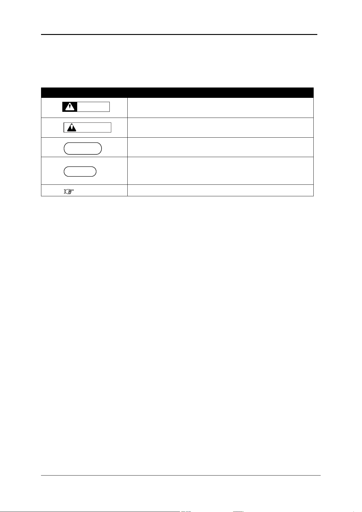
Symbol
Meaning
Must be followed carefully to avoid death or serious bodily
injury or catastrophic damage to your equipment.
Must be observed to avoid slight or moderate bodily injury or
damage to your equipment.
Contains important information and useful tips on the operation
of the product
Indicates useful tips for operating or understanding the
equipment or getting the best performance from your
equipment.
Indicates reference pages in this manual
WARNING
CAUTION
NOTE
TIP
C. Manual Notation
The following symbols are used in this manual for easier understanding of the information.

DTG M Series Maintenance Manual
GENERAL TABLE OF CONTENTS
v

vi
1. Safety Instructions ....................................... 1
1.1 Introduction ................................................................................... 2
1.2 Warnings, Cautions and Notes ...................................................... 2
1.3 Important Safety Instructions ........................................................ 3
1.4 Warning Label types and meanings ............................................... 6
1.4.1 Handling the Warning Labels .............................................................. 6
1.4.2 Locations of Warning Labels ............................................................... 7

DTG M Series Maintenance Manual
2. Product Overview......................................... 8
2.1 Introduction ................................................................................... 9
2.2 Features ......................................................................................... 9
2.2.1 High Resolution Image Quality ............................................................ 9
2.2.2 Ink Supply System ............................................................................... 9
2.2.3 Operation Efficiency Improvement ...................................................... 9
2.2.4 Operability Improvement .................................................................... 9
2.3 Part Names and Functions ........................................................... 10
2.3.1 Front Section .................................................................................... 11
2.3.2 Rear Section ..................................................................................... 13
2.3.3 WIMS ............................................................................................... 14
2.3.4 Operation Panel ................................................................................ 16
2.4 Printer Status ............................................................................... 19
2.4.1 Normal ............................................................................................. 19
2.4.2 Setup Menu ...................................................................................... 19
2.4.3 Changing Printer status .................................................................... 19
vii

vii
3. Initial Setup & Basic Operations ................. 20
3.1 Introduction ................................................................................. 22
3.2 Before you Get Started ................................................................ 22
3.2.1 Commit to Maintenance ................................................................... 22
3.2.2 Get to Know your M2 ........................................................................ 22
3.3 Choosing a Place for the Printer .................................................. 25
3.3.1 Installation Environment Requirements ............................................ 25
3.3.2 Required Space ................................................................................. 26
3.4 Minimum Computer Requirements ............................................. 28
3.5 Basic Operations .......................................................................... 29
3.5.1 Switching the Printer ON .................................................................. 29
3.5.2 Switching the Printer OFF. ................................................................ 31
3.5.3 Connecting the Printer to the PC ....................................................... 32
3.5.4 Confirming Default Settings .............................................................. 34
3.5.5 Performing a Head Clean from the Operation Panel .......................... 41
3.6 Initial Setup .................................................................................. 43
3.6.1 Removal of Shipping Tape ................................................................. 43
3.6.2 Initial Ink Fill Process - Colours .......................................................... 44
3.6.3 Initial Ink Fill Process – White ........................................................... 47
3.6.4 Loading Media for Printing ............................................................... 49

DTG M Series Maintenance Manual
3.6.5 Checking media height ..................................................................... 51
3.6.6 Performing a Nozzle Check Test Print ................................................ 53
3.6.7 Examining a Nozzle Check Test Print ................................................. 55
3.6.8 Bi-Directional (Bi-D) Adjustment ....................................................... 56
3.6.9 Installing & Using Printer Drivers ...................................................... 66
ix

x
4. Printing on Textiles with the DTG M2™ ....... 78
4.1 Introduction ................................................................................. 79
4.2 Prepare Your Image ..................................................................... 79
4.3 Garment Preparation ................................................................... 82
4.4 Load Garment to Platen / Platen to Printer ................................. 85
4.4.1 Put the garment onto the Platen ....................................................... 85
4.4.2 Adjust Printing Bed Height / Move Platen to the Top of Page position 85
4.5 Print Your Image .......................................................................... 85
4.6 Post-Printing ................................................................................ 86
4.7 Cancelling a Print Job ................................................................... 86
4.7.1 Introduction ..................................................................................... 86
4.7.2 Cancelling the Print Job .................................................................... 87
4.7.3 Re-starting the Printer after Cancelling a Print Job ............................ 87

DTG M Series Maintenance Manual
5. General Care & Maintenance of your DTG M2
88
5.1 Introduction ................................................................................. 90
5.2 Execute a Print Head Clean at the end of production ................. 90
5.3 Run the Epson Nozzle Check utility each day before starting
production ........................................................................................... 90
5.4 Maintaining the Ink System ......................................................... 90
5.4.1 Accessing the Capping Station .......................................................... 90
5.4.2 Cleaning the Flushing Tray ................................................................ 92
5.4.3 Cleaning the Wiper and Head Cap ..................................................... 93
5.4.4 Manual Print Head Guards Clean ...................................................... 94
5.4.5 Parking the Print Head...................................................................... 95
5.4.6 Emptying the waste ink container ....................................................... 96
5.5 Other Maintenance Items ........................................................... 97
5.5.1 Powerful Head Cleaning ................................................................... 97
5.5.2 Clean the CR Encoder Strip .............................................................. 101
5.5.3 Clean the CR Guide (X Rail) ............................................................. 104
5.5.4 Clean the CR Drive Belt, Roller and Pulley ........................................ 105
5.6 General Care .............................................................................. 106
5.6.1 Environment ................................................................................... 106
xi

xii
5.6.2 Clean your DTG M2™ ...................................................................... 106
5.6.3 Avoid White Ink Separation ............................................................ 106
5.6.4 Replace WIMS filter ........................................................................ 107
5.6.5 Empty & Wash White Ink Canister .................................................. 107
5.6.6 Ink Levels........................................................................................ 107
5.6.7 Pre-Treat garments away from the printer ...................................... 107
5.6.8 Flushing the printer ........................................................................ 108
5.6.9 Installation Environment Requirements .. Error! Bookmark not defined.
5.6.10 Required Space .................................... Error! Bookmark not defined.
5.7 Minimum Computer Requirements . Error! Bookmark not defined.
5.8 Basic Operations .............................. Error! Bookmark not defined.
5.9 Transportation of Printer ........................................................... 116

DTG M Series Maintenance Manual
6. Troubleshooting ....................................... 117
6.1 Introduction ............................................................................... 118
6.2 Troubleshooting with Error Messages ....................................... 118
6.2.1 Operation Status ............................................................................ 119
6.2.2 Errors with Message ....................................................................... 120
6.2.3 Data Errors ..................................................................................... 122
6.2.4 Command Errors ............................................................................. 123
6.2.5 Errors Requiring Reboot .................................................................. 124
6.3 Troubleshooting Without Error Messages ................................. 133
6.3.1 Initial Operation Problems .............................................................. 133
6.3.2 Printing Problems ........................................................................... 136
6.3.3 Noise Problems ............................................................................... 149
6.3.4 Problems with Curing / Washing ..................................................... 150
6.3.5 Other Problems .............................................................................. 152
xiii

xiv
7. Appendix ................................................. 153
7.1 Product Specifications ............................................................... 154
7.1.1 Main Unit Specifications ................................................................. 154
7.1.2 Print Operation Specifications ......................................................... 154
7.1.3 Printer physical specifications ......................................................... 155
7.2 Interface Specifications ............................................................. 156
7.2.1 USB Interface Specifications ............................................................ 156
7.2.2 Network Interface Specifications ..................................................... 157
7.3 Options/Supplies List ................................................................. 157
7.3.1 Options .......................................................................................... 157
7.3.2 Supplies .......................................................................................... 158

1
DTG M Series Maintenance Manual Product Overview
1. Safety Instructions
1.1 Introduction ................................................................................... 2
1.2 Warnings, Cautions and Notes ....................................................... 2
1.3 Important Safety Instructions ........................................................ 3
1.4 Warning Label types and meanings ............................................... 6
1.4.1 Handling the Warning Labels ............................................................... 6
1.4.2 Locations of Warning Labels ................................................................. 7
2
Product Overview DTG M Series Maintenance Manual
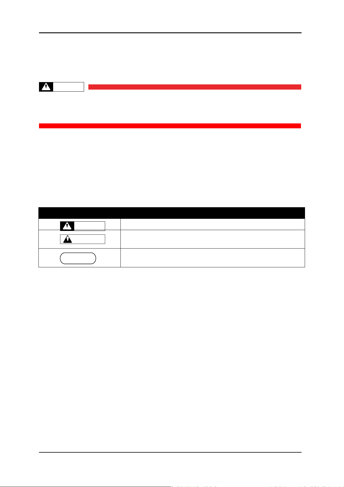
Safety Terms
Details
Must be followed carefully to avoid death or serious bodily injury
Must be observed to avoid slight or moderate bodily injury or
damage to whole or part of the product
Contains important information and useful tips on the operation of
the product
TABLE 1-1 SAFETY TERMS
WARNING
CAUTION
WARNING
NOTE
1.1 Introduction
This chapter explains the meaning of safety terms for personnel who install, operate, or maintain
this equipment, important safety instructions, and the warning labels attached to the equipment.
Make sure to follow all instructions and warnings on this manual when installing, operating,
or maintaining the equipment.
1.2 Warnings, Cautions and Notes
Safety terms in this manual and the contents of warning labels attached to the printer are
categorized into the following three types depending on the degree of risk (or the scale of accident).
Read the following explanations carefully, and follow the instructions in this manual.

3
DTG M Series Maintenance Manual Product Overview
WARNING
1.3 Important Safety Instructions
General safety instructions that must be observed to use the equipment safely are explained below.
Do not place the printer in the following areas. Doing so may result in the printer tipping or 1.
falling over and causing serious injury.
Unstable or loose surfaces
Angled surfaces
Areas subject to vibration by other equipment
Do not stand on or place heavy objects on your printer. Doing so may result in the printer 2.
tipping or falling over and causing injury.
Do not cover the ventilation hole of your printer with cloth, such as a blanket or table cloth. Doing 3.
so could obstruct ventilation and cause fire.
Do not place the printer in humid and dusty areas. Doing so may result in electrical shock or fire. 4.
Make sure to use the power cable packed with the printer you purchased. Not doing so may 5.
result in electrical shock or fire.
Do not use the power cable if it is damaged in any way. Doing so may result in electrical shock 6.
or fire.
Do not insert or drop metal or objects which are easily combustible through the openings such 7.
as the ventilation hole of your printer. Doing so may result in electrical shock or fire.
Do not operate the printer if it has been contaminated by foreign substances or liquid spills as 8.
doing so may result in electrical shock or fire. Immediately turn off the power switch,
disconnect the power plug from the electric socket, and contact your authorized DTG Dealer.
Make sure to use only the specified power supply (AC 100 V - 120 V or AC 220 V - 240 V). If the 9.
power supply other than the specified voltage is used, it could cause an electric shock and fire.
Take power for the plotter directly from the power socket (AC 100 V - 120 V or AC 220 V - 240 10.
V). Do not use complex multiple plugs on the same socket. This could generate heat and might
cause fire.
Make sure that the following is performed before parts replacement. 11.
Turn off the power of the printer.
Remove the power cable from the power outlet. Not doing so may cause electric shock or
damage to the electric circuit.
Unplug the cables connected to the printer. Failure to do so could result in damage to the
printer.

4
Product Overview DTG M Series Maintenance Manual
CAUTION
Pay attention to the following when handling the power cable: 1.
Do not do anything forcefully (e.g. pull, bend, twist) on the power cable
Do not place heavy objects on the power cable
Do not route the power cable near heat sources
Pay attention to the following points while handling the power supply plug. Not going so may 2.
result in electrical shock or fire:
Make sure that the power cable / plug is not contaminated by no foreign substances such as
dust etc.
Make sure that the power plug is correctly connected to the power socket.
Pay attention when handling inks so that ink does not get into the eyes or spill on your skin. If 3.
the ink does get into eyes or onto skin, immediately wash the affected area with water. The
inks may cause mild skin irritation and/or inflammation of the eyes. Consult with medical
personnel in the case of any severe reaction.
Be careful to ensure that fingers are not caught in the opening when lifting and closing the top 4.
cover of the printer.
Do not use strong solvents such as thinners, benzene or alcohol on the printer. These products 5.
may damage the paint on the printer.
Take care that moisture does not enter the printer. There is a risk of a short circuit of the 6.
electrical circuit(s) within the printer if this occurs.
Ensure that the printer is always kept in a horizontal position, even whilst it is being lifted or 7.
moved.
Do not leave the printer on a slanted surface. Do not leave the printer upside down. Doing so 8.
may cause ink leakage and / or trouble that cannot be restored, as the printer is originally
assembled in the factory with a high accuracy of 1/100 mm.
Ensure all packing materials are removed from the printer before lifting from it’s crate. If the 9.
printer is lifted with materials attached, it may slip from the hands and be damaged.
Assembling and disassembling of the printer are possible only for the parts that disassembling 10.
procedures are shown in this manual, and should be undertaken only by DTG authorized and
trained professionals. Do not disassemble any frame parts or parts that disassembling
procedures are not shown in this manual. Doing so may cause trouble that cannot be restored,
as the printer is originally assembled in the factory with a high accuracy of 1/100 mm.
Do not touch the elements on the circuit board with bare hands. Doing so may cause static 11.
electricity and cause catastrophic invisible damage.
Do not press the transparent film on the damper assembly with your hands. Doing so may 12.
discharge the ink filled inside the damper assembly or damage the pressure valve.
Be careful not to damage the transparent film on the damper assembly. 13.
Do not touch the nozzle plate of the print head, keep free from dust. 14.
There is ink in the tubes throughout the printer. Be careful that the ink is not spilled from any 15.
tube outlet onto the printer or items close to the printer.

5
DTG M Series Maintenance Manual Product Overview
If you need to operate the printer with the cover removed for maintenance or repair, be careful
16.
not to get injured by any moving parts.
Never lubricate the printer mechanism with anything other than that designated by Impression 17.
Technology. Doing so may damage the parts or shorten the lifetime.
If the power board assembly needs to be removed, remove the power cable and wait for 5 18.
minutes or more before taking it out; this will discharge the residual electrical charge of the
electrolytic capacitor. Touching the board before the capacitor discharges may cause electric
shock or death.
When connecting or removing an FFC type cable on a main board assembly connector, make 19.
sure to connect or remove the cable perpendicular to the connector. Connecting or removing at
a slant may damage, break or short-circuit the inner terminal of the connector and may damage
the components on the board.
When connecting or removing an FFC type cable on the CR board assembly connector, make 20.
sure to connect or remove the cable perpendicular to the connector. Connecting or removing at
a slant angle may damage, break or short-circuit the inner terminal of the connector. That may
damage the components on the board.
Make sure there is sufficient space around the printer when performing maintenance work. 21.
Maintenance must be done by more than two person for the following work. 22.
When disassembling or reassembling the product and the optional stand
When packing the printer for transportation
6
Product Overview DTG M Series Maintenance Manual
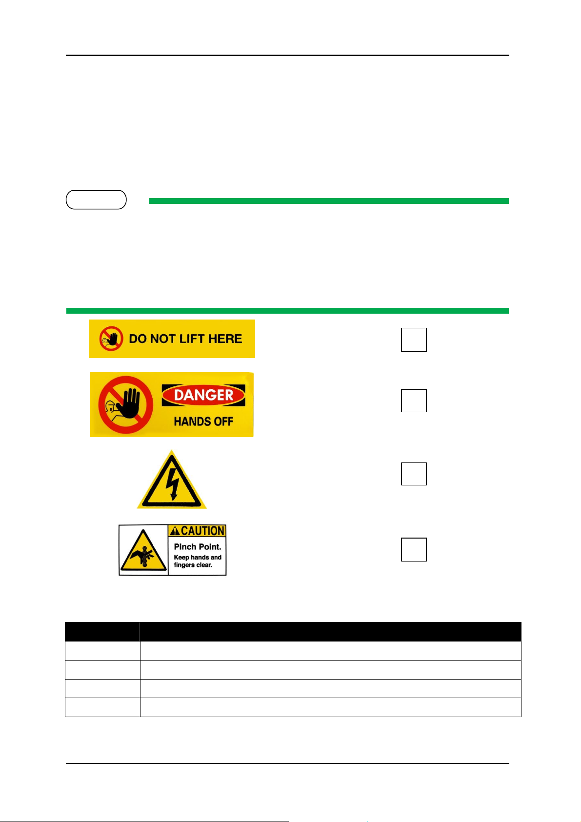
Ref
Warning Label Type
A
Using this area as a lift point will cause damage to the printer.
B
Do not touch anything in this area unless instructed.
C
Dangerous voltages present in this area.
D
Fingers may be trapped and ripped off in this area.
TABLE 1-2 WARNING LABEL TYPE
A
B
C
D
NOTE
1.4 Warning Label types and meanings
The handling, attachment locations, and types of warning labels are explained below.
Warning labels are attached to areas where care should be taken. Read and understand the
positions and contents thoroughly before maintenance operation.
1.4.1 Handling the Warning Labels
Make sure to note the following when handling the warning labels.
Make sure that all warning labels can be recognized. If text or illustrations cannot be seen 1.
clearly, clean or replace the label.
When cleaning warning labels, use a cloth with water or neutral detergent. Do not use any 2.
solvent or gasoline products.
If a warning label is damaged, lost, or cannot be recognized, replace the label. 3.
7
DTG M Series Maintenance Manual Product Overview
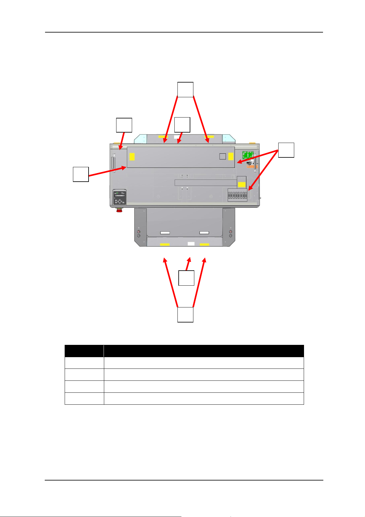
Ref
Warning Label Type
A
Using this area as a lift point will cause damage to the printer.
B
Do not touch anything in this area unless instructed.
C
Dangerous voltages present in this area.
D
Fingers may be trapped and ripped off in this area.
B
C
D
B
A D A
1.4.2 Locations of Warning Labels
The locations of warning labels are shown below.

8
Specifications DTG M Series Maintenance Manual
2. Product Overview
2.1 Introduction ................................................................................... 9
2.2 Features ......................................................................................... 9
2.2.1 High Resolution Image Quality ............................................................. 9
2.2.2 Ink Supply System ................................................................................ 9
2.2.3 Operation Efficiency Improvement ....................................................... 9
2.2.4 Operability Improvement ..................................................................... 9
2.3 Part Names and Functions ........................................................... 10
2.3.1 Front Section ...................................................................................... 11
2.3.2 Rear Section ....................................................................................... 13
2.3.3 WIMS ................................................................................................ 14
2.3.4 Operation Panel ................................................................................. 16
2.4 Printer Status ............................................................................... 19
2.4.1 Normal .............................................................................................. 19
2.4.2 Setup Menu ....................................................................................... 19
2.4.3 Changing Printer status ..................................................................... 19

DTG M Series Maintenance Manual Product Overview
2.1 Introduction
This chapter explains the features, part names, and functions of the printer.
2.2 Features
The features of the printer are explained below.
2.2.1 High Resolution Image Quality
This model uses the drop on-demand piezo head with a high performance coated nozzle plate.
The ability to eject >40pl droplet size enables excellent white ink delivery.
2.2.2 Ink Supply System
This model uses a microprocessor controlled pressurised color ink supply system and a patented
White Ink Management System (WIMS) utilising high performance brushless motors designed to
provide trouble free, accurate white ink delivery at all times.
2.2.3 Operation Efficiency Improvement
Loading media onto the media platens is done away from the printer and then slipped into the
ACCULOK platen locating and holding system.
2.2.4 Operability Improvement
The simple and intuitive GO/NO GO system uses two high brightness LED’s to indicate to the user
whether or not the printer is ready to receive a print job.
Sending a print when either LED is not green will result in a failed print job.
9
10
Specifications DTG M Series Maintenance Manual
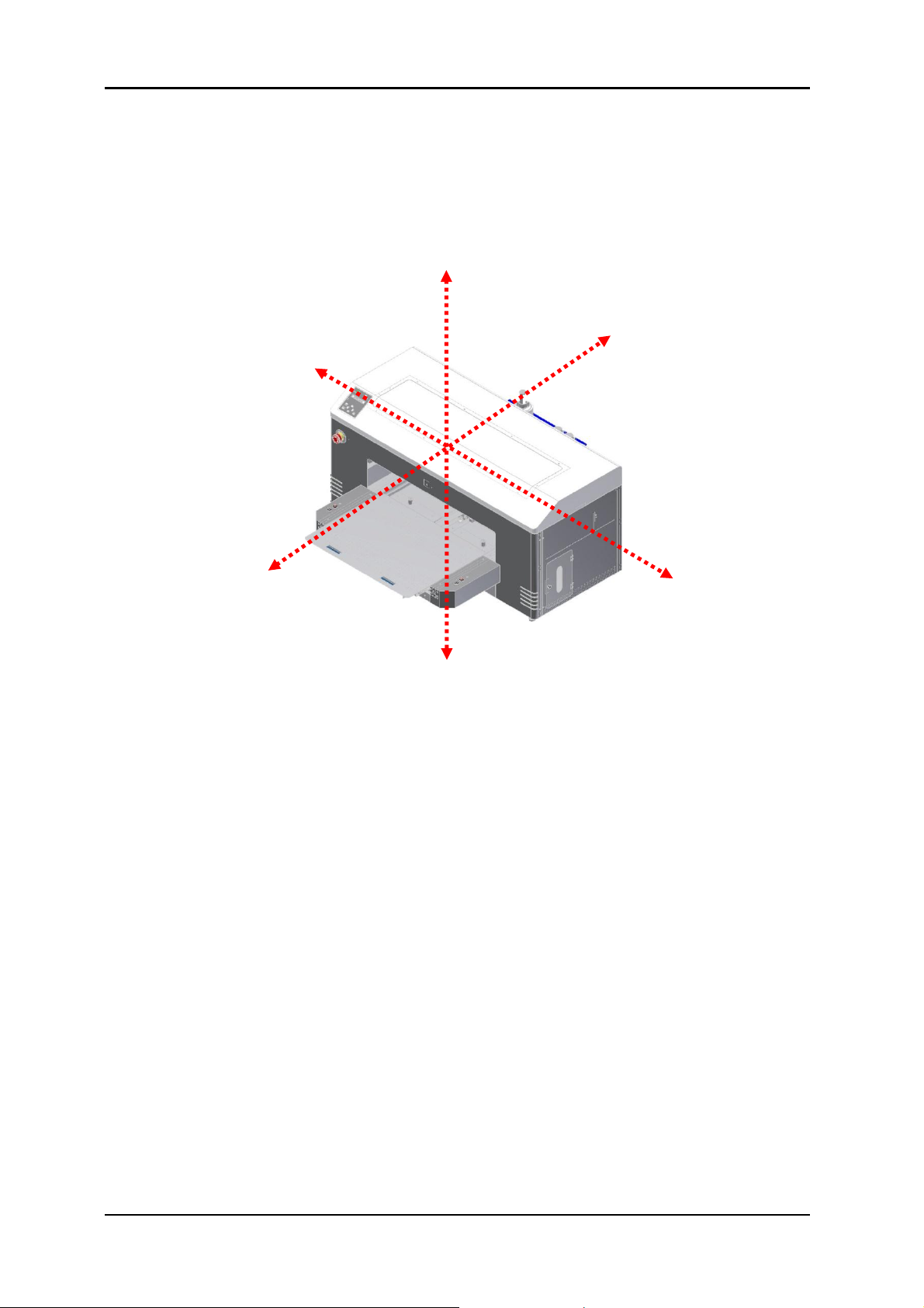
Left
Upper
Rear
Front
Right
Lower
FIGURE 2-1 PRINTER ORIENTATION
2.3 Part Names and Functions
Part names and functions are explained in this section.
For the directions described in this document, refer to the following orientation figure:
DTG M Series Maintenance Manual Product Overview
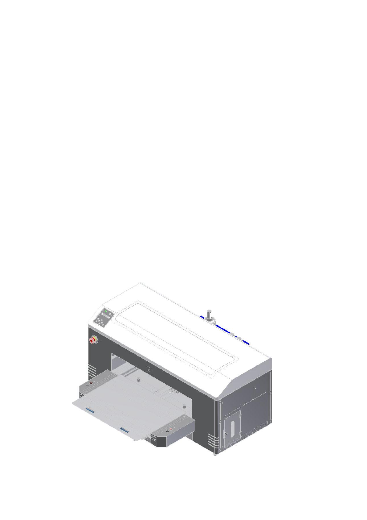
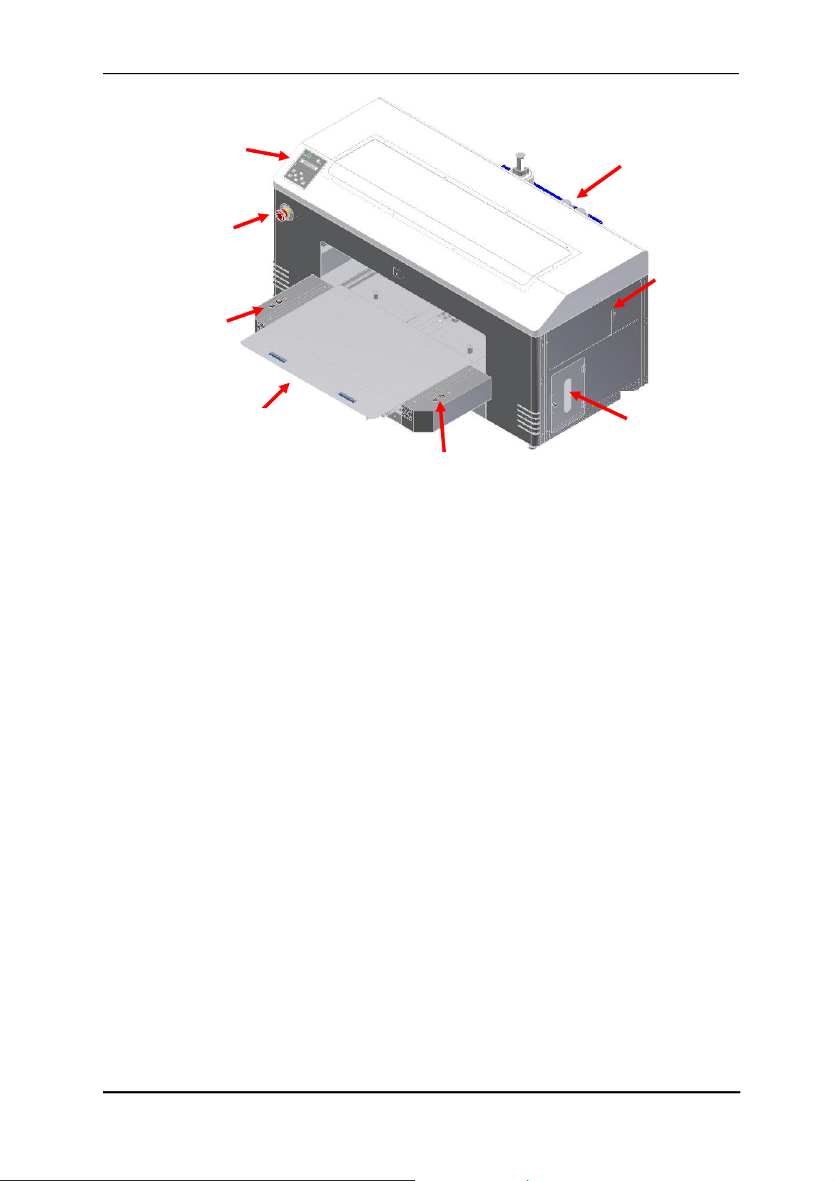
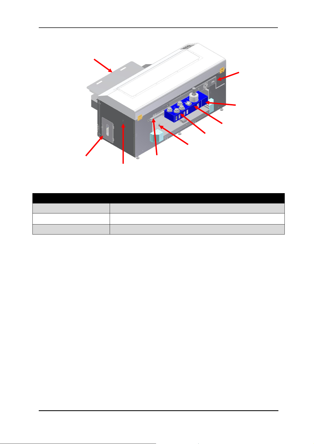
FIGURE 2-2 PRINTER
FRONT SECTION PARTS
Emergency stop
LCD and keypad
Bed up/down
buttons &
status light
Bed Load/eject
buttons &
status light
Waste ink
access
Pressure reset
and status light
WIMS &
Bulk ink
system
Media
tray
2.3.1 Front Section
11

12
Specifications DTG M Series Maintenance Manual
Name
Function
Emergency stop
This button removes mains power from the printer in an emergency.
Bed UP button
This button causes the motorised bed to move upwards and decrease the gap
between the print head and media.
Bed DOWN button
This button causes the motorised bed to move downwards and increase the
gap between the print head and media.
Bed STATUS light
This solid state lamp indicates the status of the bed height and it’s relation to
the head safety beam.
GREEN indicates that the media is at, or lower than, the optimum print height.
RED indicates that the media is at, or higher than, the recommended safe
print height.
AMBER indicates that the media height/head protection system has been
disabled and only the bed down button can be used. This mode is accessed by
depressing the bed UP button and the bed DOWN button at the same time
Bed LOAD button
This button causes the printer to move the bed into the start of print position
in which the top most area of the bed will be aligned with the top of the
selected print position.
Bed EJECT button
This button causes the printer to move the bed into the end of print position
in which the bottom most area of the bed will be situated in the entry point of
the printer.
Bed STATUS light
GREEN indicates that the bed is loaded in to the printer and the printer is
ready to print.
RED indicates that the bed is NOT loaded in to the printer and the printer will
not be able to print correctly, an error will occur if a print is sent to the
printer when the bed status light is red.
AMBER indicates either that the printer is still powering up or that the BOSS
board is in diagnostic mode. This mode is accessed by holding down both bed
EJECT and bed LOAD buttons at turn on. Diagnostic mode should only be
accessed under the direct instruction of an Impression Technology
authorized DTG technician.
Pressure Reset
Button & Status
Light
The CMYK pressure system comprises a pressure control board, DC motor
driven diaphragm pump and pressure limit switch. There is also a reset
switch, warning beeper and a status indicator light. The system will pump for
a limited time to build the correct CMYK ink pressure level, if this is not
achieved the indicator lamp will flash red, the beeper will sound and the
pump will stop. This is to alert the user to a pressure loss. This can be reset by
briefly pressing the reset switch which will cause the pump to start again and
the light will go yellow. When the correct pressure is reached and all is well
the indicator lamp will pulse green.
TABLE 2-1 PRINTER FRONT SECTION PART FUNCTION
DTG M Series Maintenance Manual Product Overview
Name
Function
AC mains power inlet
For inserting the mains power cable plug.
Network interface connector
Connector to connect a network interface cable.
USB cable connector
Connector to connect a USB cable.
FIGURE 2-3 PRINTER
REAR SECTION PARTS
Media tray
Mains
inlet
Ethernet and
USB
WIMS unit
WIMSPump
and stirrer
Colour ink
bottles
Optical
sensor
Waste ink
access
Pressure reset
and status light
2.3.2 Rear Section
TABLE 2-2 PRINTER REAR SECTION PARTS FUNCTION
13
14
Specifications DTG M Series Maintenance Manual
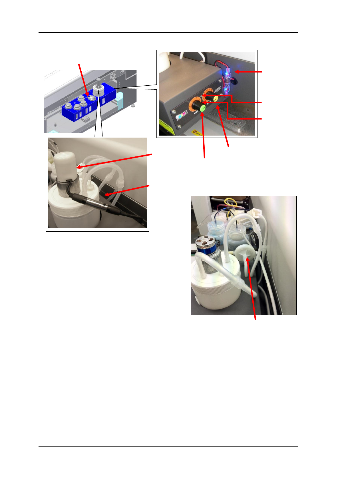
FIGURE 2-4 WIMS PARTS
Stirrer Power
connection /
indicator
Stirrer
Motor
WIMS Pump
WIMS mode
button
WIMS
Status Light
WIMS Rest
Setting
WIMS Stir
Setting
WIMS Power
Connection /
Indicator
WIMS Filter
2.3.3 WIMS
 Loading...