

FCC Caution.
This device complies with part 15 of the FCC Rules. Operation is subject to the following two
conditions: (1)This device may not cause harmful interference, and (2) this device must accept
any interference received, including interference that may cause undesired operation.
Any Changes or modifications not expressly approved by the party responsible for compliance
could void the user's authority to operate the equipment.
Note: This equipment has been tested and found to comply with the limits for a Class B digital
device, pursuant to part 15 of the FCC Rules. These limits are designed to provide reasonable
protection against harmful interference in a residential installation. This equipment generates
uses and can radiate radio frequency energy and, if not installed and used in accordance with the
instructions, may cause harmful interference to radio communications. However, there is no
guarantee that interference will not occur in a particular installation. If this equipment does
cause harmful interference to radio or television reception, which can be determined by turning
the equipment off and on, the user is encouraged to try to correct the interference by one or
more of the following measures:
-Reorient or relocate the receiving antenna.
-Increase the separation between the equipment and receiver.
-Connect the equipment into an outlet on a circuit different from that to which the receiver
is connected.
-Consult the dealer or an experienced radio/TV technician for help.
* RF warning for Portable device:
The device has been evaluated to meet general RF exposure requirement. The device can be used
in portable exposure condition without restriction.
OFF
WIRE LESS MI CROPH ONE
CH4
RF
CH3
CH2
AF
CH1
VOL
OFFOFF
CHA
CH4
RF
CH3
CH2
AF
CH1
CHB
CH8
RF
POWER
CH7
CH6
AF
CH5
VOLVOL
WIRELESS MICROPHONE SYSTEM
USER GUIDE
Thank you for purchasing the Wireless Mi crophone System and cong ratulations on your choice.
The model is loaded with top professional operating features and is the best price value available in UHF wireless
systems.
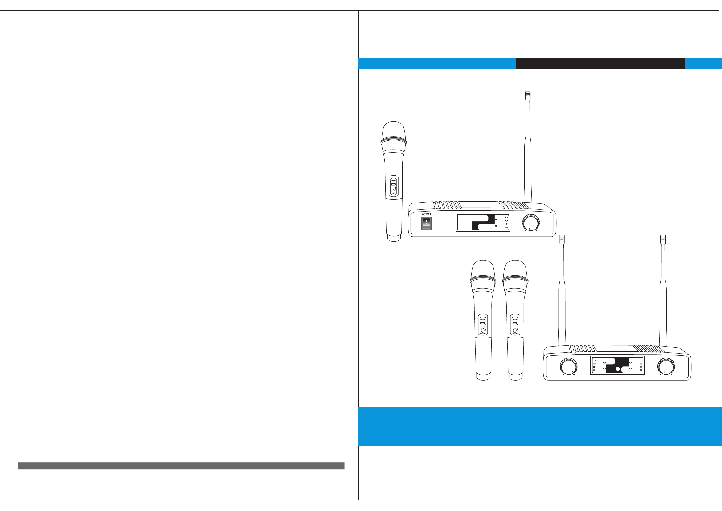
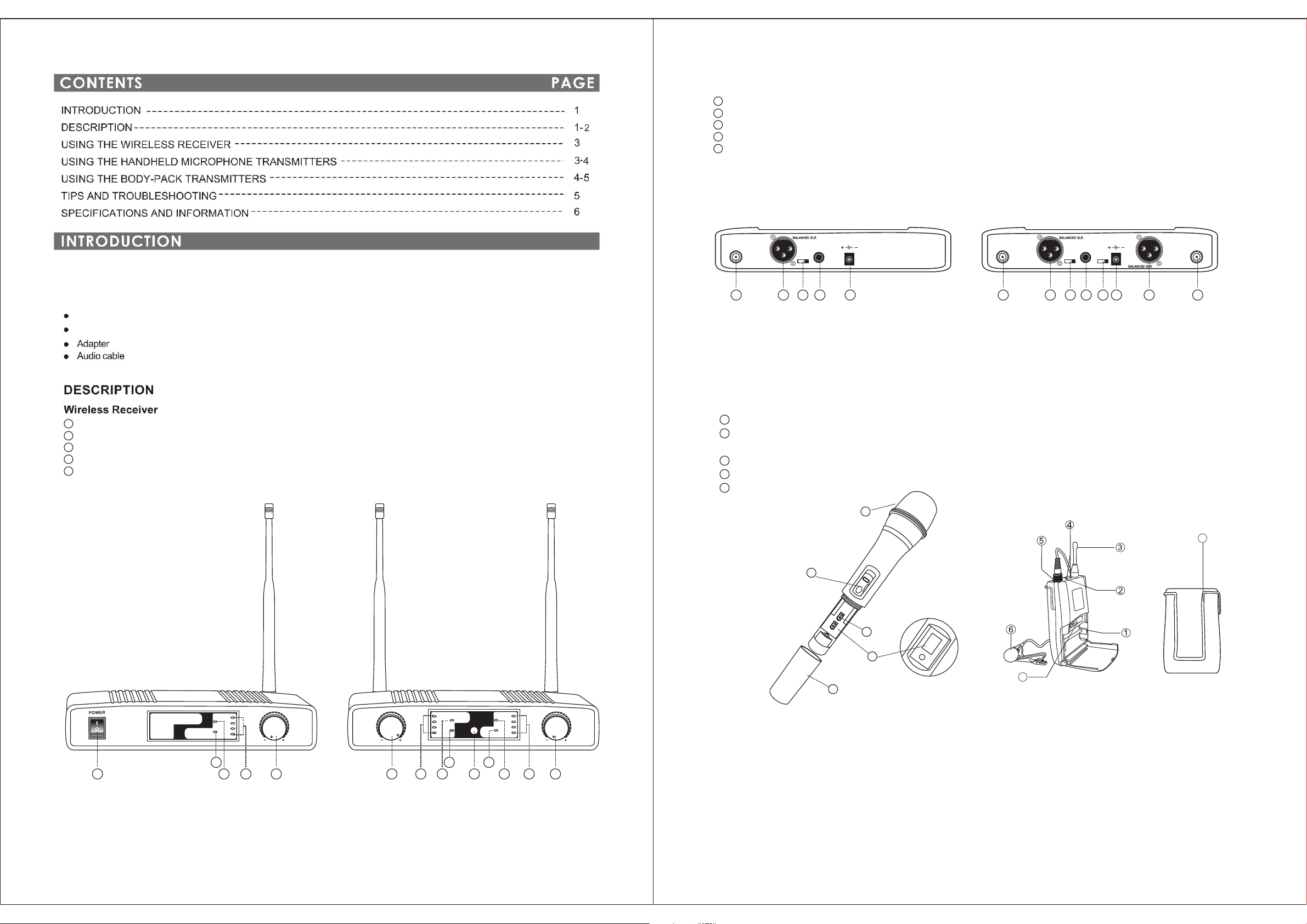
This Wireless System contains the following components:
4 frequencies selectable each channel wireless receiver
REAR (FIGURE 2)
6
Antenna s-to re ceive s ignals from the tr ansmi tter
7
Balance -Outp ut
8
Frequen cy Chan nel Selecting Sw itch
9
Unbalan ced Audi o and Mix ed Output
10
Power-D C Input
8 frequen cies se lecta ble trans mitte r
1
Volume Con trol
2
Channel I ndica tor
3
RF LED-In dicat es stre ngth of incoming R F signa l
4
Audio LED -Indi cates strength o f incom ing aud io signal
Power/O N/OFF s witch
5
ANT.B
CHANNEL
4 3 2 1
MIXED OU TPUT
4 3 2 1
DC IN
12VDC
ANT.B ANT.A
CHANNEL CHANNEL
8 7 6 5 4 3 2 1
MIXED OU TPUT
DC IN
12VDC
6 6 67 7 78 89 1098 10
FIGURE 2
Handheld Microphone Transmitter (FIGURE 3)
1 Change to H ead
2 Power ON/ OFF and M UTE ON/ OFF Switch.
When this r ed ligh t is glow ing, you ha ve 20 min utes or l ess of useful oper ating t ime; change the ba ttery.
3 2 AA Al kaline Battery. Prov ides powe r to the mi croph one transmitte r. Typical batte ry life i s 8 hours.
4 Battery C over. Take off th e batte ry cover for two 1.5 V alkal ine batteries.
5 Channel S elect or
1
8
8
WIRE LESS MI CROPH ONE
OF
2
F
8
8
3
8
C
.
H
AN
N
EL
5
S
ELECT
7
7
4
CHA
CH4
RF
CH3
CH2
AF
CH1
VOL
4
2
3
1
CH4
RF
CH3
CH2
AF
CH1
4 4
2 23 3
CHB
CH8
RF
POWER
CH7
CH6
AF
CH5
VOLVOL
Body-Pack Transmitter (FIGURE 4)
1 .Battery Compartment.
2.Power and Low Battery Indicator. When this red light is glowing,you have 20 minutes or less of useful operating time;
55
11
change the battery.
FIGURE 3
FIGURE 4
3. Antenna
4.Power and Mic MUTE ON/OFF Switch.
FIGURE 1
5.Microphone Input Connector. Connector provides connection to a variety of lavaliere and headset microphone cables.
6.Lavalier Microphone. Condenser lavaliere microphone supplied with a mount that clips onto a tie,lapel,or acoustic instrument.
7.Channel Selector.
8. Belt Clip.
PAGE 1
PAGE 2

1. Clip the body pack transmitter to your belt or guitar strap.
2. Connect the lavaliere microphone, headset or instrument adapter cable to the body-pack transmitter.
3. Select the transmitter to the right frequency.
4. Turn the transmitter POWER switch ON and MUTE switch OFF.
5. Check the RF Signal Indicator on the receiver to see if the RF signal is being received.
6. Begin speaking or playing your instrument.
7. During the performance or presentation, slide the MUTE ON/OFF switch to the ON position when the system is not being used.
8. When the performance or presentation is over, slide the transmitter MUTE ON/OFF switch to ON position and Power ON/OFF
switch to the OFF position to conserve battery power.
3. Insert two 1.5 VAA alkaline batteries into the battery compa rtment. Two fresh 1.5V alkaline batter ies should typi cally provide 8
hours of perfor mance time. Two fully cha rged 1.2V Nicad batte ries (1800 mA) should provide 12 hours of performa nce time.
When the LOW BATTERY light on the transmitter turns on, you have 20 minutes of less of useful battery life remai ning.
Change the batt ery at you fir st opportunity.
IMPORTANT: Carbon-zinc and zinc-chloride will not provi de adequate pow er and are not recommended.
4. Sl ide th e bat te ry cov er ba ck on to th e m ic bo dy.
1. Slide the tran smitter Power ON/OFF switch to the OFF position.
2. Pull up on the OPEN side of the bat tery compartment cover, flip it open, as shown in FIGURE 8.
3. Insert fresh 1.5VAA alkaline batteries into the battery com partment as sho wn in Figure 8. Two 1.5VAA batteries sh ould provide 8
hours of perfor mance time. Whe n the red LOW BATTERY lig ht on the tran smitter glows, you have 20 mi nutes or less if useful
battery life re maining; change the battery at your first opportunity.
Operating Body-Pack Transmitters
NOT E: The body-pack system is designed for use with other equipment, such as lavaliere microphones, guitars, headset
microphones, etc. Cont act your dealer for details on ordering the proper equipment for your needs.
Transmitter Battery Installation (FIGURE 8)
IMPORTANT: Carbon-zinc and zinc-chloride batteries will not provide adequate power and are not recommended.
4. Slide the batt ery cover back onto the body- pack transmitter.
USING THE BODY-PACK TRANSMITTERS
(FIGURE 5)
FIGURE 5
3. Select t he tran smitf er to the right freq uency
4.
5.
6.
7.
8.
Operating the Hand Microphone Transmitters (FIGURE 6)
1. Press the Power ON/OFF switch on the receiver to the ON postion.
2. Slide the transmitter POWER ON/OFF switch to the ON position. Check the battery level. If the LOW BATTERY indicator is lit,
Change the batteris. (see Transmitter Battery Installation below. )
3. Select the transmitter to the right frequency
4. Check the RF indicator on the receiver to see if the radio signal is being received.
5. If the RF light is lit, begin speaking or singing.
6. When the performance or presentation is over, slide the transmitter Power ON/OFF switch to OFF position, to conserve battery
power.
Transmitter Battery Installation (FIGURE 7)
1. Slide the transmitter Power ON/OFF switch to the OFF position.
2. Take off the transmitter battery cover to expose the battery terminals.
OFF
OFF
WIRELESS MICRO PHONE
CH4
RF
CH3
CH2
AF
CH1
VOL
RECEIVER
FIGURE 6
CHA
CHB
CH4
CH8
RF
RF
CH3
CH7
POWER
CH2
CH6
AF
AF
CH1
CH5
VOLVOL
FIGURE 7
PAGE 3
PAGE 4

<-105
> 102dB
Transmitter
902.6 to 925.3 MHz
100 dB
50
60
Phase Lock Lo op Dual Cha nnel receiving
213x115x42 mm
180
MicMic
<10mW
PAGE 5
PAGE 6
 Loading...