

Page 1

1
Installation & Set Up Guide
Movement Detector GJD 350
Introduction
• A CCTV event trigger utilising two independent passive infrared detectors combined in a
T05 package. Both sensors have to trigger before the detector signals an alarm. This high
precision very reliable presence detector has been designed for use within CCTV installations.
Programmable parameters include three normally open or normally closed configurations
for the two CCTV volt free output relays, as well as a changeover timer, a pulse count feature
and a choice of detection ranges from 25 to 50 metres.
• In addition there are two switched negative outputs. The 'A' output gives a single 400ms
trigger every time the detector activates and is generally used in conjunction with the GJD
lighting controllers to give 24-hour visual and audible alarm indication. The 'S' output is a
photocell-controlled signal giving a fixed 60-second trigger on activation.
Additionally independent front and rear tamper circuits are combined to provide a volt free
tamper alarm contact. The flexibility of the various outputs and timers allows the
to be used in multiple situations without the need for any further customised
equipment.
• The integral dual axis tilt sensor allows 180° of pan and 90° tilt. This increases the speed
of the outdoor installation and provides incredibly accurate aiming of the detection pattern.
The electronics module is acrylic coated for additional component stability. It is encased in
a vandal-resistant high impact zinc alloy housing with a UV stabilised translucent front cover
ensuring the sensor is impervious to and unaffected by weather conditions. Additionally the
combination of precision electronics, digital white light filter and double shielding eliminates
false alarms from the sun and other visible light sources.
The
design gives a neat and professional appearance with no visible
indication of the orientation of the detector head, and totally hides the wiring.
Page 2

D-TECT QUICK INSTALLATION GUIDE
Apply supply voltage to the unit, the blue led flashes 3 times
The detector takes approximately 2-3 minutes to settle
The walk test led is factory set to OFF. Pressing the programme button once
will enable the walk test led for 5 minutes.
THE FRONT COVER MUST BE FITTED WHEN WALK TESTING
FACTORY SETTINGS ARE:1 RANGE 40 METRES
2 PULSE COUNT 1
3 LED OFF
4 CCTV1 N/C CCTV2 N/O
5 CONTACT TIMER 5 SECONDS
The A and S connections are for use with GJD lighting controllers
2
Installation & Set Up Guide
Page 3
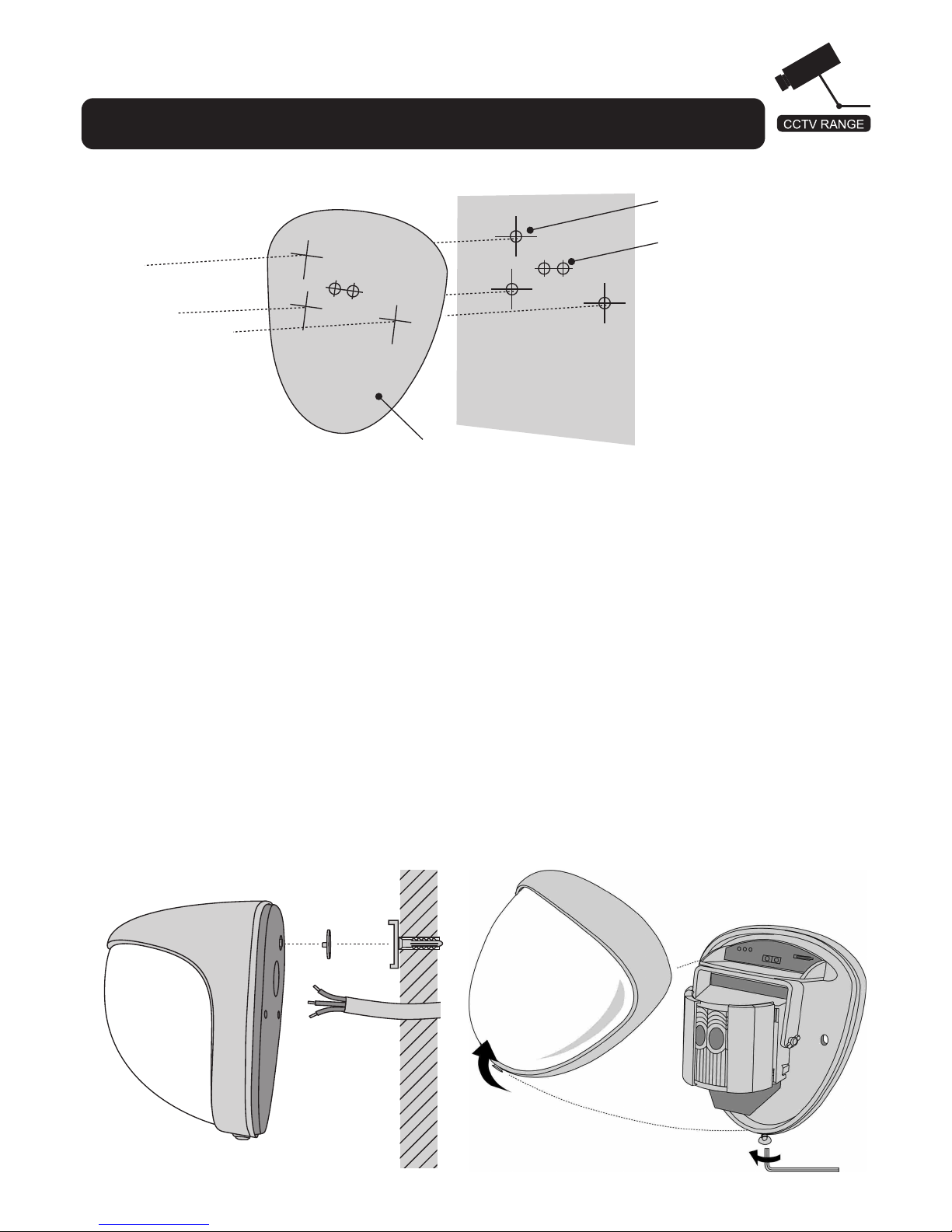
fig. 3
fig. 1
Optional for Tamper Cup
fig. 2
Cable Holes
3
T emplate
Installation & Set Up Guide
Stage 1 – Mounting the unit
- During installation the electronics must be protected against water, as trapped
moisture can affect or damage the unit.
1) Using the template provided drill the wall to accept the two fixing screws, the
cable entry and the tamper cup (if used).
See fig. 1 and 2.
Note: We recommend using the tamper cup on uneven wall surfaces.
2) Remove the cover assembly by loosening the locking screw using the allen key
provided. The cover hinges from the top and lifts out of the location slot.
See fig. 3.
Page 4
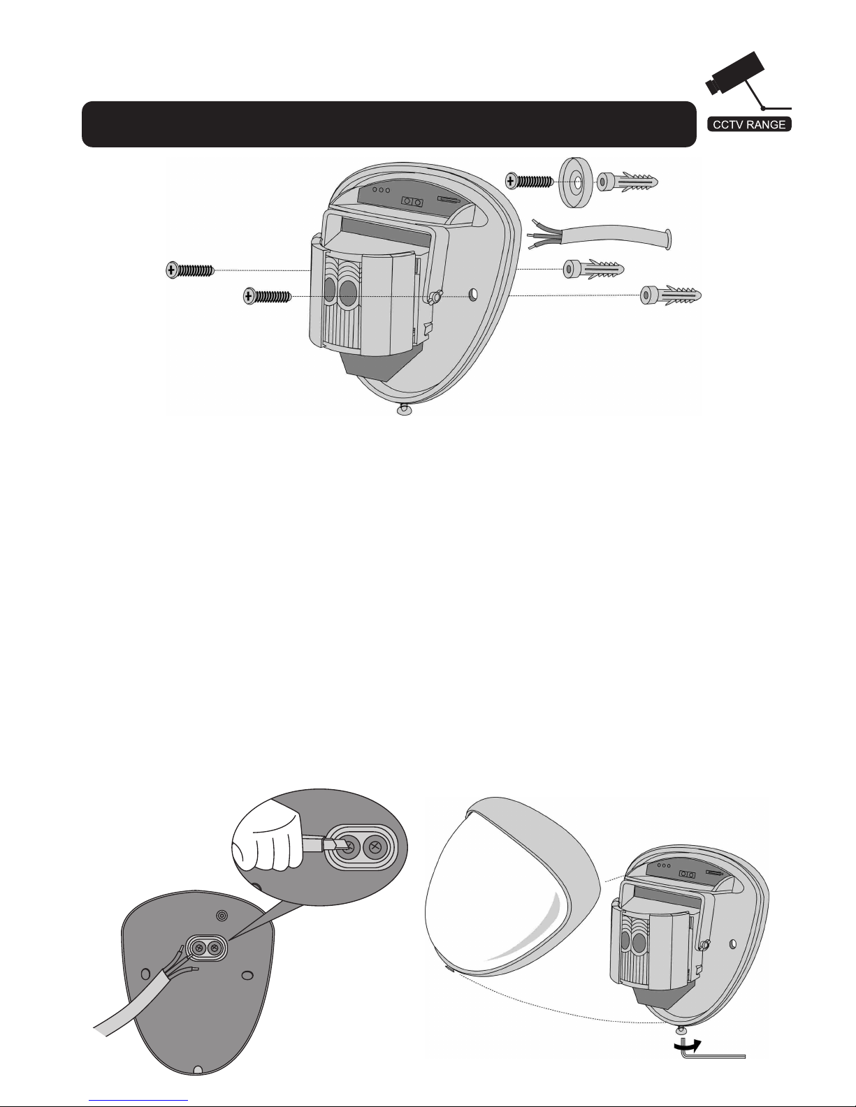
fig. 4
fig. 6
3) Feed standard 12 core alarm cable into the cable entry; bare the wires and
connect to the removable terminal block as shown in fig. 7. Screw the unit to the
wall ensuring that the tamper pin is correctly located and that the tamper microswitch
is closed. See fig. 4 and 5. To aid installation, two spare tamper feet are provided.
One is 1mm longer and the other is 2mm longer than the tamper foot originally
fitted. The tamper foot is a push fit and can be removed by carefully pulling it from
the pin. See fig. 2.
4) Always ensure when replacing the electronics module that the LED is facing
forward so as to ensure correct alignment of the beam pattern. (Refer section
titled "Beam Alignment")
5) When the detector has been aligned to suit the installation, replace the front cover
and lock as shown.
See fig. 6.
fig. 5
4
Installation & Set Up Guide
Stage 1 – Mounting the unit (Cont.)
Page 5

TAMPER CONNECTION
Installation & Set Up Guide
Stage 2 – Connecting the Unit
5
ALARM OUTPUT 1
TO GJD LIGHTING CONTROLLER
TO GJD LIGHTING CONTROLLER
MULTIPLEXER, PTZ DOME,
DVR, ETC.
MULTIPLEXER, PTZ DOME,
DVR, ETC.
NORMALLY CLOSED
TAMPER CIRCUIT FRONT + REAR
- A S +
12VDC SUPPLY
0V SUPPLY
ALARM OUTPUT 2
CCTV2
CCTV1
TAMPER CONNECTION
fig. 7
fig. 8
Stage 3 – Beam Alignment
- The GJD is supplied with two Fresnel lenses to provide a beam
pattern best suited to the cameras field of view. The 50 metre X 10 metre lens is
fitted to the unit when manufactured. If required this can be changed to the 50
metre X 5 metre lens which is supplied with the unit.
- Movement across the beams produces the best response and range, whilst
movement towards the detector will be less responsive. The unit detects the
changes in heat and movement in the beam pattern, therefore items such as trees,
shrubs, ponds, boiler flues and animals should be considered when positioning
the detector.
Page 6

Page 7

7
- The user can individually programme a number of configurable settings as
illustrated in the programming chart. Factory settings are shown as shaded boxes.
Changes to the existing settings can easily be made. To reset the factory settings
simply remove power form the detector, press and hold the programme button
(fig. 10) whilst temporarily applying power to the detector: either before installation,
with a PP3 battery, or by applying 12 Volts to the unit on site.
fig. 11
fig. 9
Installation & Set Up Guide
Stage3 – Beam Alignment (Cont.)
fig. 10
Blue LED
Programme Button
Stage 4 – Programming
Page 8

8
NOTE: When power is applied to the
the user has a time slot of 5 minutes to start using the
IR keyfob. The timer can be reset by either pushing the
program button as shown in fig.10 or by removing
and then reapplying power to the
RANGE MTRS
PULSE COUNT
LED
'S' OUTPUT LUX LEVEL
CONTACTS
TIMER SECONDS
PROGRAMMING CHART
CCTV 1
CCTV 2
25
1
OFF
2
2
30
2
ON
5
5
40
10
10
40
40
505024HR
60
N/O
N/O
N/C
N/O
N/C
N/C
PRESS 7 TIMES TO FLASH OUT YOUR SELECTED SETTINGS.
PRESS 8 TIMES TO RESET THE GJD FACTORY SETTINGS.
OPTIONS
AUX
45
20
20
50
30
30
1
2
3
4
5
6
1 2 3 4 5 6 7
8
SETTING
7
8
To change any of the settings: -
1) Press the programme button as shown in fig. 10 (or key fob button shown in fig.
11, 12) for the number of the Option to be changed i.e.once for range, twice for
pulse count, three times for LED, four times for Lux, five times for contacts & six
times for timer.
2) Wait four seconds until the blue LED indicator goes off.
3) The indicator will then flash out the existing setting.
4) To change the setting for that option, press the button the number of times
required for the new setting.
5) The indicator blinks twice and the changes are stored.
ON/OFF
Installation & Set Up Guide
Stage 4 – Programming (Cont.)
fig. 12
Page 9

9
Any alterations made to the settings are stored in the detector's
non volatile memory.
EXAMPLE
To change the LED Setting from OFF to ON.
1) Press the programme button three times and release the button.
2) Wait until the indicator goes off.
3) The indicator will now flash once.
4) Press the programme button twice and release the button.
5) The indicator flashes twice showing that the option has been stored and the
detector returns to normal operation.
Stage 5 – Walk Test
Installation & Set Up Guide
Stage 4 – Programming (Cont.)
- The range of the detector increases without the front protective cover. Therefore
the front cover must be fitted to establish the correct beam pattern alignment and
when testing the outputs. Use the programme table on page 8 to adjust the range
as necessary and pan and tilt the lens module over the field of view to obtain the
correct coverage area.
- When the 'program' button is pressed momentarily the blue indicator lights and
pulse count '1' is automatically selected. The unit can then be aligned. The blue
indicator will light on the
every time a detection takes place. This
test mode will automatically cancel five minutes after last detection. Alternatively,
remove the power and then re-apply.
- If automatic lighting is required to illuminate the area during recording, the
connects directly into any of the GJD lighting controllers for
simultaneous recording and automatic lighting at dusk. The signals from the
detector also provide an audible and visual indication of detection activity 24 hours
a day. As the GJD lighting controllers also have a pulse count option, this must
be set to '1' on the controller when using the
for event recording.
Page 10

Installation & Set Up Guide
Stage 6 – OPTION Definitions
10
PULSE COUNT
- This is the number of times the unit has to detect on both of its sensors before
signalling an output.
LED MONITOR
LED Off - LED disabled
LED On - LED signals a detection
LUX SETTING
- This is the approximate level that the ambient light must reach before the 'S'
output will become active when there is an activation.
The 'S' output switches negative for 60 seconds when there is a detection and
the light level is below the programmed setting.
The 'S' output is an open collector type rated at a maximum of 25 mA.
CCTV1 & CCTV2 OUTPUTS
- These are magnetically immune volt free relay contacts used to trigger alarm
inputs on connected equipment. They can be set to be both normally open, one
normally closed and one normally open or both normally closed.
TIMER
- The timer setting adjusts the time that the relays change state after activation.
The contacts are rated at a maximum of 24V AC/DC @ 50 mA.
ACCESSORIES
GJD is able to supply the following accessories to aid installations:
GJD303 Infra Red key fob programmer
GJD304 Conduit cable entry adaptor ring
GJD305 Pole mount clamp
Page 11

11
Installation & Set Up Guide
INSTALLATION NOTES
Page 12

07103
 Loading...