

DT Communications SafeKare CRU101A Quick Reference Booklet And User Manual

Quick Reference Booklet And User Guide
Version 1.4
SafeKare™ Model CRU101A
Version 1.4

SafeKare
TM
Alzheimer’s disease or different forms of Dementia can affect all who have to deal
with the care of individual family members stricken with this unfortunate condition.
A major problem in providing home care for patients, is knowing that the patient is
within the caregiving control area. All too often, for whatever reason, the patient
will leave the control area without the caregiver’s knowledge. This can be a
dangerous situation for the patient, as well as a frustrating problem for the
caregiver.
DT Communications Inc. has developed a simple method of alerting a busy
caregiver whenever the patient leaves a defined control area.
Our company has designed a unit that can be used both inside and outside the
home or caregiving facility. The unit will alert the caregiver if the patient leaves or
moves outside the range of
the SafeKare™ system.
DT COMM Inc. 2 Version 1.4

Congratulations on the purchase of your SafeKare™ Caregiver Assistant. This
information sheet will guide you through the Quick Start setup and operation of your
SafeKare™ system. Refer to your User’s Manual for details on setting up and
operating the caregiver system.
“DO NOT” power on the Caregiver Receiver CRU101A until the
WARNING
battery has been charged. See Section 5 of the user’s manual for
help if necessary.
Table of Contents
1 UNPACKING THE SYSTEM COMPONENTS.........................................................................4
1.1 CHARGING THE CAREGIVER RECEIVER......................................................................................5
1.2 UNPACKING THE BADGE/FOB ....................................................................................................5
1.3 FOB OPTION: ACTIVATING THE PATIENT FOB............................................................................ 6
1.4 BADGE OPTION: ACTIVATION OF THE PATIENT BADGE .............................................................7
1.5 SYSTEM LEARN MODE............................................................................................................... 7
2 USING THE SAFEKARE CAREGIVER SYSTEM...................................................................8
2.1 CHECKING THE SYSTEM RANGE ................................................................................................8
2.2 PLACING THE BADGE OR FOB UNIT ON THE PATIENT................................................................. 9
2.3 ENSURING CORRECT USAGE OF THE SAFEKARE™ SYSTEM .....................................................10
DT COMM Inc. 3 Version 1.4
1 Packing List
Before unpacking this caregiver kit, take out the packing list. As you unpack the kit, check off the
items listed on the packing list
Example packing list
Sent Received
Caregiver Receiver, CRU101A ___
X___ _______
Wall Power Module, WPU101A ___X___ _______
Hanging Patient Fob, FOB101A ___
Coin style Battery #CR2032 ___
X___ _______
X___ _______
Hanging Patient Badge, PB101A (Optional) _______ _______
Base Stand for Caregiver Unit, BS101A (Optional) _______ _______
Belt Clip For Receiver Unit BC101 (Optional) _______ _______
Charging Plug For Car/Vehicle CP101 (Optional) _______ _______
READY TO USE Option (Optional) _______ _______
1.1 Unpacking the System Components
Unpack the box containing your SafeKare™ system. Ensure that all items are present and
accounted for. Check your packing list to see what items were included in your system. The
packing list for a basic system is shown below.
If a part of the system you ordered is missing, consult the User’s Manual for instructions on
contacting the company.
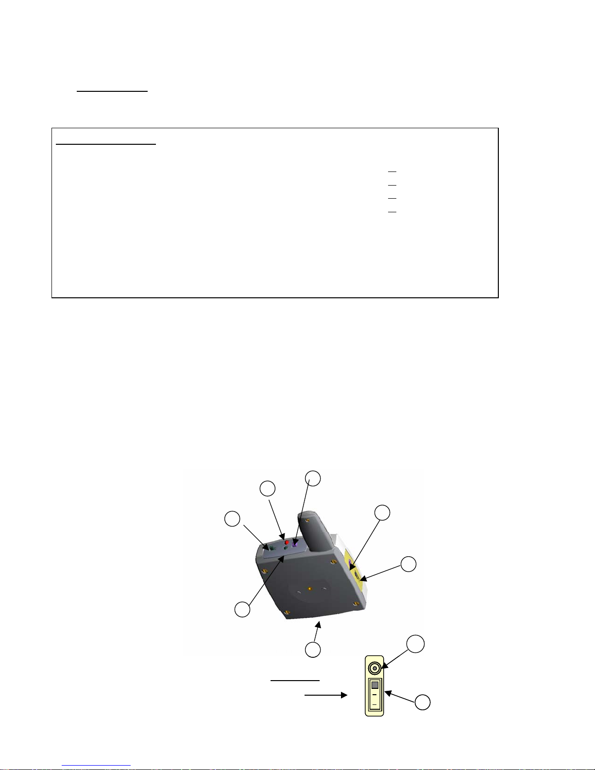
Figure 1. Location Of Receiver Functions
6
6
7
7
5
M
M
5
4
4
5
5
S
S
4
L
L
4
1
1
1 Power Switch
1 Power Switch
2 Low Ba ttery LED
2 Low Ba ttery LED
3 Base Stand DC Power Charging Connector
3 Base Stand DC Power Charging Connector
4 Range Switch
4 Range Switch
5 DC Power Charging Jack
5 DC Power Charging Jack
6 Alarm Reset Switch
6 Alarm Reset Switch
And Learn Mode Switch
And Learn Mode Switch
7 Red Alarm LED
7 Red Alarm LED
2
2
Range Switch
Range Switch
S – Short
S – Short
M- Medium
M- Medium
L- Long
L- Long
3
3
DT COMM Inc. 4 Version 1.4
Before your SafeKare system is used, the battery in the caregiver receiver must be
!
The locations of the switches, indicators, and power jack, for the CRU101A receiver, are
shown in Figure 1. Become familiar with each function location.
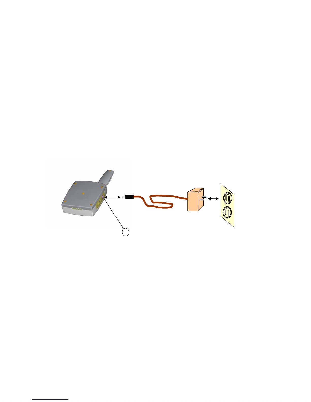
1.2 Charging the Caregiver Receiver
Plug the AC adapter into the wall, and then plug the other end into the caregiver receiver.
See Figure 2 for reference.
A full charge will be reached in approximately 6-8 hours. The unit will not be damaged if left
charging for longer than 8 hours.
After the caregiver receiver has been charged, the receiver is ready for use.
fully charged.
SK101A
SK101A
SK101A
Power Plug
Power Plug
Power Plug
WPM101
WPM101
WPM101
5
5
5
DC Power Jack
DC Power Jack
DC Power Jack
Figure 2. Charging the Battery
1.3 Unpacking the Badge/Fob
Remove the badge or fob from the metal case.
Do not dispose of this metal box. It may be needed to store or
.
!
ship the fob or badge
110/120 V
110/120 V
110/120 V
AC Outlet
AC Outlet
AC Outlet
DT COMM Inc. 5 Version 1.4
1.4 Fob Option: Activating the Patient Fob
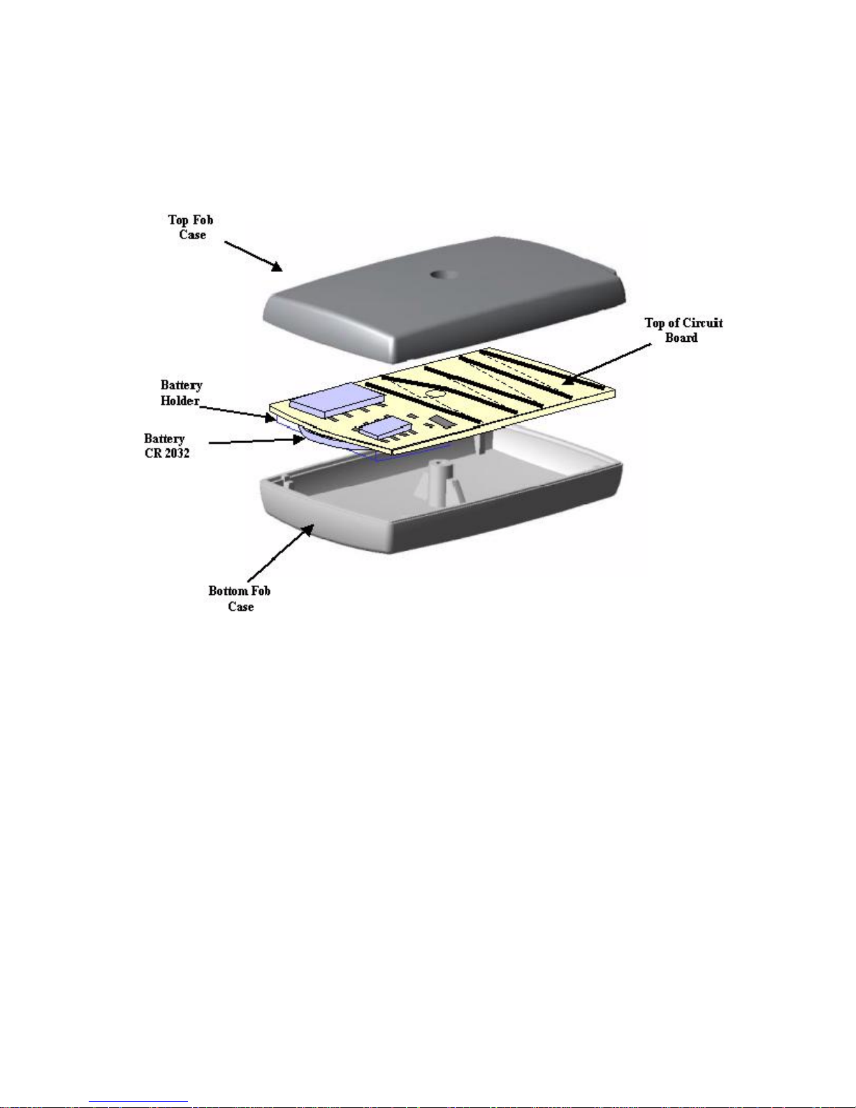
Place the patient fob FOB101A face down on a flat table like surface. Remove the screw
located in the center of the fob and remove the cover. See Figure 3.
Figure 3 Removing The Back of The Fob
The fob battery sits on the backside of the circuit board. Remove the battery from the
protective plastic pouch that came in your kit. Insert the battery as shown in Figure 4. Note,
the battery must be placed into the holder with the minus (-) side of the battery against the
circuit board. The plus (+) side of the battery faces away from the circuit board. Replace
the circuit board after the battery is installed. Replace the cover and screw the back
together. The fob is now ready to use.
DT COMM Inc. 6 Version 1.4

My
My
My
Battery
Battery
Minus (-)
Battery
Battery
Plus (+)
Slide Into Holder,
Slide Into Holder,
Minus Side
Toward Board
Toward Board
Battery
Battery
Holder
Holder
Figure 4. Inserting the Battery
Badge Option: Activation of the Patient Badge, OPTIONAL Equipment
1.5
The patient badge comes with a preinstalled
PB101A Pat ient Badge Tag
PB101A Pat ient Badge Tag
battery. The battery has not been factory
activated in order to preserve battery life. On
the backside of the badge, locate the circle
about ½ inches in diameter with the inscription
IF Found Please Contact
IF Found Please Contact
IF Found Please Contact
-
-
-
555 - 1000
555 - 1000
555 - 1000
1) 408
1) 408
1) 408
2) 408 - 555 - 6000
2) 408 - 555 - 6000
2) 408 - 555 - 6000
-
-
-
555 - 2000
555 - 2000
555 - 2000
3) 800
3) 800
3) 800
START located near the middle of the badge.
Start
Start
Hold the badge firmly with one hand and with
Start
the other hand use a finger to press the circle
Name Is
Name Is
firmly for 6 to 7 seconds. The badge should
now be active and ready for use
Name Is
Jean Doe
Jean Doe
Jean Doe
Figure 5, PB101A Hanging Badge
1.6 System Learn Mode
Before the caregiver receiver can operate with the patient badge or fob, it must first learn
the badge or fob ID code. Place the badge or fob 2 – 3 feet away from the caregiver
receiver. Refer to figure 6. Turn on the caregiver receiver (refer to figure 1). Wait for
receiver to initialize, indicated when the two LED’s stop flashing. Locate the “Reset-Learn”
button on the caregiver receiver. Hold caregiver receiver in the upright position and press
down on the ‘Reset/Learn” button switch. Hold the button down until an audible beep is
heard from the caregiver receiver. Within 3 to 15 seconds a second audible sound (a long
beep) should be heard. This indicates the receiver has learned the badge/fob code. If the
receiver starts to alarm, repeat the learn function. If the alarm condition continues, consult
the Trouble shooting section of the User’s Manual
DT COMM Inc. 7 Version 1.4
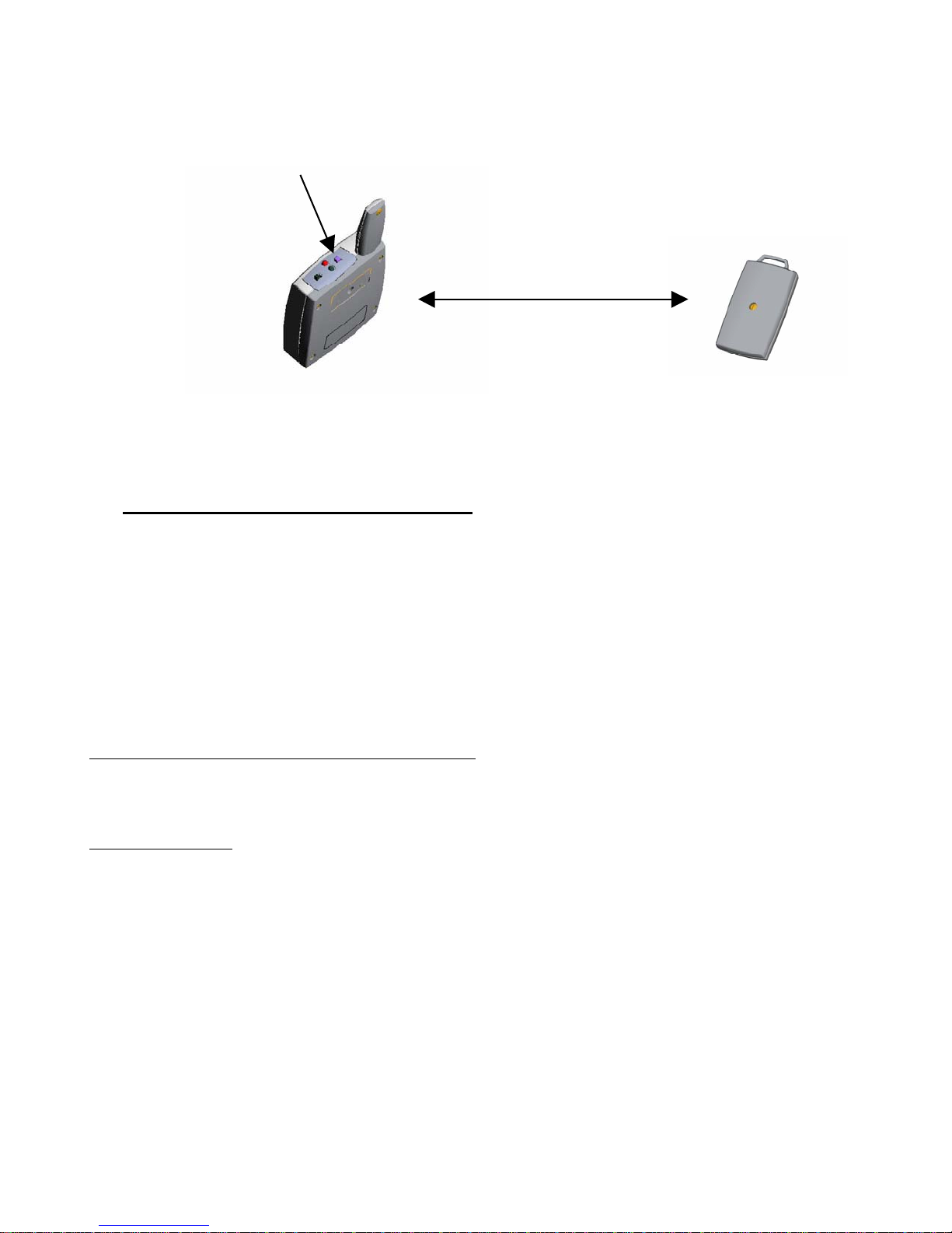
Press RS/Learn Switch, Hold Down Until “Beep”
Press RS/Learn Switch, Hold Down Until “Beep”
2 to 3 Foot
2 to 3 Foot
Separation
Separation
Figure 6. Setting Up Receiver Learn Mode
Using the SafeKare Caregiver System
2
A detailed description of using the CRU101A system is described in the User’s Manual. Refer
to the User’s Manual if you have any problems using the “Quick Start User Guide.” A short
system check of the receiver operating at different range settings is described in the next
section. For a detailed description see Section 6 of the User’s Manual. Note the locations
where the receiver starts to alarm as you move away from the badge or fob. This will be an
indication of how the unit will operate in your home environment.
2.1 Checking the System Range
Refer to Figure 1 for the following instructions. Turn the caregiver receiver on, and place the
badge or fob unit on a table or similar object. Set the switch located on the side of the
receiver to the “S” position (short range setting).
Walk very slowly away from the badge or fob and record the distance at which the caregiver
receiver begins to alarm (a short beep, followed by a continuous beep 12 seconds after the
short beep).
Switch the receiver to the “M” position (medium range setting). The beeping should stop
within 12 to 15 seconds. Continue moving
the distance at which the caregiver receiver begins to alarm (a short beep).
Switch the receiver range to the “L” position (long range setting). The beeping should stop
in about 12 to 15 seconds. Continue walking
distance at which the receiver alarms, a short “beep” followed by a “continuous beeping”
after 12 seconds. The receiver is now in full alarm mode.
slowly
away from the badge or fob. Again, record
slowly
away from the fob. Again, record the
DT COMM Inc. 8 Version 1.4
 Loading...