

DTC Communications TAC2001 User Manual

DOCUMENT NUMBER: OP1920104 REV. B
DESCRIPTION: TACTICAL REPEATER TAC-COM 2001
OPERATING INSTRUCTIONS
ECO NUMBER:_______
Page____of________
Date:_____________
SIGN OFF DATE: mm/dd/yy
Proj Eng._________________
Mfg Mgr. _________________
Documentation ____________
Eng. Mgr._________________
Purchasing _______________
Orig:_____________
Op1920104 REV B 04/09/01 Page 1 of 7
OPERATING INSTRUCTIONS
TAC-COM 2001
TACTICAL REPEATER
OP1920104 REV B
DTC COMMUNICATIONS, INC.
75 Northeastern Blvd.
Nashua, NH 03062
Tel: (603) 880-4411
Fax: (603) 880-6965
Op1920104 REV B 04/09/01 Page 2 of 7
Description:
Repeaters are devices, comprised of both a receiver and transmitter, which are used
to extend the range of a transmitter. It does this by receiving a weak signal on one channel
and re-transmitting the signal (at the same time) on a 2
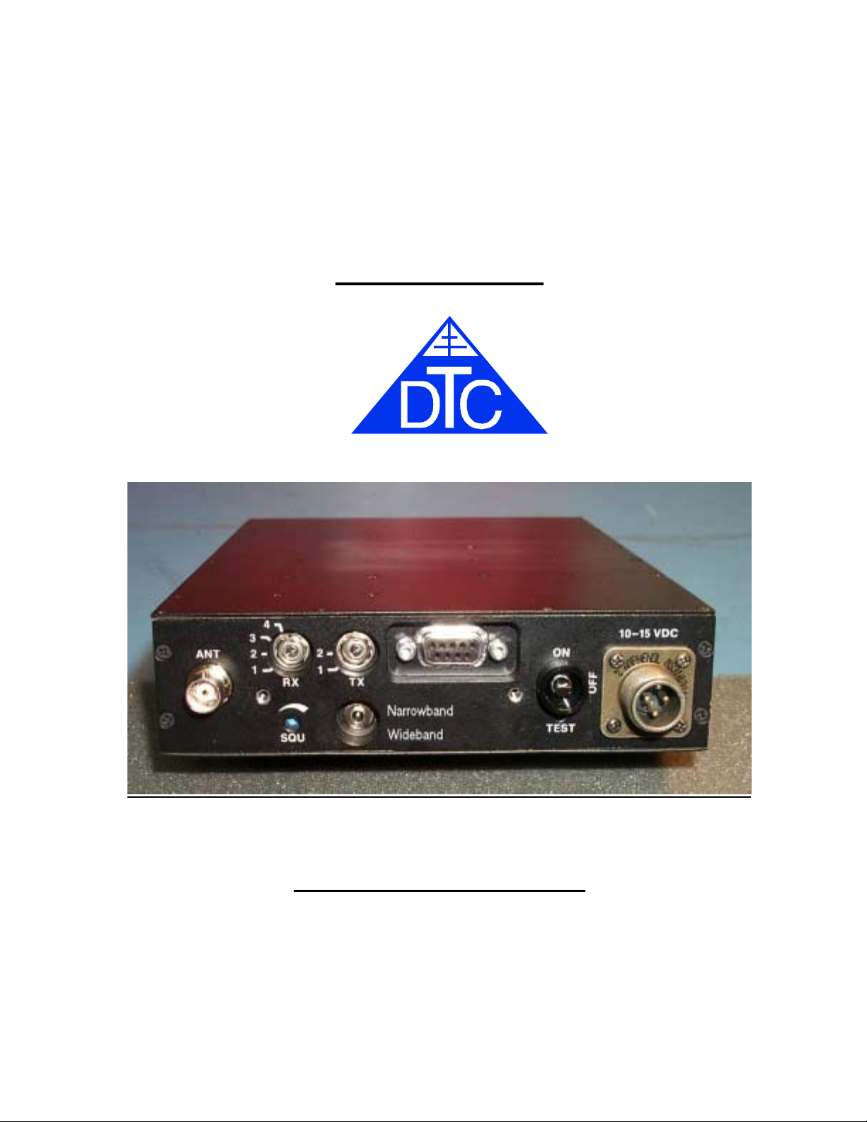
The TAC/COM-2001 is a portable 1.7 Watt VHF FM tactical repeater capable of receiving
both 12.5 kHz (NTIA compliant) and standard wideband (25.0 kHz) signals and rebroadcasting them as 12.5 kHz signals. The TAC/COM repeater is housed in a sealed,
water resistant, milled aluminum housing and is designed to operate over a wide
temperature and humidity range. Both transmitter and receiver sections are frequency
synthesized; and both are locked to highly stable temperature compensated crystal
oscillators (TCXO’s). The repeater will transmit continuously for over 10 hours on one
battery pack (9 D cells). Special attention has been paid to protecting the switch settings by
the use of a control section door.
Operation:
transmitter such as a pager disguise. The repeater should remain in standby (not
transmitting) until the transmitter is activated. When the transmitter is on and in range of
the repeater, the repeater will re-transmit the signal on another selected channel. Typically,
the repeater is powered from its own D-Cell battery box, or via another DC source such as
automotive power. The antenna is very important. The performance of the TAC/COM is
highly dependent on the proper location and orientation of the antenna.
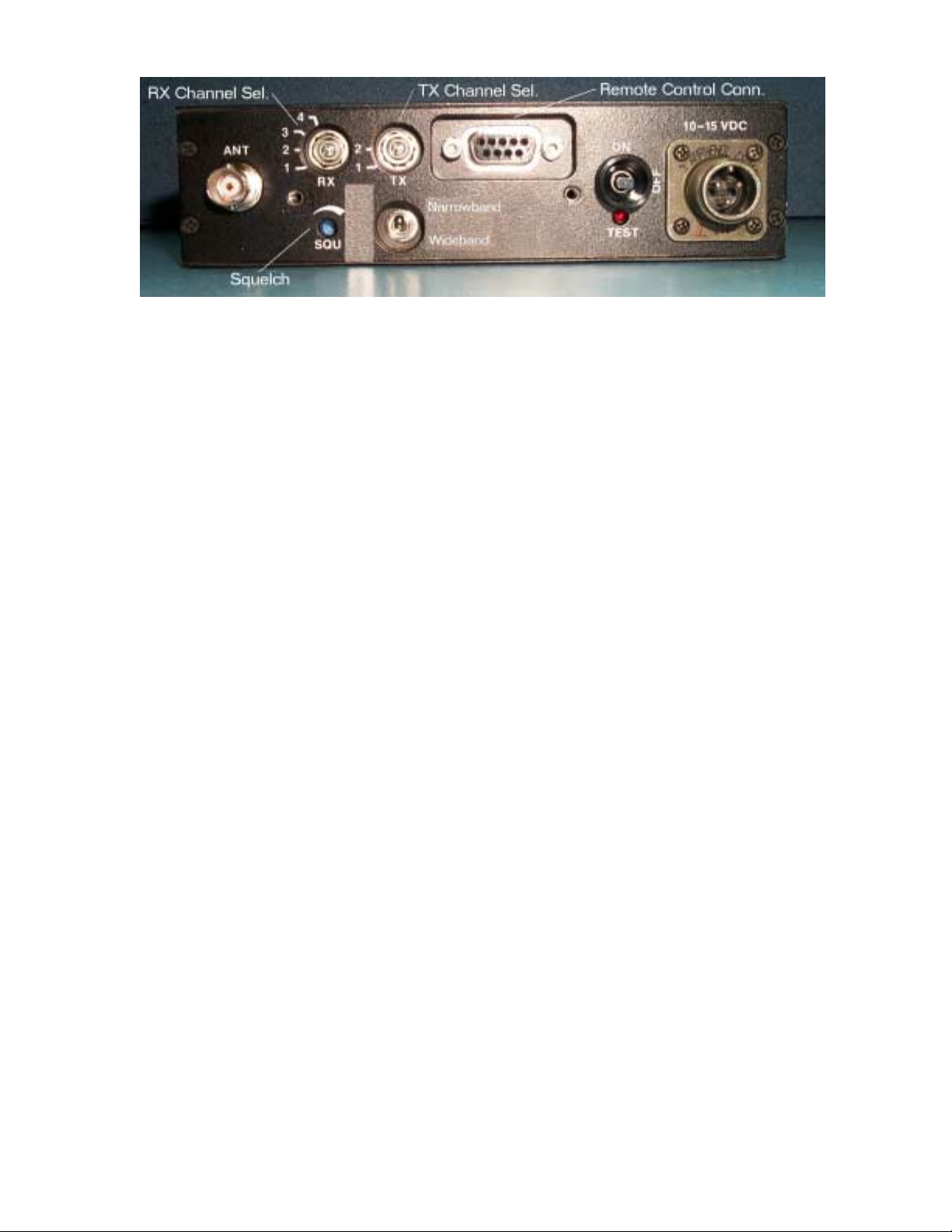
To set up the TAC/COM 2001 repeater, remove the control door by turning the
thumbscrews CCW. First set the bandwidth switch. Is the transmitter that you are using
narrowband (12.5 kHz) or is it an older wideband (25 kHz) unit? It is always best to select
the bandwidth, which matches the transmitter. If unknown, the repeater can receive either
signal in the WB mode, so this is a good default. Note: using a narrowband transmitter with
a wideband receive setting will cause some loss of audio.
The repeater’s receiver channel is next set to the transmitters (bodywire) frequency using
the RX channel control. The repeaters output channel also needs to be set to a channel
covered by the listening post receiver. This is accomplished with the TX channel control.
The squelch control is factory set and normally does not require adjustment.
CAUTION: DO NOT TIGHTEN (TURN CW) THE SQUELCH CONTROL
UNLESS YOU ARE EXPERIENCING A CONSTANT TRANSMIT CONDITION –
The typical mission of the repeater is to extend the range of a low power FM
nd
channel, usually at higher power.
 Loading...