

DTC Communications PDTX250S User Manual
COFDM Transmitter
Model Pd-TX-100 100 mW Output
Model Pd-TX-250 250 mW Output
DTC COMMUNICATIONS, INCORPORATED

how to contact DTC
For operator and troubleshooting information,
customers are encouraged to refer to the
details in this manual. For additional
clarification or instruction, or to order parts,
contact DTC.
Customer Service is available Monday through
Friday between the hours of 9:00 AM and
5:00 PM EST at:
Tel: 603-880-4411
Fax: 603-880-6965
Website: www.dtccom.com
Email: info@dtccom.com
486 Amherst Street
Nashua, New Hampshire 03063
copyright notice
Copyright © 2005
DTC Communications, Inc. All rights
reserved. No part of this document may be
reproduced, transmitted, transcribed, stored
in a retrieval system or translated into any
language or computer language, in any form
or by any means, including but not limited to
electronic, magnetic, mechanical, optical,
chemical, manual or otherwise, without the
prior written permission of DTC
Communications, Inc.
disclaimer
The information in the document is subject to
change without notice. DTC makes no
representations or warranties with respect to
the contents hereof, and specifically disclaims
any implied warranties of merchantability or
fitness for a particular purpose. DTC reserves
the right to revise this publication and to
make changes from time to time in the
content hereof without obligation of DTC to
notify any person of such revision or changes.
trademarks
Trademarks of DTC Communications, Inc.
include:
• DTC
• MiniPIX
• DynaPIX
Other product names used in this manual are
the properties of their respective owners.
®
®
warranty
DTC warrants its manufactured components
against defects in material and workmanship
for a period of two (2) years, commencing on
the date of original purchase.
Products manufactured by others that are
approved for use with DTC equipment are
warranted for the manufacturer’s warranty
period, commencing from the date of shipment
from DTC.
FCC information
The following information is provided as a
service to our law enforcement customers who
require a Part 90 station license for video
surveillance operations.
You will need to provide two documents:
• Form 600 (the application form)
• Form 159 (the filing fee form)
Forms can be obtained from the FCC on their
website at:
www.fcc.gov
You can also contact the FCC using their FAX
back service at: (888) 418-3676
Additional instructions are available by
telephone at: (888) 225-5322
The filing fee form is returned to:
Federal Communications Commission
1270 Fairfield Road
Gettysburg, PA 17325-7245
2
DTC COMMUNICATIONS, INC.
PN OP1920303 REV 2

manual conventions
NOTE: Describes special issues you should
be aware of while using a particular function.
WARNING: Calls out situations in which
equipment could be damaged or a process
could be incorrectly implemented, but in
which operator safety is not a factor.
TIP: Describes application hints.
RF EXPOSURE STATEMENT
A separation distance of at least 20 cm must be
maintained between the antenna and the body of
the user or nearby persons.
NOTE: This device is for occupational use
only. Occupational users are those persons
who are exposed as a consequence of their
employment, provided these persons are fully
aware of and exercise control over their
exposure.
TABLE OF CONTENTS
Quick Start ............................................................................ 4-5
Complete These Steps ................................................................ 4
Thermal Issues ........................................................................... 4
Introduction ............................................................................... 6
Operation ............................................................................... 7
Using your Palladium Transmitter ................................................ 7
Changing your Transmitter Configuration .................................... 7
Components ........................................................................... 8-9
Programming ...................................................................... 10-15
System PC Controller Application Software .............................. 10
Transmitter Control Application ................................................. 11
Specifications ..................................................................... 16-17
Warranty ............................................................................. 18
Contact Us ............................................................................. 19
DTC COMMUNICATIONS, INC.
3
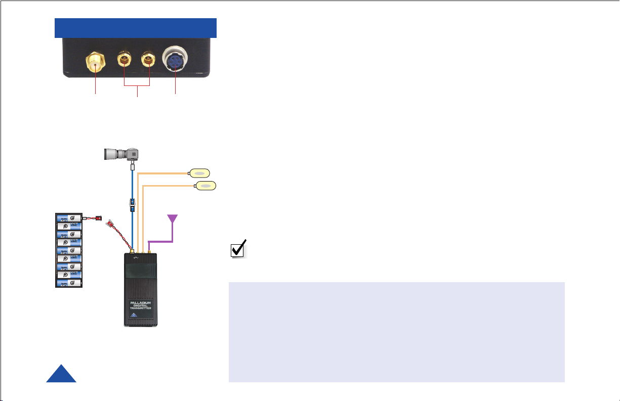
QUICK START
12
Palladium Transmitter, Top View
CAMERA
3
MICROPHONE(S)
ANTENNA
Complete these steps:
1 Connect the transmitter antenna to the SMA connector on the top of the
Palladium unit.
2 If you plan to use audio, connect one or two microphones to the Audio 1
and/or Audio 2 LEMO connectors.
3 Connect power and video input via the Multi I/O cable to the 6-pin
Hirose connector:
a Attach your camera video input (75 ohm composite video source in
PAL or NTSC) to the Multi I/O cable BNC connector.
b Apply the necessary power to your camera and turn ON.
c Attach a 12 VDC power source (such as the supplied battery pack or
the AC power adapter) to the Multi I/O cable via the Molex connector.
The input voltage range is from 10 to 18 VDC.
NOTE: Eight Channel LEDs are located under the sliding control
panel door. If all 8 green LEDs are flashing, this indicates that your
battery source is low.
9 AA
BATTERY
PACK
Typical Wiring Configuration
4
DTC COMMUNICATIONS, INC.
Thermal Issues
Higher power Palladium Pd-TX-250 Transmitters feature
mounting tabs for convenient mounting and heat
dissipation. If your Palladium Transmitter has these tabs,
proper heat sink mounting is recommended for optimal
performance. An optional heat sink can be purchased
from DTC. See page 8 for heat sinking instructions.
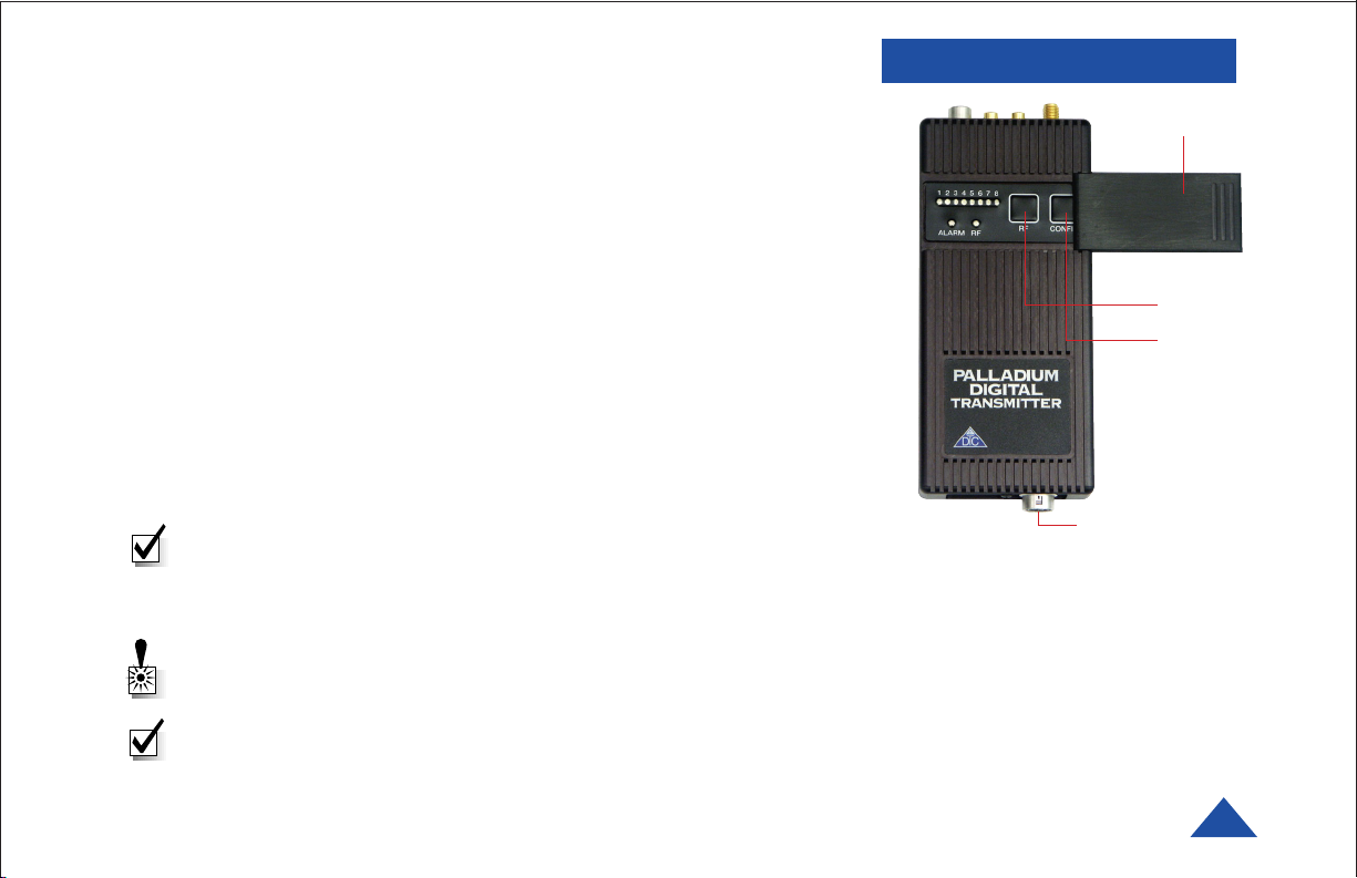
QUICK START
4 Slide the control panel door open (to the right).
5 When power is applied, the transmitter will power-up to its last state.
Ensure that the green RF LED turns ON indicating the unit is
transmitting. If needed, push the RF button to begin transmitting.
The channel number LED also turns ON, representing the most recent
channel setting from the last time the transmitter was used.
6 If you need to change the operating channel, press the CONFIG button
to cycle through the 8 available channels indicated by the channel
number LEDs. Refer to the Programming section on page 10 for more
information on channel settings. When you change the channel
configuration, the RF transmission is automatically switched OFF to
prevent accidental interference. When you have selected the channel
you need, push the RF button to start transmitting again. The RF LED
will turn ON.
NOTE: A red ALARM LED indicates that no video is connected.
Your Transmitter is now operational. Confirm its signal with your
Palladium Receiver.
WARNING: Do not apply power to the transmitter unless an antenna
or non-radiating load is connected to the Antenna SMA connector.
NOTE: The RF switch should remain ON during normal use. The RF
automatically shuts off during programming to prevent accidental
transmissions on unintended frequencies.
4
5
6
Optional Data and
Chaining Connector
Palladium Pd-TX-100 Transmitter,
Front View
DTC COMMUNICATIONS, INC.
5

INTRODUCTION
Palladium Pd-TX-100
100-Milliwatt Digital Transmitter
The Palladium Series of digital video transmitters provide exceptional video
quality in high multipath environments. They are ideal for use inside
buildings, in urban areas, and in other applications where multipath
would normally cause video tearing or breakup.
All Palladium Series transmitters are designed for spectrum-efficient 2.5
MHz channel spacing. Approximately 400 carriers are used to transmit
video and two channels of voice and data. Palladium transmitters may be
located on adjacent channels without a guard band. AES 128-bit
encryption ensures users of secure communications.
The Palladium 100 is a small transmitter with a 100 mW RF power output.
This unit is ideal for concealments and shorter range robotic and UAV
applications. The package is only 7.5” x 2.5” x 0.75”. Power consumption is
6 Watts. All connections are conveniently located off the ends of the unit.
Many users will want to power this device with disposable batteries.
The Palladium 250 incorporates an internal power amplifier bringing total
power output to 250 mW. Height and width are identical to the Palladium
100, with the depth of the unit increasing an additional 0.5”. The
Palladium 250 is ideal for many surveillance applications and short to
mid-range robotic and UAV applications.
Both versions are built out of rugged milled aluminum housings. The
Palladium 250 features mounting tabs for convenient heatsinking (page 8).
6
DTC COMMUNICATIONS, INC.
NOTE: Use only Lithium batteries with this device.
 Loading...