

DTC Communications PDTX100SBW User Manual
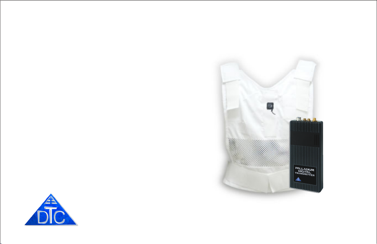
VidiVest Palladium
body worn
video vest system
with PalladiumTM Digital Technology
TM
DTC COMMUNICATIONS, INCORPORATED

how to contact DTC
For operator and troubleshooting information,
customers are encouraged to refer to the
details in this manual. For additional
clarification or instruction, or to order parts,
contact DTC.
Customer Service is available Monday through
Friday between the hours of 9:00 AM and
5:00 PM EST at:
Tel: 603-880-4411
Fax: 603-880-6965
Website: www.dtccom.com
Email: info@dtccom.com
486 Amherst Street
Nashua, New Hampshire 03063
2
DTC COMMUNICATIONS, INC.
copyright notice
Copyright © 2005, 2006
DTC Communications, Inc. All rights
reserved. No part of this document may be
reproduced, transmitted, transcribed, stored
in a retrieval system or translated into any
language or computer language, in any form
or by any means, including but not limited to
electronic, magnetic, mechanical, optical,
chemical, manual or otherwise, without the
prior written permission of DTC
Communications, Inc.
disclaimer
The information in the document is subject to
change without notice. DTC makes no
representations or warranties with respect to
the contents hereof, and specifically disclaims
any implied warranties of merchantability or
fitness for a particular purpose. DTC reserves
the right to revise this publication and to
make changes from time to time in the
content hereof without obligation of DTC to
notify any person of such revision or changes.
trademarks
Trademarks of DTC Communications, Inc.
include:
TM
• DTC
• Palladium
• ArmorNet
• SplitPIX
• MiniPIX
• DynaView
Other product names used in this manual are
the properties of their respective owners.
TM
TM
TM
TM
TM
warranty
DTC warrants its manufactured components
against defects in material and workmanship
for a period of two (2) years, commencing on
the date of original purchase.
Products manufactured by others that are
approved for use with DTC equipment are
warranted for the manufacturer’s warranty
period, commencing from the date of shipment
from DTC.
PN OP1920405 REV 1

manual conventions
TABLE OF CONTENTS
NOTE: Describes special issues you should
be aware of while using a particular function.
WARNING: Calls out situations in which
equipment could be damaged or a process
could be incorrectly implemented, but in
which operator safety is not a factor.
TIP: Describes application hints.
RF EXPOSURE STATEMENT
The Vidivest Palladium has been tested to meet
Occupational/Controlled exposure limits for Bodyworn
Devices per FCC rules under Chapter 47, Part 2,
Section 1093, paragraphs (b), (c), (d)(1), (d)(3) - Laboratory
Technique, and (d)(4), by a certified testing laboratory.
Information is available upon request.
NOTE: This device is for occupational use
only. Occupational users are those persons
who are exposed as a consequence of their
employment, provided these persons are fully
aware of and exercise control over their
exposure.
Quick Start ............................................................................ 4-5
Overview ............................................................................... 6
Components .......................................................................... 7- 9
Programming ...................................................................... 10-15
Specifications ..................................................................... 16-17
Warranty ............................................................................. 18
Contact DTC ............................................................................ 19
DTC COMMUNICATIONS, INC.
3
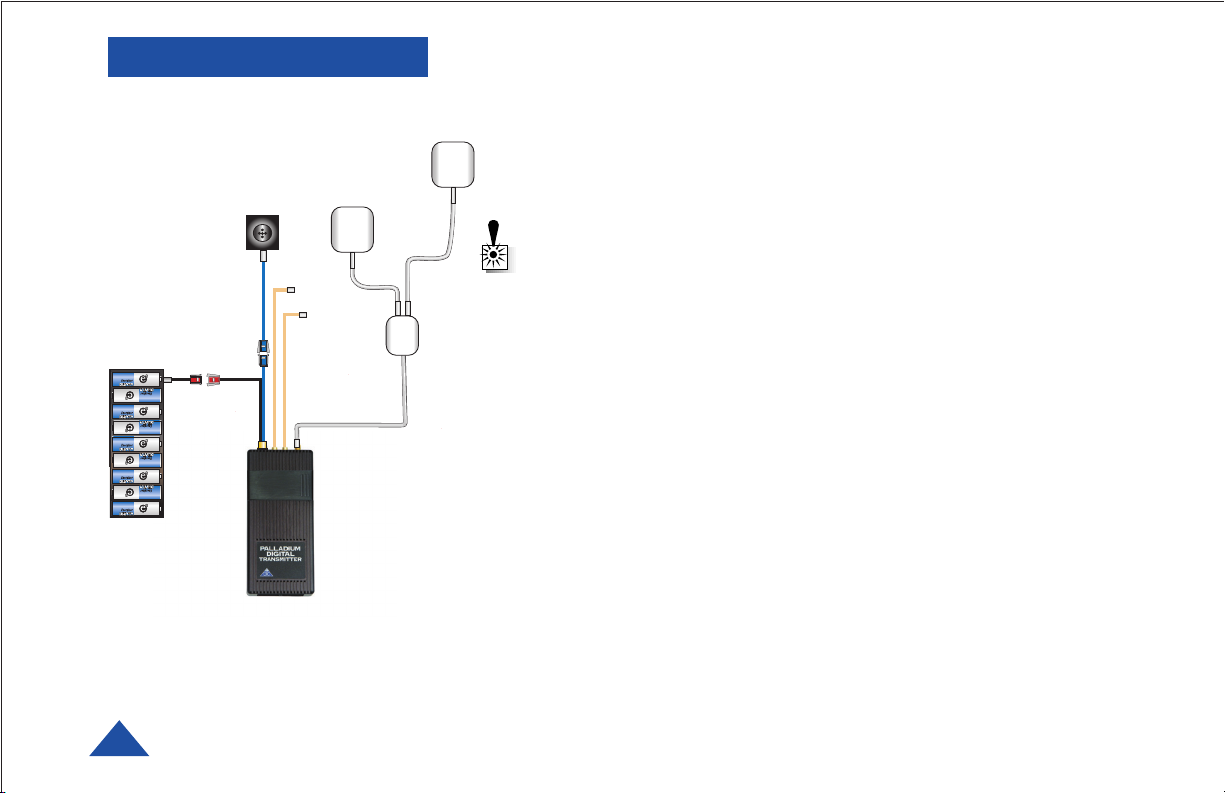
QUICK START
BUTTON
CAMERA
9 AA
BATTERY
PACK
VidiVest Palladium Wiring Diagram
4
DTC COMMUNICATIONS, INC.
REAR PATCH
ANTENNA
AUDIO
INPUT(S)
VidiVest Palladium
The vest is shipped with all components installed and ready for
FRONT PATCH
ANTENNA
SPLITTER
2. Remove the battery holder by carefully releasing the locking connector.
3. Install 9 NEW Lithium AA size batteries, observing proper polarity and
4. The transmitter has been factory programmed to eight preset channels.
use. Be careful with the button camera when working on the rear
pockets where most of the components are located. Setup the vest
on a clean, soft cloth on a tabletop for best results.
1. Inspect the bottom rear pocket section of the vest. Make sure
all connectors are secure as shown in the illustration (left).
Connectors are keyed and color-coded.
WARNING: Do not apply power to the transmitter unless an
antenna or non-radiating load is connected to the Antenna
SMA connector.
Connections
• Camera to Transmitter: 3-Pin to 3-Pin
• Audio (if used): Two Lemo connectors (Push/Pull locking)
• Power (Battery pack to TX): 2-Pin to 2-Pin
• Antenna: SMA Male to TX SMA Connector
Each section of the battery holder has a cover, which must be removed
with a Phillips screwdriver to allow the batteries to be inserted or
changed.
replace the screws for each section.
Make sure the channel frequency selected matches the receiver’s
frequency. Slide the control panel door open (to the right). If you need
to change the operating channel, press the CONFIG button to cycle
through the 8 available channels indicated by the channel number
LEDs. Refer to the Programming section on page 10 for more
information on channel settings. When you change the channel
configuration, the RF transmission is automatically switched OFF to
prevent accidental interference.
When you have selected the channel you need, push the RF button to
start transmitting again. The RF LED will turn ON. The transmitter
RF should always be set to ON. The vest is deactivated by
disconnecting power.
NOTE: The RF switch should remain ON during normal use. The RF
automatically shuts off during programming to prevent accidental
transmissions on unintended frequencies. DO NOT HOLD THE RF
BUTTON DOWN FOR MORE THAN ONE SECOND, or the unit will go
into sleep mode. In sleep mode, the unit is non-functional. If
necessary, recover from sleep mode by pressing and holding the RF
button for more than two seconds.
5. When power is applied, the transmitter will power-up to its last RF
ON/OFF state. Ensure that the green RF LED turns ON indicating the
unit is transmitting. If needed, push the RF button to begin
transmitting.
The channel number LED also turns ON, representing the most recent
channel setting from the last time the transmitter was used.
6. Put the vest on (refer to photos page 6). Tighten the Velcro side straps so
that the system components are held closely to the body. The rear flap
of the vest should be hanging loose.
7. Orient the camera on the Velcro for a proper (right side up) picture.
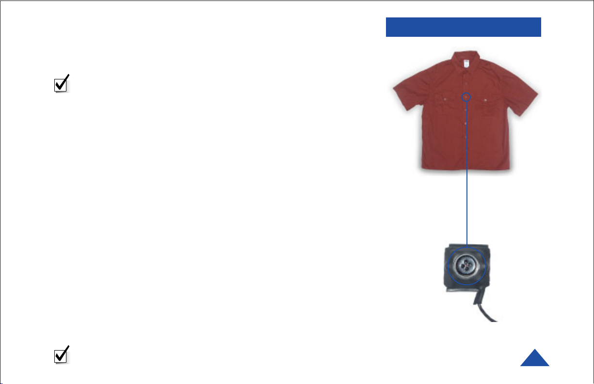
8. Put the shirt on over the vest. Button the camera through the
appropriate buttonhole in the shirt. (See photos right.)
9. Test the system. Verify the camera is properly positioned by looking at
the receiver’s monitor. Walk quickly for a few steps, returning to the
monitor. Make sure the camera’s field of view has not changed.
Reposition if necessary. Double-check the camera picture and angle
before the mission.
Your Transmitter is now operational. Confirm its signal with your
Palladium Receiver.
NOTE: The red ALARM LED typically indicates no video input.
It could also indicate a hardware failure or low battery power.
QUICK START
Casual Shirt
Button Camera
The camera position can be adjusted to
desired button hole.
DTC COMMUNICATIONS, INC.
5
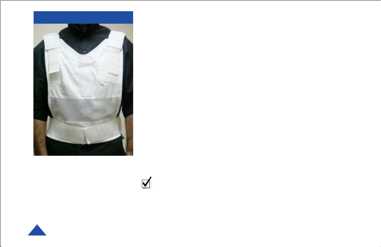
OVERVIEW
The VidiVest Fits Snugly On The Body
Using Velcro Fasteners.
One size fits all.
The Palladium VidiVest Vest is a covert, body worn, 100 mW COFDM
microwave video transmission garment system. Palladium digital
technology and our advanced antenna system combine to provide high
signal quality and very effective mobility. The vest conceals all
components and provides sheilding from transmitter heat. Power is
supplied by a concealed 9 AA battery pack.
The lightweight vest is designed to fit many body sizes and is ventilated for
comfort. It is designed to hold all system components as an undergarment
for use with a casual shirt. The design holds all components close to the
body, allowing a loosely fitting shirt to be buttoned over it without
protrusions or wires showing. A hard-wired ON/OFF switch is available as
an option. An optional wireless keyfob ON/OFF switch is also available.
The high-resolution color CCD camera is disguised as a shirt button.
The Palladium transmitter offers integral AES encryption. Two audio
inputs are provided.
Deployment is quick and easy. All connectors are color-coded and locking.
A special two-patch antenna harness, built into the vest, provides an omnidirectional transmission pattern. The entire vest system is powered from a
single battery pack, which holds 9 AA size Lithium batteries. A set of
NON-rechargeable Lithium cells have been provided in the kit. Battery life
with one set of fresh Lithium cells is more than 3 hours.
Note: Only Lithium Ion AA batteries are recommended.
6
DTC COMMUNICATIONS, INC.
 Loading...