

DTC Communications PD2TX100C User Manual
Palladium II Digital
TELEMETRY
CHANNEL
Palladium II
VIDEO TX
Audio
TELEMETRY
CHANNEL
Palladium II
VIDEO TX
Audio
COFDM Transmitter
Model Pd2-TX-100 100 mW Output
The most important thing we build is trust

how to contact COBHAM
For operator and troubleshooting
information, customers are encouraged
to refer to the details in this manual. For
additional
clarification or instruction, or to order parts,
contact COBHAM.
Customer Service is available Monday
through Friday between the hours of 9:00
AM and
5:00 PM EST at:
Tel: 603-880-4411
Fax: 603-880-6965
Website: www.cobham.com/dtc
Email: dtc.info@cobham.com
DTC Communications
dba Cobham Surveillance
486 Amherst Street
Nashua, New Hampshire 03063
copyright notice
Copyright © 2005 - 2010
COBHAM All rights reserved. No part of this
document may be reproduced, transmitted,
transcribed, stored in a retrieval system or
translated into any language or computer
language, in any form or by any means, including
but not limited to electronic, magnetic,
mechanical, optical, chemical, manual or
otherwise, without the prior written permission of
COBHAM.
disclaimer
The information in the document is subject
to change without notice. COBHAM
makes no representations or warranties
with respect to the contents hereof, and
specifically disclaims any implied warranties
of merchantability or fitness for a particular
purpose. COBHAM reserves the right to
revise this publication and to make changes
from time to time in the content hereof
without obligation of COBHAM to notify any
person of such revision or changes.
2
PN OP1920492 REV. E
manual conventions
NOTE: Describes special issues you should be aware of
while using a particular function.
WARNING: Calls out situations in which
equipment could be damaged or a process could be
incorrectly implemented, but in which operator safety is
not a factor.
TIP: Describes application hints.
RF EXPOSURE STATEMENT
FOR BODY-WORN APPLICATIONS, only the S-Band unit, DTC Part#
PD2-TX-100-S, has been FCC-approved (FCC ID H25PD2TX100S), AND
only when used in conjunction with DTC’s Palladium Digital VidiVest DTC
Part# Pd-VidiVest-S(-RC), or Digital Video Jacket DTC Part# Pd-VIDI-DJS(-RC).
FOR
ANY
ABOVE, a separation distance of at least 20 cm MUST be maintained
between the antenna and the body of the user or nearby persons.
When the unit is used consistent with the two previous notices, it
complies with FCC radiation exposure limits set forth for an uncontrolled
environment, per FCC Rules & Regulations, sections 1.1307, 2.1091 &
2.1093, as required by section 90.1217.
CONFIGURATION OTHER THAN THAT DESCRIBED
NOTE: Unless specifically designed for body-worn ap-
plications, the antenna must be kept at least 20 cm away
from the body of the user.
TABLE OF CONTENTS
Quick Start ..................................................................................................................4-5
Accessories ........................................................................................................................ 5
Introduction ......................................................................................................................6
Operation ........................................................................................................................ 7
Using your Palladium II Transmitter ........................................................................... 7
Changing your Transmitter Configuration ............................................................... 7
Components 8-9
Programming ..........................................................................................................10-17
System PC Controller Application Software .........................................................10
Transmitter Control Application .................................................................................11
Specifications ......................................................................................................... 18-19
Notes ........................................................................................................... 20-21
Warranty ...................................................................................................................22
Contact Us ...................................................................................................................23
NOTE: Do not allow the device to directly contact the
skin due to warm operating temperatures.
3
TELEMETRY
CHANNEL
Palladium II
VIDEO TX
Typical Palladium II Configuration
Antenna
Audio
Camera
Battery Pack
Power Option
QUICK START
A1
R/M
A2
L
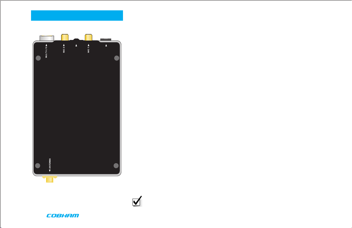
2
Palladium Transmitter, Top View
3
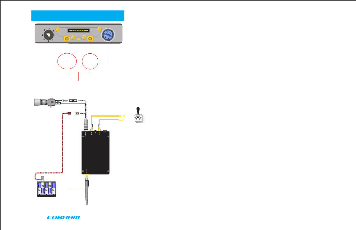
Complete these steps:
1 Connect the transmitter antenna to the SMA connector on the bottom of the Palladium unit.
2 If you plan to use audio, connect one or two microphones to the Audio 1 and/or Audio 2
LEMO connectors. If using monaural, use Audio 1.
3 Connect power and video input via the Multi I/O cable to the 6-pin Hirose connector:
a Attach your camera video input (75 ohm composite video source in
PAL or NTSC) to the Multi I/O cable BNC connector.
b Apply the necessary power to your camera (use supplied cable or
external source) and turn ON.
c Attach a 12 VDC power source (such as the supplied battery pack or
the AC power adapter) to the Multi I/O cable via the Molex connector.
The input voltage range is from 10 to 16 VDC.
WARNING: Do not apply power to the transmitter unless an antenna or non-radiating
load is connected to the Antenna SMA connector.
1
Typical Wiring Configuration
4

4 Set to the required configuration as indicated by the channel numbers. Refer to the
TELEMETRY
CHANNEL
Palladium II
VIDEO TX
Audio
Programming section on page 10 for more information on channel settings. Your Transmitter
is now operational. Confirm its signal with your Palladium Receiver.
QUICK START
4
Accessories
• 10 cell AA Battery Pack
• 12 VDC 2.5A Power Supply & AC Line Cord
• Microphone, Body-Worn, (2)
• Power & Video Cable
• Camera Power Cable (2.1 mm plug)
• DC Power Cable, flying lead
• Camera Power Cable, flying lead
• Programming Cable
• Antenna, ANT2A
• VidiWire on-body antenna system, VW-ANT
• Palladium II Configuration Software
• 16-Pin Data Chaining & Control Connector Cable
• Transport Case
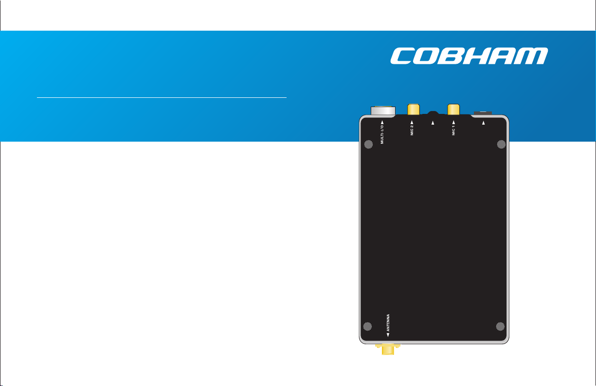
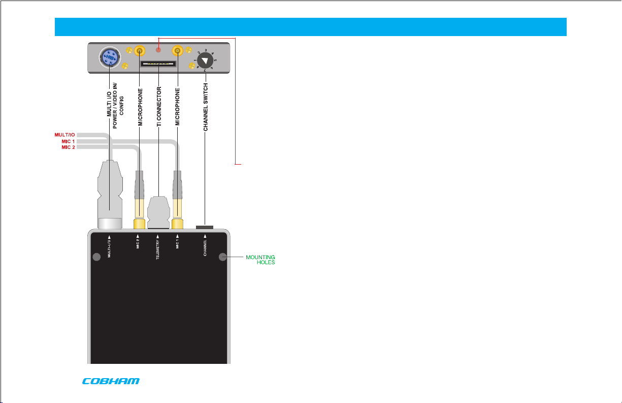
Antenna Connector
Palladium Pd2-TX-100 Transmitter,
Front View
5
INTRODUCTION
TELEMETRY
CHANNEL
Palladium II
VIDEO TX
Audio
Palladium II
The Palladium II Series of digital video transmitters provide exceptional video quality in high
multipath environments. They are ideal for use inside buildings, in urban areas, and in other
applications where multipath would normally cause video tearing or breakup.
All Palladium II Series transmitters offer three bandwidth modes: DVB-T (6, 7, 8 MHz), Narrow
(2.5 MHz), and Ultra Narrow (1.25 MHz) channel spacing. DVB-T utilizes 2000 carriers to
transmit video and two channels of voice and data. Palladium II transmitters may be located
on adjacent channels without a guard band. AES 128-bit encryption ensures users of secure
communications.
The Palladium 100 is a small transmitter with a 100 mW RF power output. This unit is ideal for
concealments and shorter range robotic and UAV applications. The package is only 4.2” x 2.6”
x 0.65” (approximate dimensions not including connectors). Power consumption is 7.5 Watts.
Operation time on a fresh set of Lithium batteries is approximately three hours. All connections
are conveniently located off the ends of the unit. Many users will want to power this device
with disposable batteries.
Palladium Pd2-TX-100
100-Milliwatt Digital Transmitter
6
NOTE: Use only Lithium batteries with this device.

Using your Palladium II Transmitter
Follow the instructions given in the Quick Start section on pages 4-5. When power is first
applied to the Palladium, the unit reverts to the indicated channel and RF ON state. The Alarm
LED may be ON, which indicates that there is no active video input.
Changing your Transmitter Configuration
The Palladium Transmitter can store up to 8 different configurations, which can be selected
with the Channel Control. Each of these configurations can be programmed into the
Transmitter with the supplied DTC
Programming Software and a Windows PC. Refer to the Programming section on page 10 for
more information.
To cycle through your preconfigured channels rotate the knob to the next setting.
OPERATION
7
COMPONENTS
Top Controls/Connectors
Multi-I/O Connector The Multi-I/O Connector is covered on page 9.
Data Chaining & Control Connector This connector is normally covered.
Audio 2 (left) and Audio 1 (right/mono) LEMO Conn. These connectors provide the audio
input connections to the transmitter. Either one or two audio inputs can be used with the
Palladium II Transmitter.
ALARM LED This red LED indicates a valid video signal is not present.
8
 Loading...