

DTC Communications PD2TX1000S Users manual
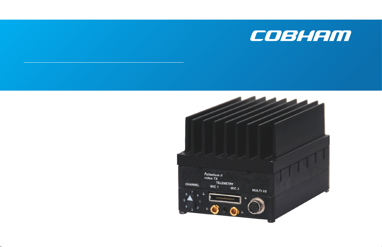
Palladium II Digital
COFDM Transmitter
Model Pd2-TX-1000 1W Output
The most important thing we build is trust

how to contact COBHAM
For operator and troubleshooting
information, customers are encouraged
to refer to the details in this manual. For
additional clarification or instruction, or to
order parts, contact COBHAM.
Customer Service is available Monday
through Friday between the hours of 9:00
AM and 5:00 PM EST at:
Tel: 603-880-4411
Fax: 603-880-6965
Website: www.cobham.com/tcs
Email: dtc.info@cobham.com
DTC Communications, Inc.
dba Cobham Tactical Communications and
Surveillance
486 Amherst Street
Nashua, New Hampshire 03063
copyright notice
Copyright © 2011
COBHAM All rights reserved. No part of this
document may be reproduced, transmitted,
transcribed, stored in a retrieval system or
translated into any language or computer
language, in any form or by any means,
including but not limited to electronic,
magnetic, mechanical, optical, chemical,
manual or otherwise, without the prior
written permission of COBHAM.
disclaimer
The information in the document is subject
to change without notice. COBHAM
makes no representations or warranties
with respect to the contents hereof, and
specifically disclaims any implied warranties
of merchantability or fitness for a particular
purpose. COBHAM reserves the right to
revise this publication and to make changes
from time to time in the content hereof
without obligation of COBHAM to notify
any person of such revision or changes.
2
PN OP1920331-S REV 0.002

manual conventions
NOTE: Describes special issues you should be aware of
while using a particular function.
WARNING: Calls out situations in which
equipment could be damaged or a process could be
incorrectly implemented, but in which operator safety is
not a factor.
TIP: Describes application hints.
RF EXPOSURE STATEMENT
A separation distance of at least 20 cm must be
maintained between the antenna and the body of
the user or nearby persons. When the unit is used
consistent with the previous notice, it conforms to
the requirements of FCC Rules & Regulations, sections
1.1307 & 2.1091, as required by section 90.1217.
CAUTION! Use of antennas with gain above 2.1 dBi may
exceed Maximum Permissible Exposure (MPE) limits.
NOTE: This device is for occupational use only.
Occupational users are those persons who are exposed
as a consequence of their employment, provided these
persons are fully aware of and exercise control over
their exposure.
TABLE OF CONTENTS
Quick Start ....................................................................................................................4-5
Accessories ........................................................................................................................ 5
Introduction ........................................................................................................................ 6
Operation ........................................................................................................................ 7
Using your Palladium II Transmitter .............................................................................. 7
Changing your Transmitter Configuration .................................................................7
Heat Sink ....................................................................................................................8-9
Components .............................................................................................................. 10-11
Programming ......................................................................................................................11
Specifications ..............................................................................................................12-13
Notes ......................................................................................................................14
Contact Us ......................................................................................................................15
NOTE: DO not allow the device to directly contact the
skin due to warm operating temperatures.
3
QUICK START
A1
R/M
A2
L
2
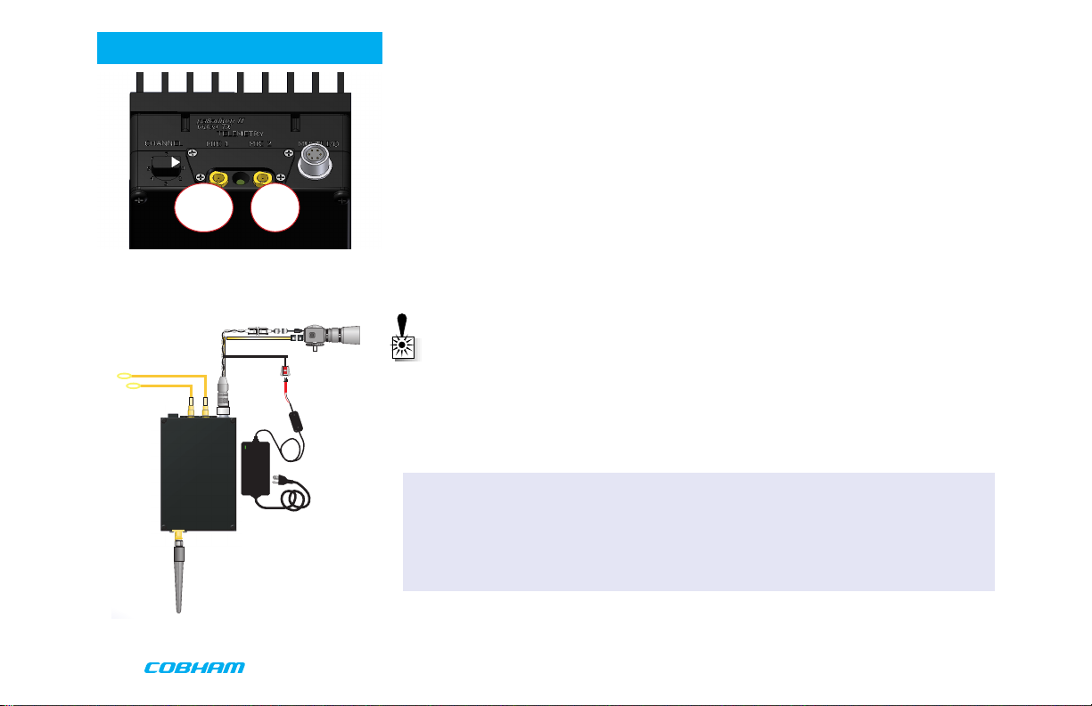
Palladium Transmitter, Top View
Audio
Antenna
3
Power Option
Power Supply
Camera
Complete these steps:
1. Connect the transmitter antenna to the SMA connector on the Palladium unit.
2. If you plan to use audio, connect one or two microphones to the Audio 1 and/or Audio 2
LEMO connectors. If using monaural, use Audio 1.
3. Connect power and video input via the Multi I/O cable to the 6-pin Hirose connector:
a. Attach your camera video input (75 ohm composite video source in PAL or NTSC) to
the Multi I/O cable BNC connector.
b. Apply the necessary power to your camera (use supplied cable or external source) and
turn ON.
c. Attach a 12 VDC power source to the Multi I/O cable via the Molex connector. The
input voltage range is from 10 to 16 VDC.
WARNING: Do not apply power to the transmitter unless an antenna or non-radiating
load is connected to the Antenna SMA connector.
Thermal Issues
Proper heat sink mounting is recommended for optimal performance. See page 8 for heat
sinking instructions.
Typical Wiring Configuration
4
4 Set to the required configuration as indicated by the channel numbers. Refer to the
Programming section on page 10 for more information on channel settings. Your
Transmitter is now operational. Confirm its signal with your Palladium Receiver.
Accessories
• 12 VDC 2.5A Power Supply & AC Line Cord
• Microphone, Body-Worn, (2)
• Power & Video Cable
• Camera Power Cable (2.1 mm plug)
• DC Power Cable, flying lead
• Camera Power Cable, flying lead
• Programming Cable
• Antenna, ANT2A
• 16-Pin Data Chaining & Control Connector Cable
• Transport Case
QUICK START
4
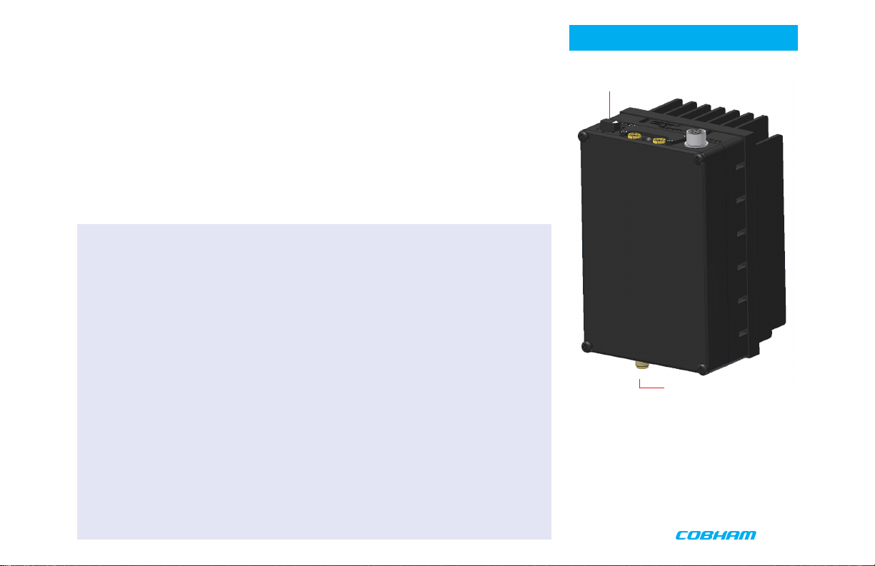
Antenna Connector
Palladium Pd2-TX-1000 Transmitter,
Front View
5
 Loading...