

DTC Communications DSS900TX Users Manual

DSS-900-KT Digital Spread Spectrum Surveillance System 1
Quickstart: DSS-900-KT Surveillance System
Quickstart guides the experienced surveillance professional in rapid setup
and use of the DSS-900-KT. The following table guides you through set up of
the TX, RX and recording functions of the DSS-900-KT.
Step
No.
1.
2.
3.
4.
5.
6.
7.
8.
Step Reference Quickstart Action
Select power
source.
Connect the RX to either an
external AC or DC source.
Install RX antenna. Connect directional high-gain
For Details
See Page
6
12
patch antenna, or omnidirectional disguised cellular
magnetic mount antenna to RX.
Choose agent’s
microphone.
Use the built-in top fire mike on
the TX, or plug in one of the
13
external mikes.
Get a tape. Load tape into the Marantz.
8
Make sure that:
• The tape is fully rewound.
• You are not about to
overwrite an existing
recording.
• The tape is not write
protected.
Enable recorder. Turn the Marantz power ON. 14
Select headsets or
the speaker.
Decide to use the speaker, or
plug one or two headsets into the
9
matching jacks. This disables the
speaker.
Turn TX on. Slide TX power to ON. 13, 14
Set sound intensity. Set the VOLUME to mid-range. 7
Quickstart: DSS-900-KT Surveillance System

2 DTC Communications, Inc.
Step
No.
9.
10.
11.
12.
13.
14.
Step Reference Quickstart Action
Select a method for
recorder control by
using the POWER
switch in the RX
RECORDER section.
Utilize extra outputs
for additional
MANUAL: Record Mode activate is
controlled at the Marantz.
AUTO: Record Mode activate is
controlled by audio squelch level
on the DSS-900-KT RX.
Connect extra recorders to VCR
and SPARE RECRDR output jacks.
original audio
recordings.
Choose your alarm
type with the MODE
SELECT switch in the
RANGE section of
the RX.
OFF: Latching ALARM LED only.
No beep tone; no alarm tone.
BEEP TONE: The higher the beep
pitch, the closer the range.
ALARM ONLY: Steady audible
alarm if the RX loses lock on the
TX signal. You can reset the tone
only by rotating the MODE SELECT
switch to OFF or by regaining
adequate signal strength.
Check the vertical
string of alarm
Keep as many LEDs lit - green,
yellow and red - as possible.
LEDs.
LEDs drop to the
yellow zone.
If red LEDs only
appear.
Immediately close range to the
agent.
Reposition agent or get RX
closer. You are about to lose all
audio!
For Details
See Page
8
14
10
11
15
11
User’s Manual March 1999
DSS-900-KT Digital Spread Spectrum Surveillance System 3
System Overview
Your DTC-900-KT enables communication from a bodywire or internal
microphone on the battery powered TX (transmitter) unit to a briefcase
receiver/recorder. The DSS, digital spread spectrum, transmission technique
is explained in detail in the DSS-900-KT Product Data Sheet. You can obtain a
copy of this sheet from your DTC representative, but you do not need to know
these details to use the equipment.
However, there is one point of major importance that you must know when
using digital spread spectrum transmission device:
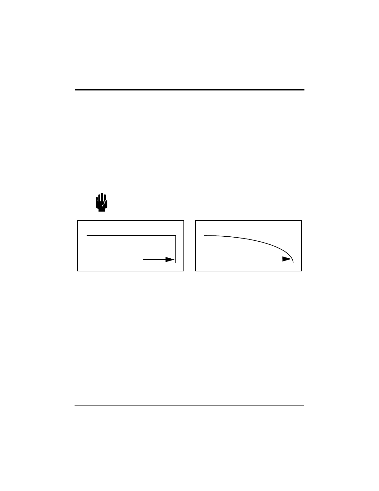
CAUTION With digital spread spectrum, the signal does not
degrade slowly with range: Audio is present and
perfect, or it’s gone!
This go/no-go situation is diagrammed in Figure1.
Audio Signal Level
Range for DSS Signal
Audio Signal Level
Range for Analog Signal
Figure 1Reception Distances for DSS and Analog Transmission
With an Analog Signal, the quality of reception shown in the right side of
Figure1 gradually drops off as you move further away from the transmitting
point or when the transmitter and receiver antennas are not pointed at each
other.
As the left side of Figure1 shows, a Digital Signal provides perfect reception
until a threshold is reached, and then audio is totally lost. The DTC-900-KT
RX has signal strength LEDs on its front panel as well as an audible alarm
that must be monitored to keep you within listening range and direction.
Remember: Watch the green, yellow and red string of LEDs, and do not
disable the audible tone except when security so requires. When the LEDs
drop into the yellow zone, you may lose audio at any time. Close the range to
the agent.
System Overview
4 DTC Communications, Inc.
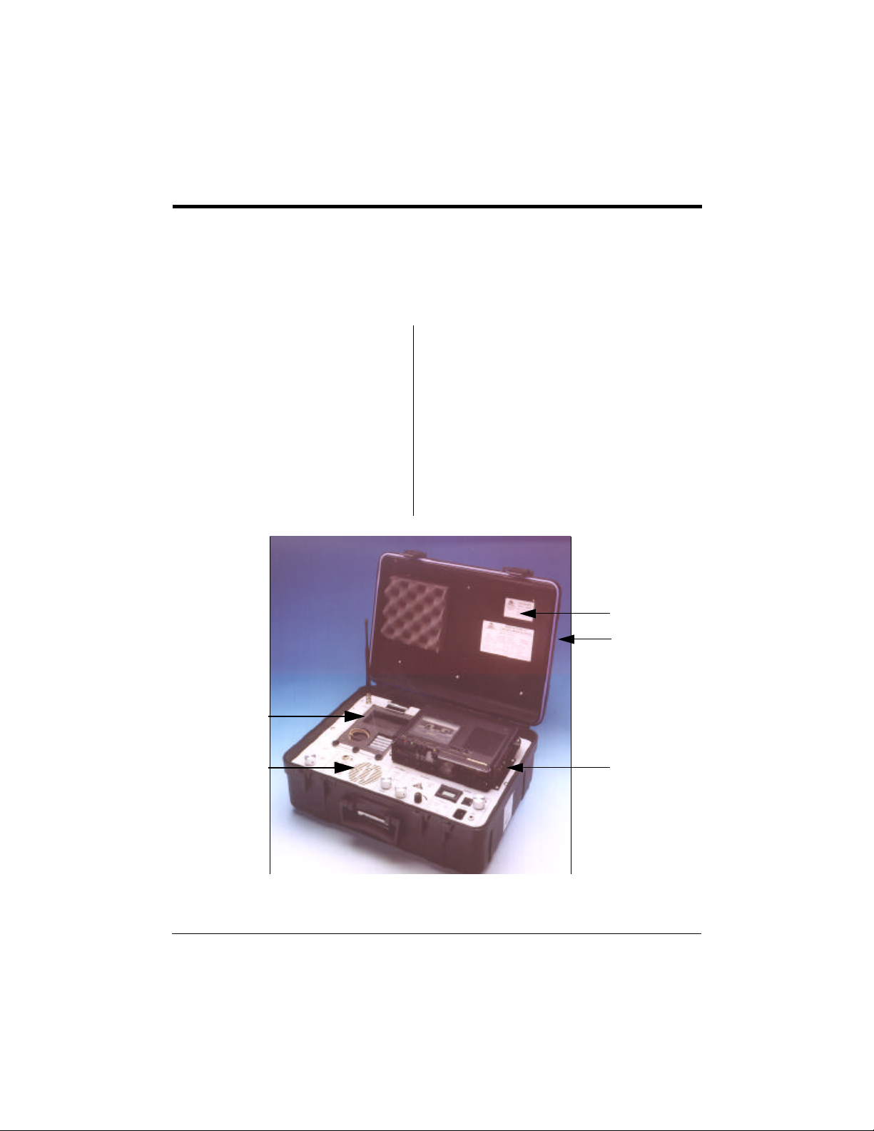
Kit Components
The system is packaged in a rugged carrying case (Figure2) and in a fabric
accessory pouch mounted on the outside of the case cover.
COMPONENTS IN THE BASE COMPONENTS IN THE ACCESSORY POUCH
1. RX panel
2. TX and components:
AAA alkaline batteries, qty. 5
External microphone
3. Frequency-Channel No. label
4. Cover-mounted accessory
pouch
5. Marantz tape recorder
8,9
• RX patch antenna with Mafer
universal clamp
• Cable for RX patch antenna
• Magnetic mount RX antenna
• Stereo headset
• AC and DC power cables
• Marantz recorder manual and this
User’s Manual
6
3
4
(pouch on
top of cover)
5
2
2
1
4
1
5
7
3
Figure 2Principal Components in the Carrying Case
User’s Manual March 1999
DSS-900-KT Digital Spread Spectrum Surveillance System 5
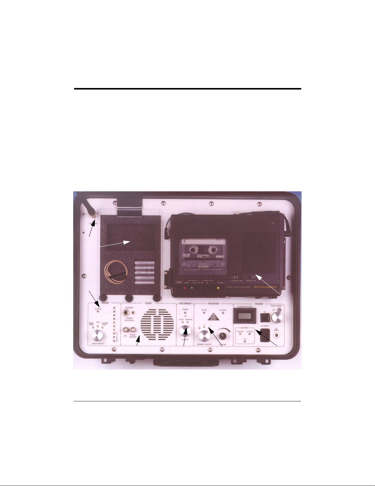
Using the Receiver
Receiver Controls
The main panel within the case of the DSS-900-KT is divided into eight
segments as called out in the photograph of Figure3.
1. Power segment 5. Range/Alarm segment
2. Receiver segment 6. TX, microphone and batteries
3. Recorder segment 7. RX Antenna connector
4. Audio segment 8. Marantz tape recorder
7
6
5
8
4 3 2
1
Figure 3Main Panel of the DSS-900-KT
Using the Receiver
 Loading...