

Page 1
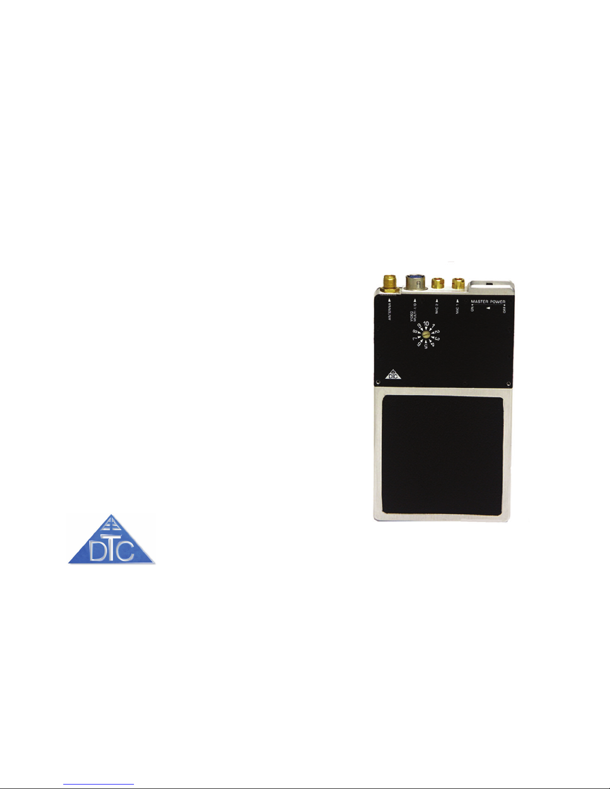
DTC COMMUNICATIONS INCORPORATED PN OP1920256 REV6
VBS2-250 Frequency 2200-2300 MHz
VBS-250 Frequency 2400-2500 MHz
VBL-250 Frequency 1700-1850 MHz
1/4 W1/4 W
1/4 W1/4 W
1/4 W
att, Body Watt, Body W
att, Body Watt, Body W
att, Body W
ornorn
ornorn
orn
VV
VV
V
ideo Tideo T
ideo Tideo T
ideo T
ransmitterransmitter
ransmitterransmitter
ransmitter
ManualManual
ManualManual
Manual
Page 2

DTC COMMUNICATIONS, INC.
2
How to contact DTC
For operator and troubleshooting
information, customers are encouraged to refer to
the details in this manual. For additional clarification
or instruction, or to order parts, contact DTC.
Customer Service is available Monday through
Friday between the hours of 9:00 AM and 5:00 PM
EST at:
Tel: 603-880-4411
Fax: 603-880-6965
Website: www.dtccom.com
Email: [email protected]
486 Amherst Street
Nashua, New Hampshire 03063
USA
Copyright Notice
Copyright © 2002
DTC Communications, Inc. All rights
reserved. No part of this document may be
reproduced, transmitted, transcribed, stored in a retrieval system or translated into any
language or computer language, in any form or by
any means, including but not limited to electronic,
magnetic, mechanical, optical, chemical, manual or
otherwise, without the prior written permission of DTC
Communications, Inc.
Disclaimer
The information in the document is subject to change
without notice. DTC makes no representations or warranties with respect to the contents hereof, and specifically disclaims any implied warranties of merchantability or fitness for a particular purpose. DTC reserves
the right to revise this publication and to make changes
from time to time in the content hereof without obligation of DTC to notify any person of such revision or
changes.
Trademarks
Trademarks of DTC Communications, Inc. include:
• DTC
• MiniPIX
®
• DynaPIX
®
Other product names used in this manual are the properties of their respective owners.
Warranty
DTC warrants its manufactured components against
defects in material and workmanship for a period of
two (2) years, commencing on the date of original purchase.
Products manufactured by others that are approved
for use with DTC equipment are warranted for the
manufacturer’s warranty period, commencing from the
date of shipment from DTC.
FCC information
The following information is provided as a
service to our law enforcement customers who
require a Part 90 station license for video
surveillance operations using the 2450 to 2483.5 MHz
band.
You will need to provide:
• Form 600 (the application form)
Forms can be obtained from the FCC on their website at:
www.fcc.gov
You can also contact the FCC using their FAX back
service at: (888) 418-3676
Additional instructions are available by telephone at:
(888) 225-5322
The filing fee form is returned to:
Federal Communications Commission
1270 Fairfield Road
Gettysburg, PA 17325-7245
Page 3

DTC COMMUNICATIONS, INC.
3
Manual Conventions
NOTE Describes special issues you should be aware of
while using a particular function.
WARNING Calls out situations in which equipment
could be damaged or a process could be incorrectly
implemented, but in which operator safety is not a
factor.
TIP Describes application hints.
TABLE OF CONTENTS
RF EXPOSURE STATEMENT
When used as directed, the maximum SAR of this device is
2.7 W/kg, which meets the limits set forth by the FCC. Refer
to Appendix A in this manual for instruction in the proper use
of antennas with this device.
Quick Start ........................................................................... 4
Overview .............................................................................. 5
Features ............................................................................... 6
Specifications ....................................................................... 7
Battery Drain ........................................................................ 9
Connectors ......................................................................... 10
Connections ........................................................................11
Equipment Configurations ................................................. 13
Optional Accessories ........................................................ 14
Programming ..................................................................... 22
Appendix A ......................................................................... 26
FCC ID# H25VXS250
Page 4
DTC COMMUNICATIONS, INC.
4
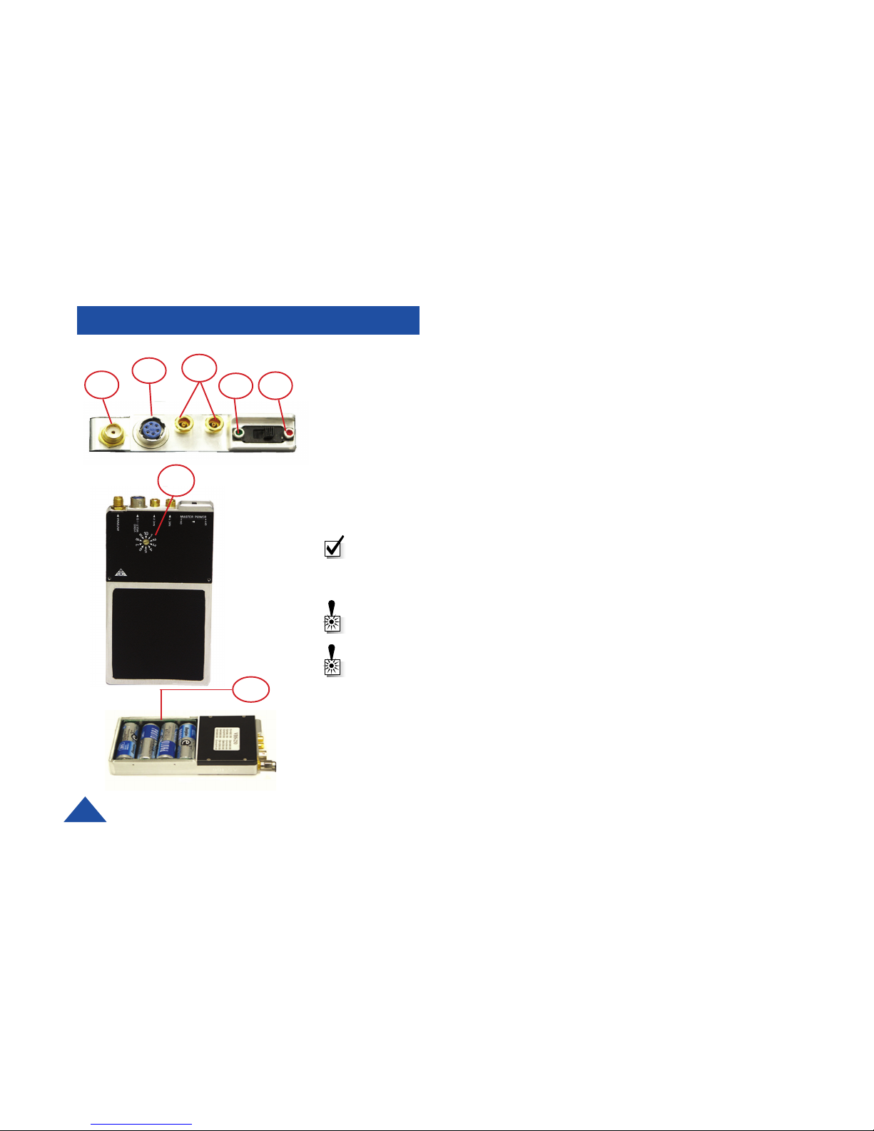
QUICK START GUIDE
1 Make sure that the ON/OFF switch is set to OFF. (Red dot is OFF).
2 Install 4 “AA” batteries in the internal battery compartment of the module.
(Lithium batteries are recommended)
3 Using a screwdriver, turn the channel selector to the correct transmission
channel number.
4 Connect an antenna to the ANTENNA connector on the module.
5 Connect the microphone or microphones to the MIC-1 and MIC-2 connectors
on the module.
6 Connect a video source to the Video/Multi I/O connector.
7 Slide the power switch to the ON position (Green dot is ON) to apply power to
the transmitter.
Note: While installing the batteries, observe proper polarity as printed in the
battery compartment. Reverse polarity protection is a built-in design feature of
the transmitter. If a battery is installed backwards, this feature prevents the
transmitter from powering up, without damaging the transmitter or battery.
Warning: Do not apply power to the transmitter until an antenna has been
connected in step 4.
Warning: Refer to Appendix A of this manual for information on the proper
use of antennas.
5
7 1
4
6
3
2
Page 5

DTC COMMUNICATIONS, INC.
5
OVERVIEW
What should you expect to receive with your 250mW
Transmitter?
1 VBS/VBL Video Transmitter
1 Dipole antenna with right angle SMA connector
1 One Video and Power In “Y” cable
1 DTC programming software package
1 DTC programming cable
8 Batteries
NOTE: The dipole antenna included is not recommended for normal
use! This antenna enables you to quickly set up your transmitter
and ensure proper operation. DTC highly recommends the use of
circularly polarized antennas for the best rejection of multi-path.
NOTE: DTC has provided you with a “Y” cable (power and video)
terminated with an RCA connector and a BNC adapter for your
convenience.)
The VBL/VBS series video transmitters from DTC represent the first true “video body wires” available. DTC has developed a
fully user programmable video transmitter and mated it with an integral AA battery pack. This dramatically simplifies wiring,
lowers the risk of detection, and increases the chances of operational success.
For best results, DTC recommends the use of its VidiWIRE on body dual patch antenna system with phase matching module,
and a DTC diversity receiver.
Users should also consider using the VBL/VBS series transmitters for rapid deployment drop cameras. Packaging the
transmitters with miniature board cameras is exceptionally easy, and in the case of 5 volt cameras, power may be provided to
the camera directly from the VBL/VBS transmitter’s internal battery pack.
This product in only available for sale to legitimate state, local, federal and friendly foreign government agencies.
Page 6

DTC COMMUNICATIONS, INC.
6
FEATURES
Feature Description
Remote Switching Capability
External Power Loop Through
Programmable
Audio
Efficient Switching Power Supply
Camera Power Available through
Multi I/O Connector
• You may turn the device ON remotely, by attaching a switch to one
of the pins on the Multi I/O connector. DTC provides hard-wired and wireless
switches for this application.
• The power applied to the Multi I/O pin is automatically looped through the
unit, and available on a second pin to power a remote device, such as a
camera. If you apply 9 Volts in, you will get 9 Volts out. Applying power through
the multi I/O connector automatically disables the internal AA battery pack.
WARNING: Make sure your camera will operate on the voltage being supplied
to the transmitter.
User programmable video channels, selectable in 250 kHz steps. Two user
programmable audio sub carriers, selectable in 10 kHz steps from 6 MHz to
7.5 MHz.
• Audio sub carriers are OFF unless microphones are attached. The
transmitter automatically senses when a microphone has been attached.
• The audio sub carriers are phase locked, and will not drift into the video
signal.
• Automatic Gain Control is provided on each audio input, amplifying soft
sounds.
• They generate far less heat than a traditional video transmitters.
• They operate significantly longer than traditional video transmitters on the
same power source.
• When powering the device using the internal battery pack, regulated 5 VDC is
available on the multi I/O connector, limited to 200 mA current drain.
Page 7
DTC COMMUNICATIONS, INC.
7
SPECIFICATIONS
Specifications for the body worn VBS/VBL-250
Power Supply Internal batteries 4 “AA” batteries or external 9-16 VDC.
Power Consumption 2.5 Watts (not including camera)
Battery life 3 hours - Alkaline AA
Reverse polarity
protection Yes
Dimensions 2.5 x 4.5 x 0.675”
Camera Power Using external power input: Same as supply voltage,
switched (200 mA max)
Using internal batteries: 5 VDC @ 175 mA, switched
(internal regulator)
Controls 10 channel select rotary switch
Panel mounted, slide ON/OFF switch
Connectors 2 pin Lemo: Mic 1
2 pin Lemo: Mic 2
SMA: Antenna
6 pin Multi I/O: Video in, Data in, DC input 9 -16 VDC,
camera power, Remote ON/OFF, Multiplexed Data out,
Ground
Programmability Video: 2400 - 2500 MHz (VBS-250)
1700 - 1850 MHz (VBL-250)
250 KHz resolution steps
Audio: User programmable from 6.0 - 7.5 MHz, in
10 kHz steps
Chassis notes Machined solid aluminum with rounded edges.
Audio
General Mic level input (line level factory opt.) 50 - 3000 Hz
Phased locked with AGC on both inputs. Sub-carrier auto
sensing, only active when microphone is attached.
Number of sub-carriers 2
Sub-carriers frequencies 6.0 - 7.5 MHz , user programmable
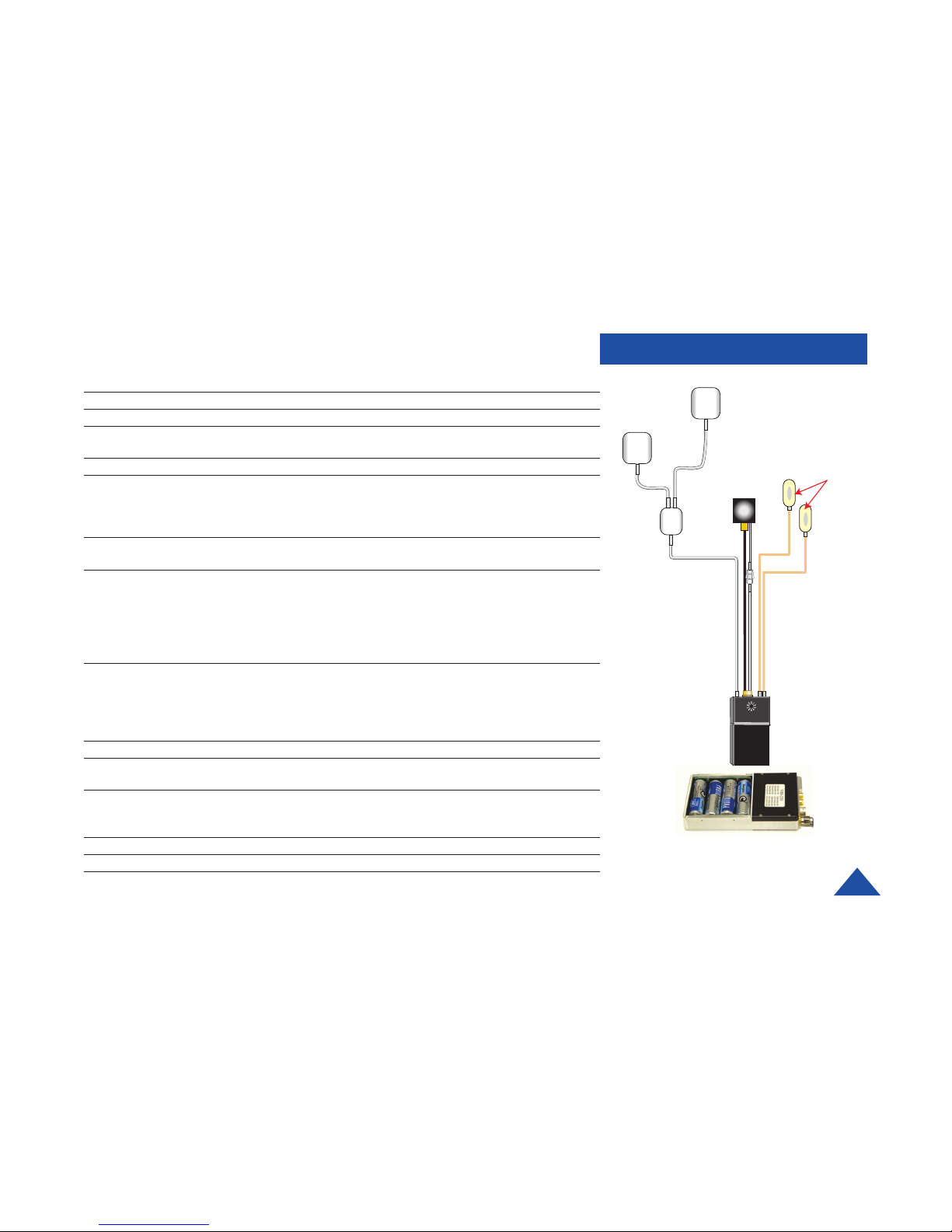
Four lithium “AA” batteries
FRONT PATCH
ANTENNA
BACK PATCH
ANTENNA
SPLITTER
CAMERA
MICROPHONES
TRANSMITTER
Page 8
DTC COMMUNICATIONS, INC.
8
SPECIFICATIONS
Sub-carrier ON/OFF
control Subcarriers are activated when mic is connected.
Subcarrier frequency
stability +/- 0.003%, -30°C to +70°C
Sub-Carrier Deviation 50 kHz peak
Audio S/N 45 dB min.
Frequency Response BW
1.5dB
= 50 - 3000 Hz
Total Harmonic Distortion <2%
Input Level 8 mVpp @ 400 Hz for 50 kHz peak dev.
Pre-Emphasis 75 uS
Input Impedance 10 k Ohm
Video
Video Frequency
Response BW
1.5dB
= 6 Hz - 5.0 MHz
Input Impedance 75 Ohms
Input Level 1V
p-p
Max.
S/N 60 dB min.
Pre-Emphasis Per CCIR 405 525 line curve
Differential Gain 5%
RF
Operating Frequency 1700 - 1850 MHz, 250 KHz resolution steps
2400 - 2500 MHz, 250 KHz resolution steps
Power output 250 mW min. @ nominal supply voltage, 25 Deg. C.
-3 dB @ 3.6 VDC int
-2 dB over temp.
Output Impedance 50 Ohms
Spurs and Harmonics
output -50 dBc
Load Pull Stability 8:1 VSWR
Page 9
DTC COMMUNICATIONS, INC.
9
Frequency Stability +/- 0.003%, -30°C to +50°C
Modulation Sensitivity 8 MHz/V nom.
Modulation Sensitivity
Variation +/- 5% across the band
Peak Carrier Deviation 4 MHz nom.
Number of channels 10 max. (user programmable)
Sub-carrier sideband
level -28 dBc, +/- 2 dB
Environmental
Temperature Range -30°C - +70°C
Humidity 90% (non-condensing)
SPECIFICATIONS
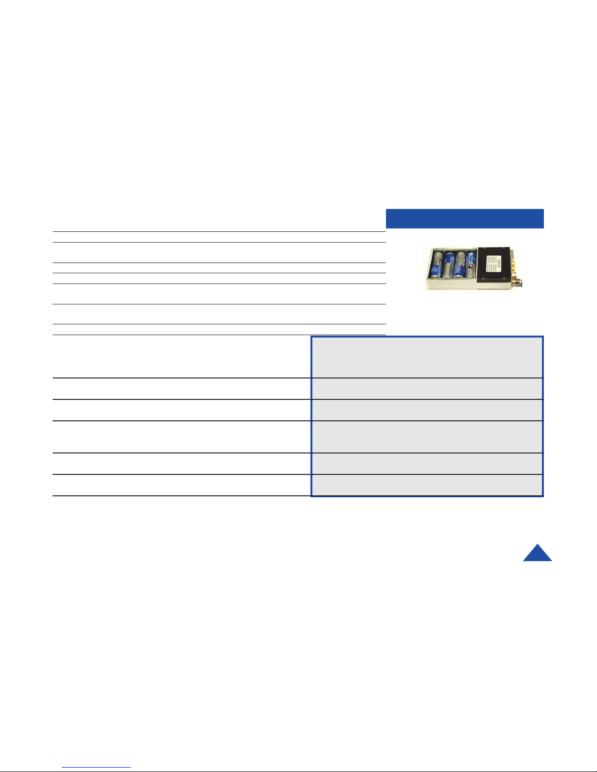
Four lithium batteries
Transmitter & Camera
Battery Type Part Number Transmitter Only Camera 9V@153mA Camera 12V@120mA
9 AA Alkaline Pack 4045131 6 hours 3.3 hours 3.6 hours
(External)
9 AA Lithium 4045132 9 hours 5 hours 5.5 hours
(External)
9 AA NiMH 4045130 7 hours 4 hours 4.3 hours
Rechargeable
(External)
4 AA
(Internal)
4 AA Lithium
(Internal
Page 10
DTC COMMUNICATIONS, INC.
10
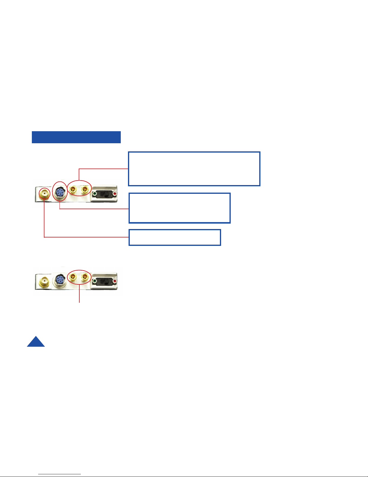
MICROPHONE CONNECTORS
Two connectors accommodate two microphone inputs. Each connector has two
contacts and provides power to the microphone as well as connecting the audio
signal into the transmitter. The audio sub-carriers are activated by the presence of the
microphone. If a microphone is removed, that sub-carrier is removed from the
transmit signal. Turning off the unused sub-carrier saves power and improves picture
quality.
CONNECTORS
Microphone Connectors
Lemo Male Part # (FFS.01.250.DLAE31)
DTC Male Part # (8570003)
Hirose Part # HR10A-7P-6P (02)
DTC Part # 954020
Standard Male SMA connector
MATING CONNECTORS
Page 11
DTC COMMUNICATIONS, INC.
11
ANTENNAS
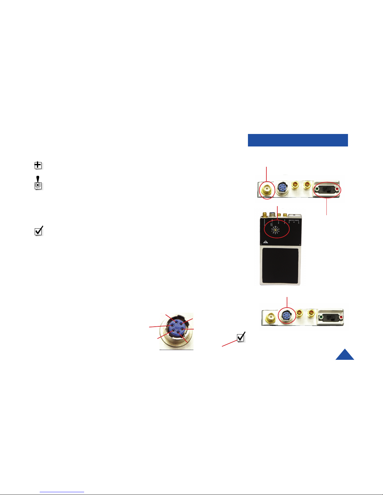
A standard SMA connector is used as the antenna connector on both the VBS/VBL-
250. Refer to a list of DTC antennas available beginning on page 18.
TIP: You may use the VBS/VBL series transmitters with other manufacturers
antennas. Verify that they are suited for the band you are operating in.
WARNING: Refer to Appendix A of this manual for information on the proper use
of antennas.
CHASSIS MOUNTED POWER ON/OFF SWITCH
A slide switch is provided for local control of power ON and OFF. Green dot is ON,
Red dot is OFF.
NOTE: REMOTE ON overrides the chassis mounted OFF switch. (i.e. When the
chassis mounted power switch is set to OFF, REMOTE ON can be used to turn
the transmitter ON.)
CHANNEL SELECT SWITCH
Select a transmission channel by using the rotary switch located on the front surface of
the transmitter. Use a screwdriver to rotate the switch to the desired channel number.
MULTI I/O CONNECTOR
The multi I/O (6-pin Multi I/O) connector is mainly used as the video and external
power input connector. It also provides access to many transmitter functions, such as:
• Programming the device
• Video in
• Power in
• Remote on
• Camera power
CONNECTIONS
On/OFF
Switch
Antenna Connector
Channel Select
Multi I/O Connector
NOTE: Same as supply voltage. Do
not exceed 200mA.
Pin 3: Camera
Power Output
Pin 1: Ground
Pin 2: Ext power
input 9-16VDC
Pin 6: Video in
Pin 5: RS-232 in
Pin 4: Remote on,
switched to ground
Page 12
DTC COMMUNICATIONS, INC.
12
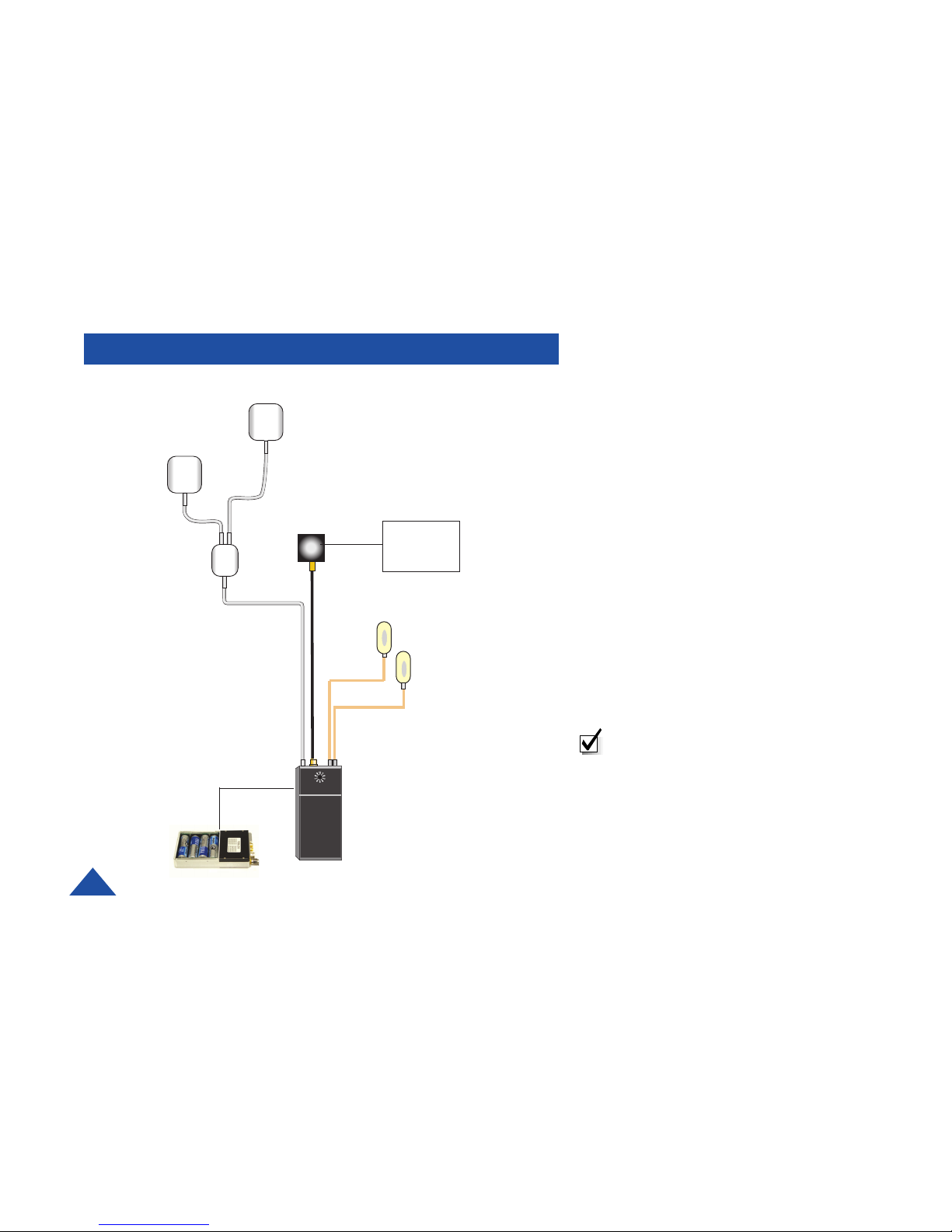
EXTERNAL CAMERA POWER
TRANSMITTER
SPLITTER
CAMERA
FRONT PATCH
ANTENNA
BACK PATCH
ANTENNA
MICROPHONE
MICROPHONE
+
-
The basic VBS/VBL-250 configuration
consists of the video transmitter, Vidi-Wire
Antenna, and DTC cable part number
4045170-024. This cable is connected to the
multi I/O port of the transmitter, and is
configured to supply:
• The video signal from the camera to the
transmitter.
• Power to the transmitter through the
internal battery pack.
NOTE: You will need external camera
power if voltage to the transmitter is not
compatible with your camera’s operating
voltage, and/or you need greater battery
life, and/or your camera draws more than
200mA.
Page 13
DTC COMMUNICATIONS, INC.
13
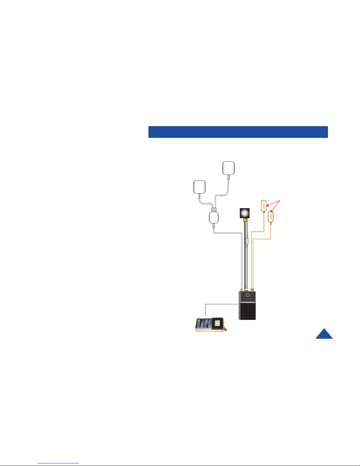
The basic VBS/VBL-250 configuration consists
of the video transmitter, Vidi-Wire Antenna, and
DTC cable part number 4045194-024. This
cable is connected to the multi I/O port of the
transmitter, and is configured to supply:
• The video signal from the camera to the
transmitter.
• Power to the transmitter and camera
through the internal battery pack.
FRONT PATCH
ANTENNA
BACK PATCH
ANTENNA
SPLITTER
CAMERA
MICROPHONES
TRANSMITTER
TRANSMITTER AND CAMERA (INT)
Page 14
DTC COMMUNICATIONS, INC.
14
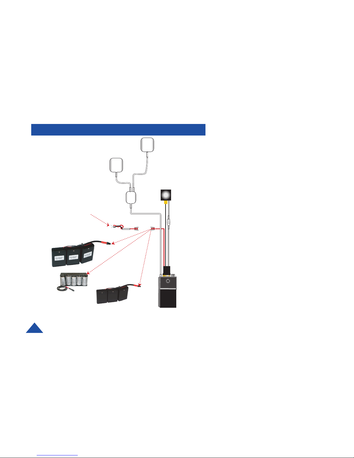
EXTERNAL TRANSMITTER POWER
The VMS/VML-250 configuration, which uses
the loop through power source for the camera,
consists of the video transmitter and DTC cable
part number 4045189-024 . This cable is
connected to the multi I/O port of the transmitter.
It is configured to supply:
• The video signal to the transmitter
from the camera.
• Power to the transmitter through a
molex connector that can be easily
connected to DTC’s battery packs.
• Power to the camera through a
molex connector that can easily be
connected to DTC’s optional
cameras.
CAMERA
ANTENNA
POWER SOURCE
for transmitter only,
9-16 V.
STRIPPED AND
TINNED LEADS
STANDARD
A
B
C
OPTIONAL
BATTERY
PACKS
TRANSMITTE
R
A 4045131 (AA non-rechargeable)
B 4045177( D-Cell battery pack)
Alkaline
C 4045130 (AA rechargeable)
MiMH
Page 15
DTC COMMUNICATIONS, INC.
15
NOTE: You will need external camera power if
voltage to the transmitter is not compatible
with camera’s operating voltage, and/or you
need greater battery life, and/or your camera
draws more than 200mA.
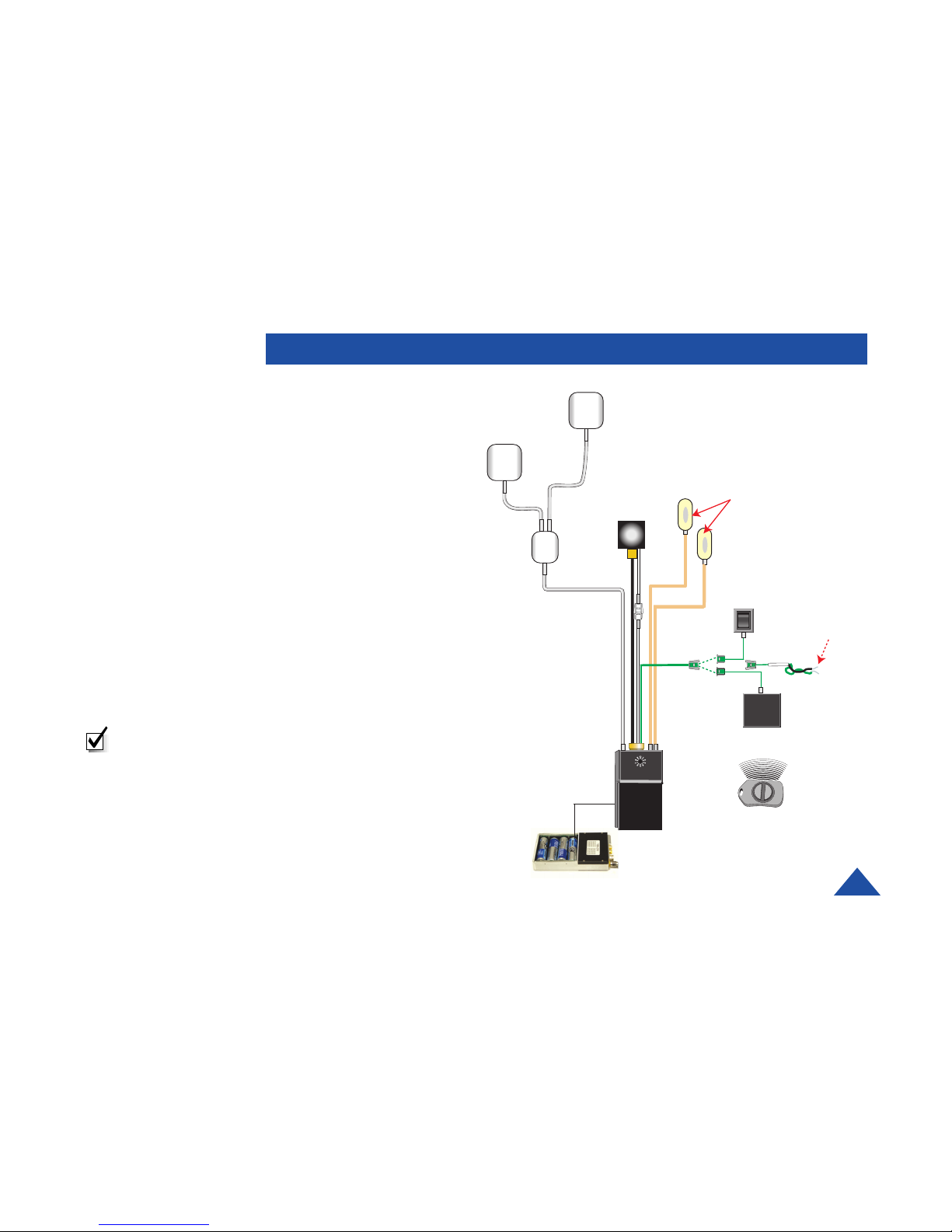
This configuration consists of the video transmitter,
Vidi-Wire antenna, and DTC cable part number
4045192-024. This cable is connected to the multi/
IO port of the transmitter, and is configured to
supply:
• The video signal from the camera to the
transmitter.
• Power to the transmitter and camera through
the internal battery pack.
• Remote on function through a hard wired
switch or remote Key FOB transmitter. This
remote on function overrides the OFF switch
located on the transmitter chassis.
ADDING REMOTE ON FUNCTION TO BASIC
FRONT PATCH
ANTENNA
BACK PATCH
ANTENNA
SPLITTER
CAMERA
MICROPHONES
TRANSMITTER
HARD WIRED
SWITCH
KEY FOB
SWITCH
RECEIVER
KEY FOB
SWITCH
TRANSMITTER
STRIPPED AND
TINNED LEADS
STANDARD
Page 16
DTC COMMUNICATIONS, INC.
16
ACCESSORIES
Part Number Description
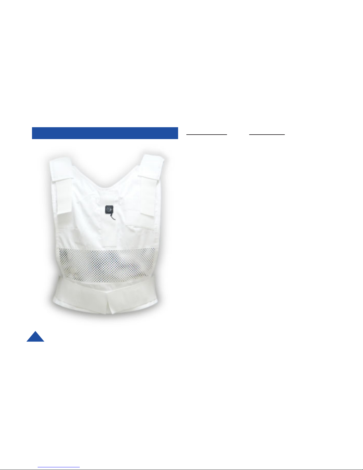
1088185 Vidi Vest™
The VidiVest™ is designed to be used in conjunction with
DTC’s body worn video transmitter. The vest supplies
compartments for the video transmitter, associated wiring,
antenna system (i.e. VidiWire™), microphones, and a button
camera. The garment is ventilated for comfort and can be
adjusted with velcro straps at the waist and shoulders. The
vest is intended to be worn as an undergarment with a loose
fitting shirt or other garment over the vest.
4045181 Camera with 3-pin connector
Assembly
This camera is a high-resolution color CCD type, which has
been modified to look like a shirt button. This allows for easy
concealment through a regular button hole.
4045192-024 VidiVest cable harness
This cable harness connects all of the components, such as,
the transmitter, battery packs, microphones, and VidiWire
antenna system.
Page 17
DTC COMMUNICATIONS, INC.
17
Part Number Description
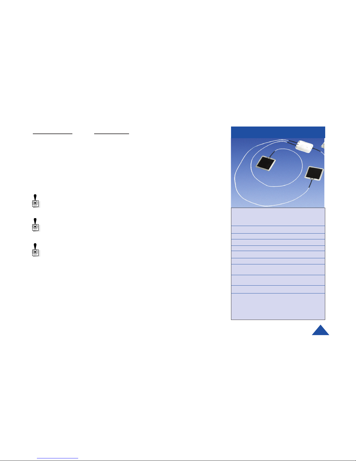
VW-ANT-2-SMA VidiWire antenna system 2.4-2.5 GHz
VW-ANT-1-SMA VidiWire antenna system 1.7-1.9 GHz
The VidiWire™ antenna system was specifically designed for video transmission
from on-body transmitters. This DTC Proprietary system provides the best
possible omnidirectional video transmission from a body-worn system. The
system is composed of three parts: two special patch-type antennas, and a
phasing module.
WARNING: VidiWire Antennas are housed in a milled aluminum cover which
shields the wearer from RF energy. Make sure the antennas radiating side is
directed away from the body.
WARNING: Do not use the VidiWire antenna system on the body with any
transmitter outputting more than 250mW of RF energy.
COMPONENTS
WARNING: Refer to Appendix A of this manual for information on the proper
use of antennas.
Specifications
Type DTC proprietary
VidiWire™ design
Polarization Dual Polarized
Peak Gain Pseudo-Isotropic
Horizontal Beamwidth Omnidirectional
Vertical Beamwidth Omnidirectional
Nominal Impedance 50 Ohms
Groundplane Requirements Not applicable
Size Antennas: 2.0” W x 2.0” H x 0.25” D
(51 mm x 51 mm x 6.35 mm)
Phasing Unit
2.0” W x 1.5” H x 0.25” D
(51mm x 38mm x 6.35mm)
Net Weight 6oz
VW-ANT-2-SMA 2.4 to 2.5 GHz SMA male connector
VW-ANT-2-TNC 2.4 to 2.5 GHz TNC male connector
VW-ANT-1-SMA 1.7 to 1.9 GHz SMA male connector
Page 18
DTC COMMUNICATIONS, INC.
18
ACCESSORIES
Part Number Description
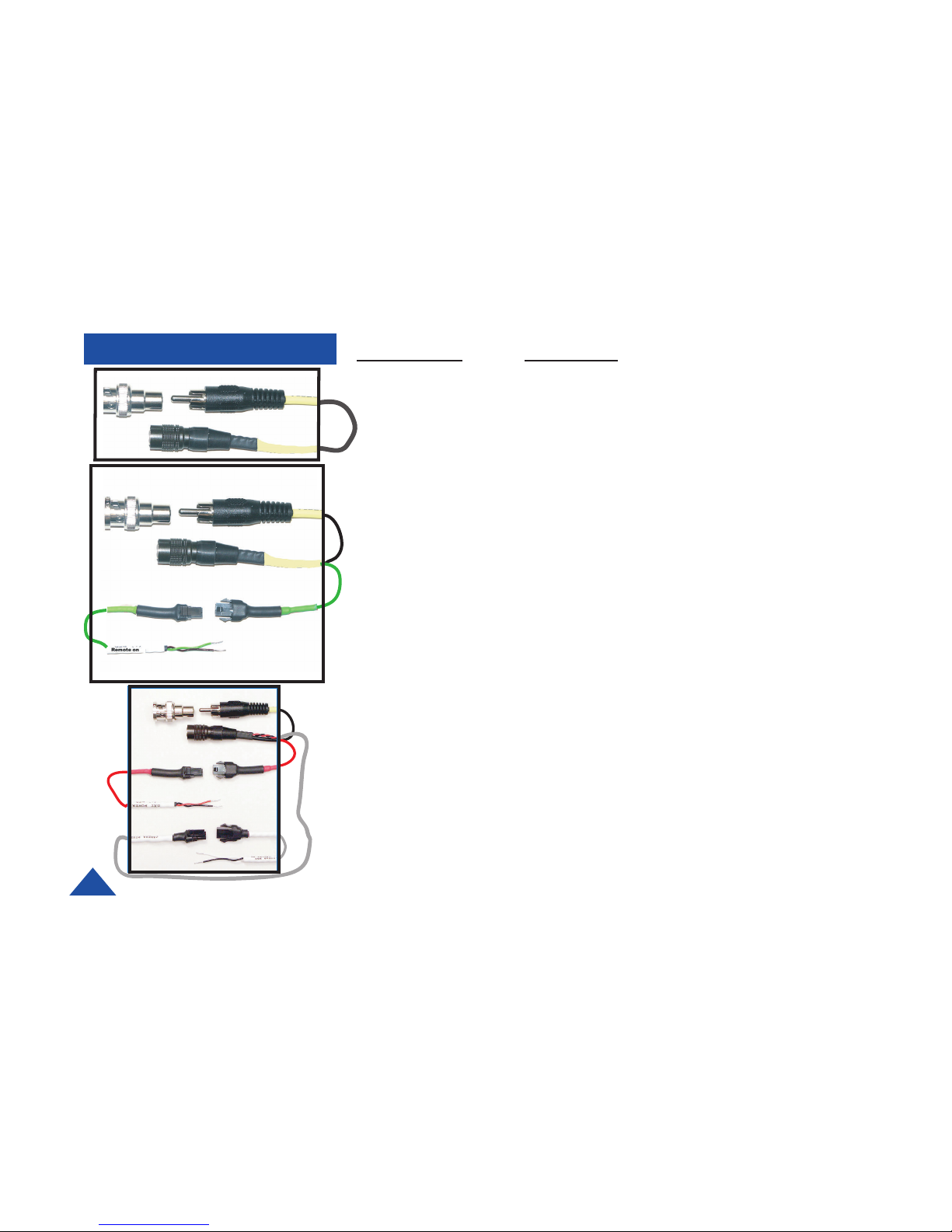
4045170-024 Video In, 24”standard.
Video In: Multi I/O to RCA(M) with BNC
adaptor. (YELLOW)
4045193-024 Video In/Remote On, 24”standard.
Video In: Multi I/O to RCA(M) with BNC
adaptor. (YELLOW)
Remote On: 24 AWG wire with a molex
connector and stripped and tinned leads. (GREEN)
4045189-024 Video In/EXT Power/Camera Power cable, 24”standard.
Video In: Multi I/O to RCA(M) with BNC
adaptor. (YELLOW)
Ext. Power: 24 AWG wire with a molex connector
and stripped and tinned leads. (RED)
Camera Power:24 AWG wire with a molex
connector and stripped and tinned leads.(GRAY)
Page 19
DTC COMMUNICATIONS, INC.
19
ACCESSORIES
Part Number Description
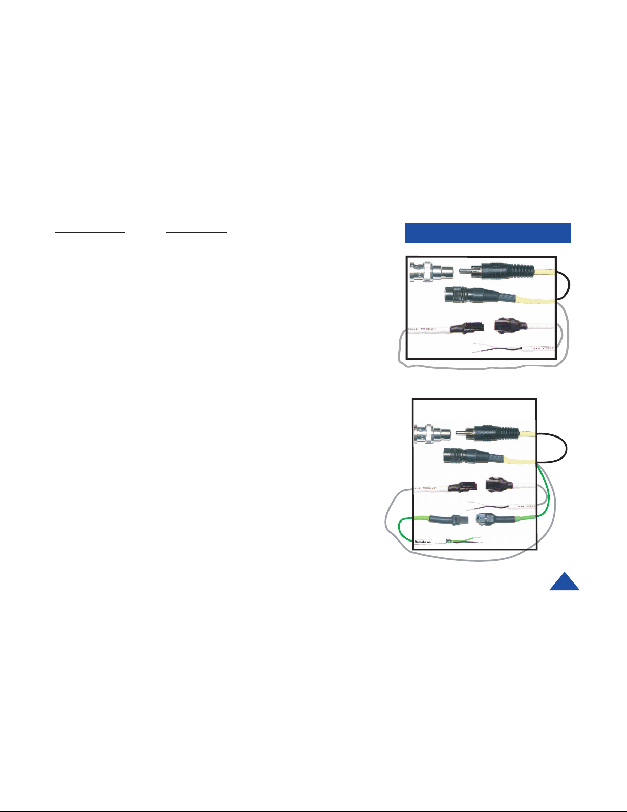
4045194-024 Video In/Camera Power, 24”standard.
Video In: Multi I/O to RCA(M) with BNC
adaptor. (YELLOW)
Camera Power: 24 AWG wire with a molex
connector and stripped and tinned leads. (GRAY)
4045192-024 Video In/Camera Power/Remote On, 24”standard.
Video In: Multi I/O to RCA(M) with BNC
adaptor. (YELLOW)
Camera Power: 24 AWG wire with a molex
connector and stripped and tinned leads.(GRAY)
Remote On: 24 AWG wire with a molex
connector and stripped and tinned leads. (GREEN)
Page 20
DTC COMMUNICATIONS, INC.
20
ANTENNAS
Part Number Description
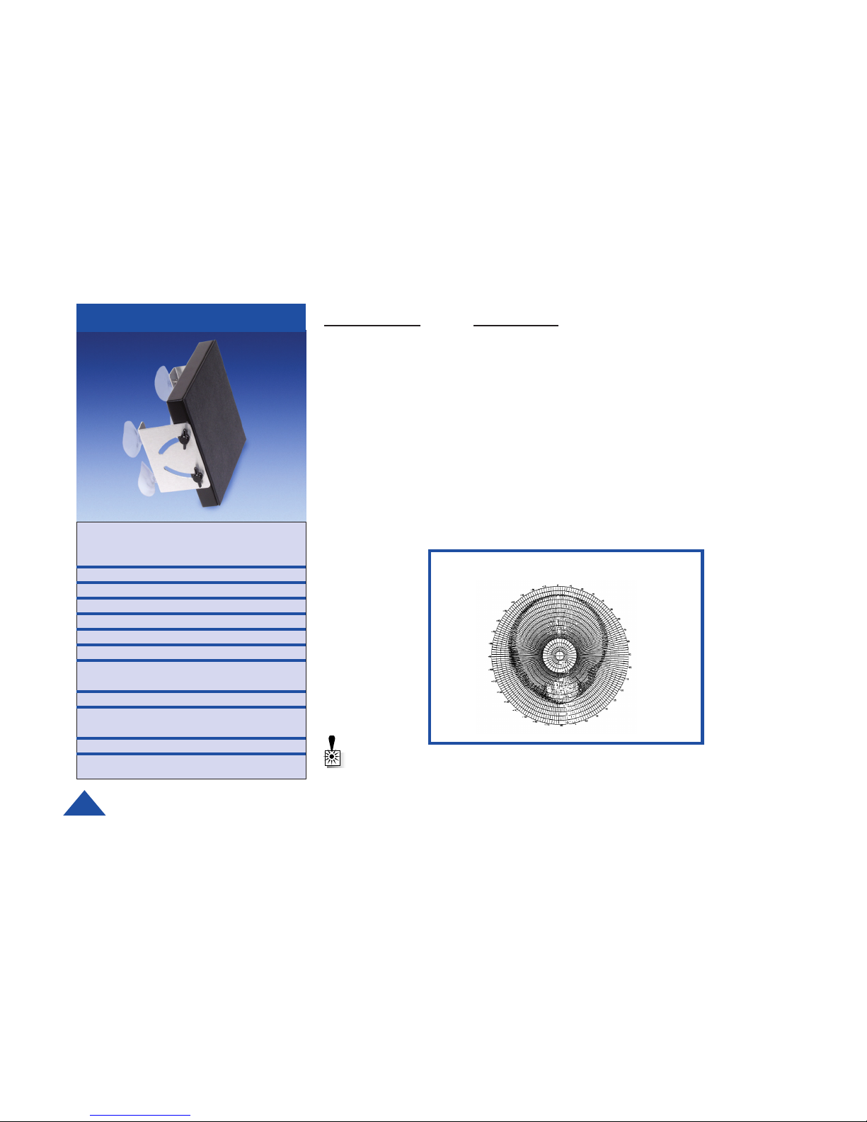
VDAR-1 Single 5 dBic “Hybrid-Patch”™ Antenna with mounting
options.
Connector: TNC Female on chassis
The VDAR video antennas are designed to operate with traditional single video
receivers and multiple antenna configurations for diversity receivers. The antenna
uses the DTC Hybrid-Patch system to ensure high purity circular polarization. This
ensures the highest possible performance in video reception, especially in
diversity systems. It is available in three different bands. Reversible and adjustable suction cup mounts come standard for quick and easy installation on the
inside or outside of window or other hard, smooth surfaces.
VDAR-1
Specifications
Type Three Hybrid Patch™
elements
Polarization RHCP
Peak Gain 5dBic
Horizontal Beamwidth 90°
Vertical Beamwidth 90°
Nominal Impedance 50 Ohms
Groundplane Req. Built-in
Size 6.6” H x 6.6” W
(167mm x 167 mm)
Weight 12 Oz. (34g)
DTC Part Number Frequency Range
7011156-1 1700 to 1850 MHz
7011156-3 1990 to 2110 MHz
7011156-2 2400 to 2500 MHz
WARNING: Refer to Appendix A of this manual for information on the proper
use of antennas.
Page 21
DTC COMMUNICATIONS, INC.
21
ANTENNAS
Part Number Description
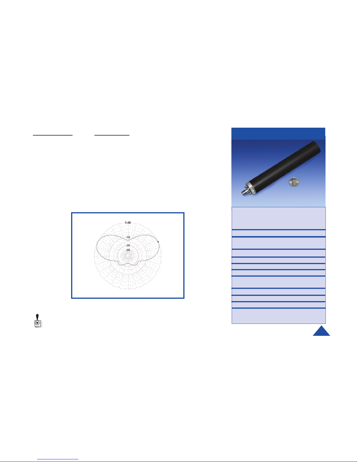
QHA-4 Quadrifilar Helix Antenna with Ring-Hybrid feed
Connector: TNC Female
Must be used with SMA to TNC antenna cable
(4045174-006).
The QHA family of antennas was developed to provide a compact solution for
pattern-tailored circularly polarized antennas. This rugged antenna is omnidirectional when the antenna is vertical. The pattern is slightly elevated to allow
overhead coverage. The base of the antenna includes a special flat with #10-32
threaded hole, 0.25-in. deep for mounting. It is available in both RHCP and
LHCP versions.
WARNING: Refer to Appendix A of this manual for information on the proper
use of antennas.
QHA-4
Specifications
Type Quadrifilar Helix with
Ring-hybrid feed
Polarization Circular
Peak Gain 4dBiC at 24° above
horizon
Horizontal Beamwidth Omnidirectional
Vertical Beamwidth 46°
Nominal Impedance 50 Ohms
Groundplane req. Not Required
Size 8.0” L x 1.25” dia
(203 mm x 32 mm dia)
Weight 3.7 oz. (105 g)
DTC Part Number Frequency Range
QHA-4-2-R 2.4 to 2.5 GHz, RHCP
QHA-4-2-L 2.4 to 2.5 GHz, Lhcp
Page 22
DTC COMMUNICATIONS, INC.
22
ANTENNAS
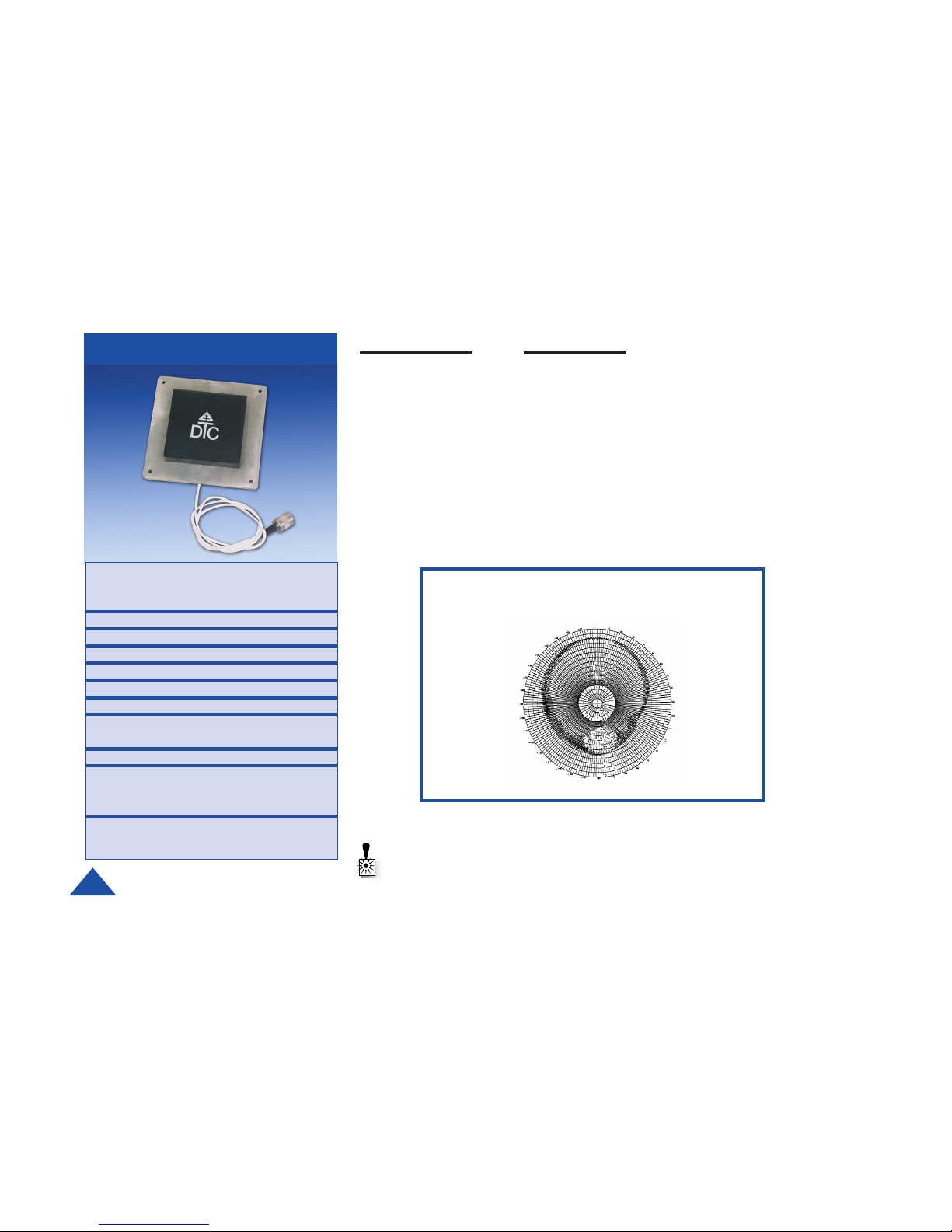
ANT-5-PIG 5 dBi Patch Antenna Connector: SMA or TNC Male on
18" coax. “pigtail”.
DTC has developed a series of circularly polarized patch antennas for use in the
2.0 to 2.5 GHz indoor and short term outdoor installations. The ANT-5-P is a 5dbi
gain, 90 degree wide beamwidth, antenna, mounted on a 0.125 in. thick aluminum plate. Typical uses include disguised transmitters and vehicular-mounted
transmitter antennas and in a variety of receive applications.
Part Number Description
Specifications
Type Patch antenna with integral
ring hybrid
Polarization RHCP
Peak Gain 5dBic
Horizontal Beamwidth 90°
Vertical Beamwidth 90°
Nominal Impedance 50 Ohms
Groundplane Req. Built-in
Size 4.0” W x 4.0” H X 0.625” D
(102mm x 102mm x 16mm)
Weight 6.4 Oz. (180 g)
DTC Part Number Frequency Range
ANT-5-P-SMA 2.0 to 2.5 Ghz with SMA
male connector
ANT-5-P-TNC 2.0 to 2.5 Ghz with TNC
with male connector
WARNING: Refer to Appendix A of this manual for information on the proper
use of antennas.
Ant-5P
Page 23
DTC COMMUNICATIONS, INC.
23
ANTENNAS
Part Number Description
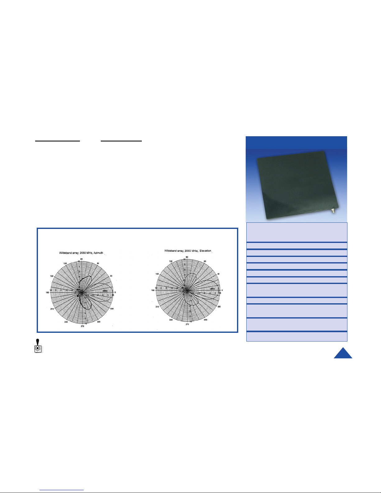
ANT-10 9dBic Wideband Panel Connector: TNC Female
DTC has developed a series of circularly polarized panel antennas for use in
wideband transmit and receive applications from 1.7 to 2.7 GHz. The ANT-10-R
is a very wide bandwidth, unidirectional log-spiral array. This antenna has
useful gain, with some sidelobe variation, to 4 GHz. It can be mounted to a wall
or swivel mounted with the MAF-1 grip on two surfaces, via two pairs of “1/4-20”
tapped holes located in the rear center and the bottom center of the aluminum
housing. The front of the antenna is a radome made of a polycarbonate
material. The antenna is suitable for indoor and short-term outdoor use. It must
be protected for extended outdoor use and installations since it is not water-
Specifications
Type Log-spiral slot array, absorber
loaded
Polarization RHCP
Peak Gain 9dBic
Horizontal Beamwidth 30°at 2.0 GHz
Vertical Beamwidth 30°at 2.0 GHz
Nominal Impedance 50 Ohms
Groundplane Req. Not required
Size 9” W x 9” H x 1.2” D
(227mm x 227 mm x 30 mm)
Weight 1.7 lb. (750g)
DTC Part Number Frequency Range
4044411 1.7 to 2.7 GHz; RHCP
7011142 1.7 to 2.7 GHz; RHCP with
MAF - 1 grip included
WARNING: Refer to Appendix A of this manual for information on the proper
use of antennas.
Ant-10
Page 24

DTC COMMUNICATIONS, INC.
24
Introduction
DTC has built in a lot of flexibility in the programming options you have on the VBL
and VBS series transmitters. You can choose to use some, all or none of this
flexibility.
When you order a VBL or VBS transmitter, DTC will factory program your frequencies at no additional charge to you. You may want to place a sticker over the
rotary switch on the chassis, so users in the field don’t attempt to change frequencies. This is often the best path for state and local agencies with limited frequencies available to them.
DTC will also provide you with free software and a free programming cable,
enabling you to change your video frequencies and their associated audio subcarriers. This is ideal if you often work with other agencies, or anticipate the
equipment being used by a multi-jurisdictional task force. You can program up to
ten channel settings per unit. In general, this allows you to program most variations you might encounter in the field at the depot level.
As a practical matter, your VBL or VBS transmitter’s video frequencies and audio
sub-carriers will be dictated by the frequency and sub-carriers(s) of your receiver
and/or repeater. In many cases, these devices are crystal controlled or have few
channel options.
TIP: Make sure that you program your transmitter to match the frequencies
and audio sub-carriers or your receiver, and test the components as a
system prior to going into the field!
PROGRAMMING
Page 25
DTC COMMUNICATIONS, INC.
25
PROGRAMMING
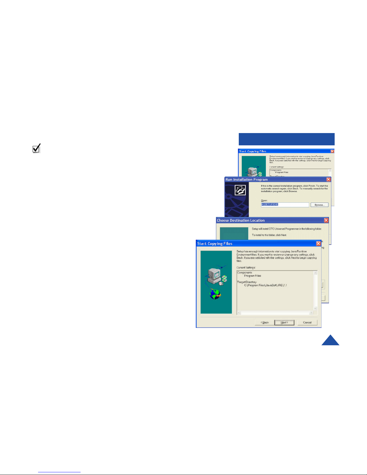
Installing DTC Universal Programming Software on your PC
NOTE: Uninstall any previous versions by going to Add/Remove Programs,
clicking on DTC Universal Programming, and clicking on uninstall.
1 Click on Start, click on run.
2 Click on the Browse button.
3 Click on or find your CD drive.
4 Install the JAVA Runtime Environment Application first (CD provided).
5 Follow the install wizard screens.
6 Install the Universal Programming software next (floppy provided).
7 Click on Start, click on run.
8 Click on the Browse Button.
9 Click on your floppy drive.
10 Double click on the setup.
11 Follow the install wizard screens.
Your programming software is installed.
Page 26
DTC COMMUNICATIONS, INC.
26
PROGRAMMING
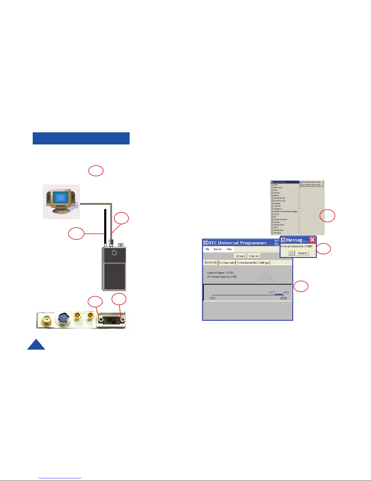
SERIAL PORT OF
COMPUTER
COM1 OR COM2
1 Make sure the video transmitter ON/OFFswitch is set to OFF. The red dot is
OFF.
2 Make sure the transmitter has an antenna installed into the antenna connec-
tor prior to programming.
3 Install the programming cable into the Multi I/O connector on the transmitter.
4 Plug the serial cable of the programming cable
into the COM1 or COM2 port of your computer.
5 Turn the transmitter switch to ON. The green dot
is ON.
6 Select Start, programs, DTC communications on
your computer.
7 The system allows you to select device COM1 or
COM2, depending on which serial port you are
connected to.
8 Follow the instruc-
tions on the DTC
Universal Programming screens to
begin the download
process.
6
7
8
2
3
4
1
5
Page 27
DTC COMMUNICATIONS, INC.
27
5
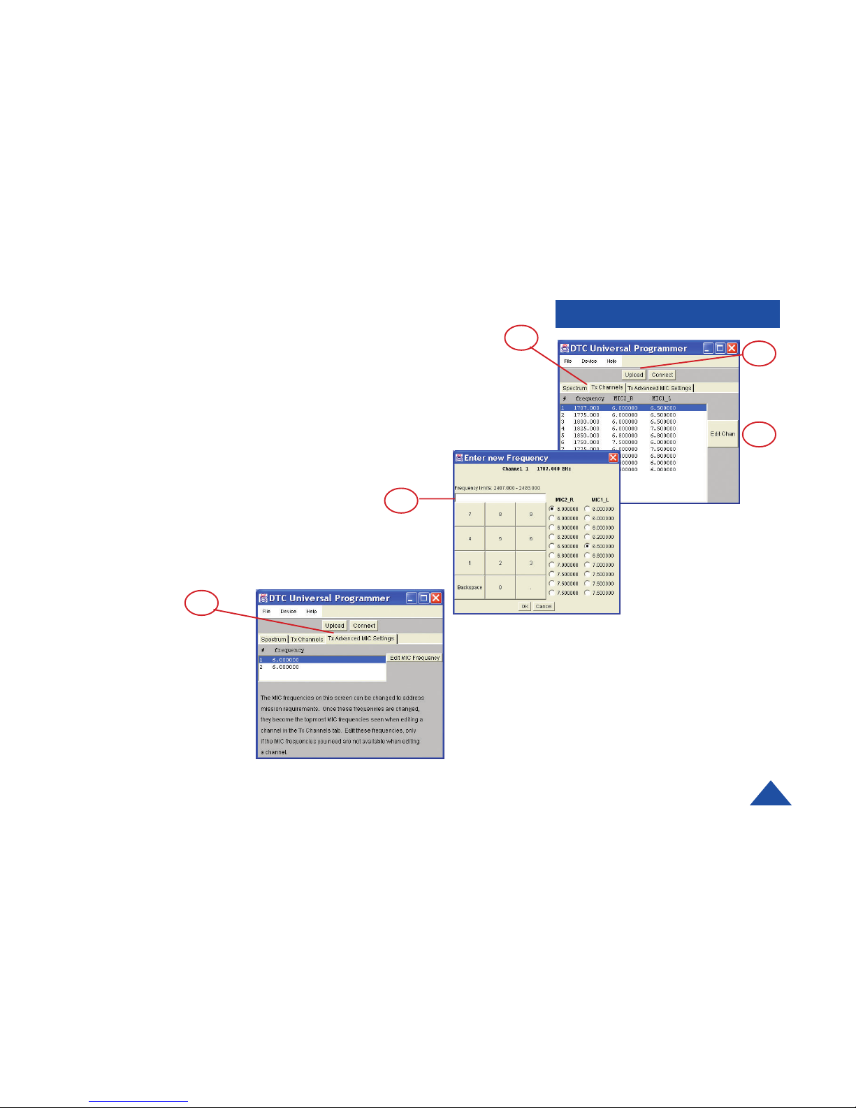
9 Click on the “Tx Channel” tab in the programmer screen.
10 Select a channel and click on the Edit Channel button to change settings.
11 Enter your new frequency and settings.
12 To change any of the MIC-2 or MIC-1 settings, click on the settings provided,
then click OK.
13 Click on the Upload button to upload your new settings to the transmitter.
Your new settings have been installed.
PROGRAMMING
13
9
10
12
11
Page 28

DTC COMMUNICATIONS, INC.
28
APPENDIX A
Using Antennas with the VBS/VBL-250 Video Transmitter
Bodyworn applications:
When the VBS/VBL-250 video transmitter is to be worn on the body, only the DTC
VidiWire antenna system should be used. This antenna has been extensively
tested and found to be safe when used as directed. The antennas used in the
VidiWire system are clearly labeled as to which side of the antenna should be
placed against the body. These directions must be observed to insure safe and
effective operation.
Non-portable applications:
In fixed location applications any suitable antenna may be used. However, to
insure safe operation, it is imperative that proper spacing be maintained between
the radiating surface of the antenna and
any persons body. The required spacing
depends on the RF output power of the transmitter and the gain of the antenna
being used. The chart below shows the correct minimum spacing for antennas
used with the VBS/VBL-250 transmitters. If the gain of the antenna is unknown,
contact the manufacturer of the antenna for this information. To insure that proper
spacing is maintained, locate the transmitter or arrange physical barriers in such
away that people are prevented from approaching too closely.
Page 29

DTC COMMUNICATIONS, INC.
29
APPENDIX A
Minimum Allowable Spacing Between the Antenna and the Human Body
(VBS/VBL-250 Video Tr ansmitter)
0
5
10
15
20
25
30
35
40
0 5 10 15 20 25
Ante nna Ga in (dB)
Minimum Spacing (inches)
Using Antennas with the VBS/VBL-250 Video Transmitter
Page 30

486 Amherst Street • Nashua, New Hampshire 03063 • 603- 880 - 4411 www.dtccom.com
 Loading...