

DTC T-2350 User Manual
DTC COMMUNICATIONS INCORPORATED Draft
T-2350-1Watt
Audio Transmitter
PrPr
PrPr
Pr
oject 25 Digital & Analogoject 25 Digital & Analog
oject 25 Digital & Analogoject 25 Digital & Analog
oject 25 Digital & Analog
Users ManualUsers Manual
Users ManualUsers Manual
Users Manual

How to contact DTC
For operator and troubleshooting
information, customers are encouraged to refer to
the details in this manual. For additional
clarification or instruction, or to order parts,
contact DTC.
Customer Service is available Monday through
Friday between the hours of 9:00 AM and 5:00 PM
EST at:
Tel: 603-880-4411
Fax: 603-880-6965
Website: www.dtccom.com
Email: info@dtccom.com
486 Amherst Street
Nashua, New Hampshire 03063
USA
Copyright Notice
Copyright © 2004
DTC Communications, Inc. All rights
reserved. No part of this document may be
reproduced, transmitted, transcribed, stored in a retrieval system or translated into any
language or computer language, in any form or by
any means, including but not limited to electronic,
magnetic, mechanical, optical, chemical, manual or
otherwise, without the prior written permission of
DTC Communications, Inc.
Disclaimer
The information in the document is subject to change
without notice. DTC makes no representations or
warranties with respect to the contents hereof, and
specifically disclaims any implied warranties of merchantability or fitness for a particular purpose. DTC
reserves the right to revise this publication and to
make changes from time to time in the content hereof
without obligation of DTC to notify any person of such
revision or changes.
Trademarks
Trademarks of DTC Communications, Inc. include:
• DTC
• MiniPIX
®
• DynaPIX
®
Other product names used in this manual are the
properties of their respective owners.
W arranty
DTC warrants its manufactured components against
defects in material and workmanship for a period of
two (2) years, commencing on the date of original
purchase.
Products manufactured by others that are approved
for use with DTC equipment are warranted for the
manufacturer’s warranty period, commencing from
the date of shipment from DTC.
Intellectual Property Rights
Notice
Digital Voice Systems, Inc. (DVSI) claims
certain rights, including patent rights under
US Patents #5,870,405, #5,826,222,
#5,754,974, #5,701,390, #5,715,365,
#5,649,050, #5,630,011, #5,581,656,
#5,517,511, #5,491,772, #5,247,579,
#5,226,084, #5,195,166, and under other US
and foreign patents patents and patents
pending, in IMBE Vocoder technology and
software embedded in this product. Any
use of this technology or software requires
a separate written license grant
from DVSI.
IMBE is a registered trademark of Digital
Voice Systems, Inc.
2
3
NOTE Describes special issues you should be aware
of while using a particular function.
WARNING Calls out situations in which equipment
could be damaged or a process could be incorrectly
implemented, but in which operator safety is not a
factor.
TIP Describes application hints.
Manual Conventions
Table of Contents
Overview............................................................................. 4
Connections ...................................................................... 5
Quick Start Option 1 .......................................................... 6
Quick Start Option 2 .......................................................... 7
miniSD
TM
Card ................................................................. 8-9
Recording to a miniSD
TM
Card ......................................... 10
Trouble Shooting ...............................................................11
Tips ................................................................................... 12
Specifications .................................................................. 13
Programming ..............................................................14-16
Progr amming Options ................................................ 1 7-20
Encryption ......................................................................... 21
Accessories Antennas..................................................... 22
Warranty............................................................................ 23
4
The T-2350 is a synthesized VHF, digital and analog audio transmitter with a
software selectable power output of 1 Watt. The T-2350 has an optional
removable Mini SDTM Card that can record approximately 1 minute of audio in
WAV file format per MB of storage.
The T-2350 has 10 programmable channels. It is designed for body worn
personal protection and evidence gathering missions. Its miniature size and
rugged design insures safe concealment and long lasting performance. The
time to half power with fresh AAA Alkaline batteries is 5 hours. The transmission
is programmable for digital P25 clear, digital P25 encrypted, analog
narrowband, or analog wideband operation. The T-2350 transmission is either
duplexed on the mic/antenna cable (meaning the microphone is the antenna)
or transmitted on a stand-alone noodle antenna, in which case the internal
microphone or remote microphone must be used.
Concerned with the rapid evolution of digital communication technologies and
a need for interoperability, the Association of Public Communications safety
Officials (APCO) developed an open architecture, digital standard for public
safety and government communications systems. Products compliant with
APCO Project 25 standard are interoperable, regardless of the manufacturer.
The National Telecommunications and Information Administration (NTIA) has
adopted the APCO Project 25 interoperability standard, also known as TIA/EIA-
102. The T-2350 is compliant with this standard.
Overview
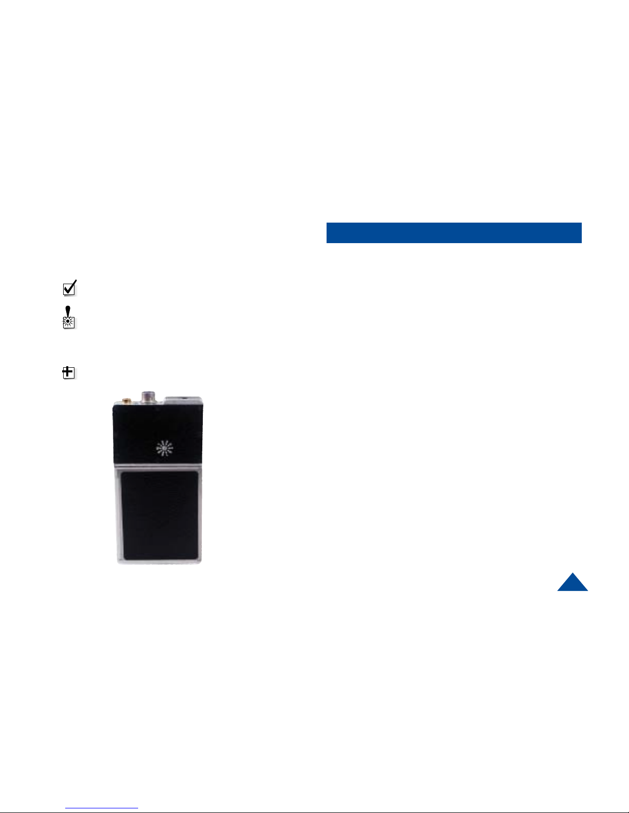
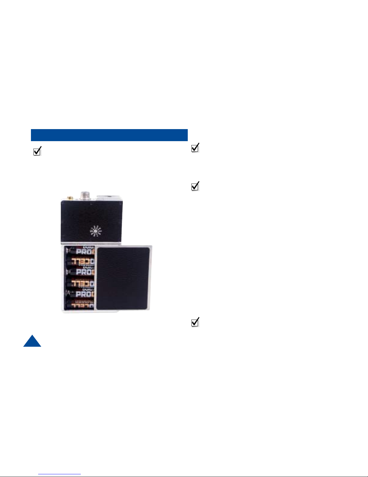
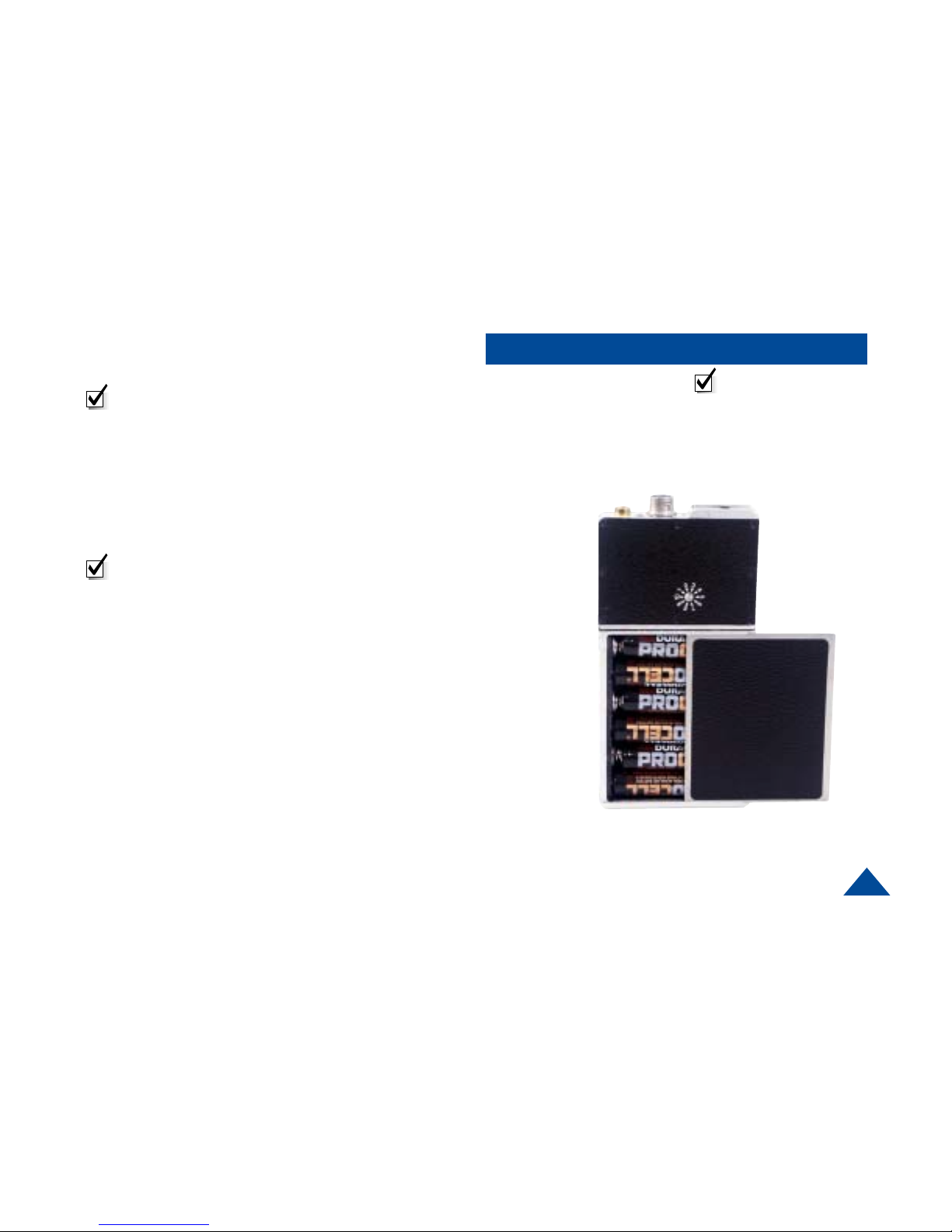
Front of Transmitter
Channel Select
Switch
Internal
Batteries
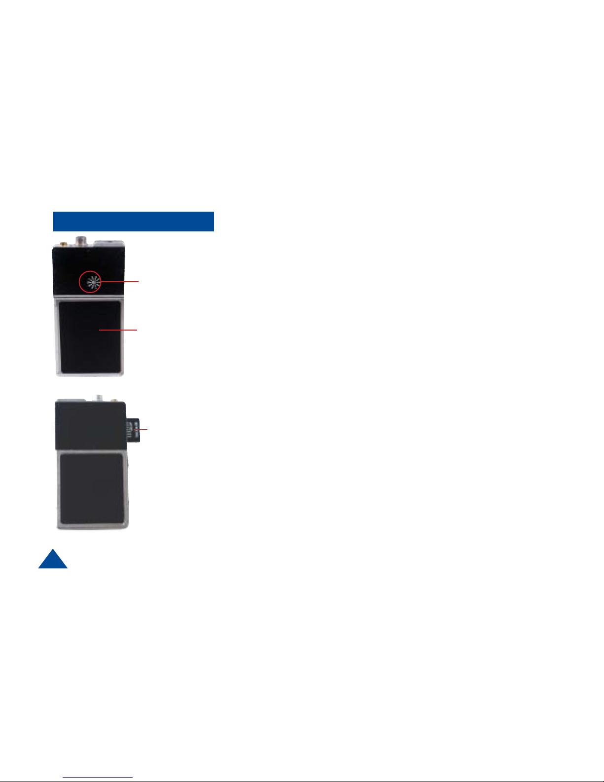
Back of Transmitter
miniSD
TM
Card
5
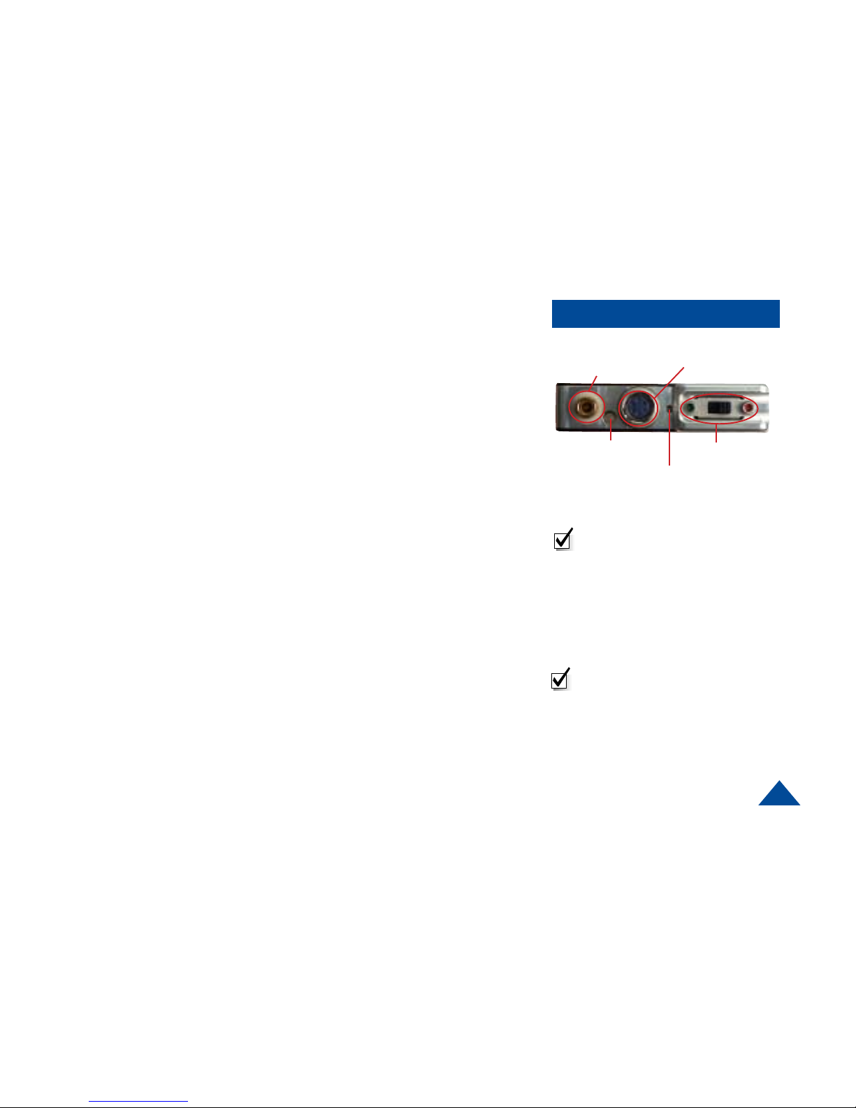
Connections
ANTENNA (Female Lemo Connector)
This connector accepts both the mic/antenna and the noodle antenna.
MULTI-PIN CONNECT OR (Male multi-pin connector)
This connector mates with an external microphone and is used in conjunction
with the noodle antenna. This connector also mates with the programming
cable.
STA TUS LED
Once power is applied (after approximately 3 seconds), the Status LED will turn
on (green), which indicates a successful self-test. The LED will turn off after a
few seconds, and remain off or flash green at 1 second intervals. (See programming section)
ON/OFF SWITCH (Slide Switch: Green dot is ON, Red dot is OFF)
The ON/OFF switch controls the power to the transmitter. The power is supplied
through the internal battery compartment, which holds six AAA batteries. Sliding
the switch to the green dot turns the power ON. Sliding the switch to the red dot
turns the power OFF.
CHANNEL SELECT SWITCH (Rotary Switch)
The channel select switch allows you to change transmit channels and is
located on the front of the transmitter. It is a rotary switch which requires the use
of the supplied screwdriver to turn the switching mechanism. Select a transmit
channel number by turning the rotary switch.
On / Off Switch
Multi Pin Connector
Top View
Internal Microphone
Status LED
Antenna Connector
NOTE: When Cycling power on the
unit, power switch must be left in
the off postion for at least 2
seconds before turning it back on.
NOTE: When using the noodle
antenna, the unit must be programmed to use the alternate
microphone. If no external
microphone is connected, the unit
will automatically use the internal
microphone.
6
QUICK START Option1
Using The Antenna/Mic AssemblyUsing The Antenna/Mic Assembly
Using The Antenna/Mic AssemblyUsing The Antenna/Mic Assembly
Using The Antenna/Mic Assembly
NOTE: The channel being used must be programmed
to use the antenna/mic
1 Install the antenna/mic into the antenna connector
on the transmitter.
NOTE: This is a push-on, push off locking connector.
The connector will rotate 360° in the transmitter
without disconnecting. Use extreme caution when
connecting or removing the mic/antenna.(See
illustration on page 12.)
2 Ensure that the power switch on the transmitter is set
to OFF. (Red dot is OFF).
3 Slide the battery door to the right and install six, fresh
AAA batteries, being careful to observe proper polarity.
Slide the battery door to the left to close the battery
compartment.
4 Using a small screwdriver, turn the recessed rotary
switch located on the front cover, to the desired
channel.
5 Turn the unit on by sliding the switch to the ON
position. (Green dot is ON.)
NOTE: Once power is applied (after approximately 3
seconds), the Status LED will turn on (green), which
indicates a successful self-test. The LED will turn off
after a few seconds.
NOTE: Do not operate
the transmitter without
an antenna installed.
7
QUICK START Option 2
Using A Separate MicrUsing A Separate Micr
Using A Separate MicrUsing A Separate Micr
Using A Separate Micr
ophone with theophone with the
ophone with theophone with the
ophone with the
Noodle AntennaNoodle Antenna
Noodle AntennaNoodle Antenna
Noodle Antenna
NOTE: The channel being used must be programmed
to use the internal mic.
1 Install the 36” remote microphone into the auxiliary
(multi-pin) connector on the transmitter
2 Install the noodle antenna into the antenna connector
on the transmitter. Adjust length to center of operating
frequencies. (See example on Page 22)
NOTE: This is a push-on, push off locking connector.
The connector will rotate 360° in the transmitter without
disconnecting. Use extreme caution when connecting
or removing the noodle antenna.(See illustration on
page 12.)
3 Ensure that the power switch on the transmitter is set
to OFF. (Red dot is OFF).
4 Slide the battery door to the right and install six, fresh
AAA batteries, being careful to observe proper polarity.
Slide the battery door to the left to close the battery
compartment.
5 Using a small screwdriver, turn the recessed rotary
switch located on the front cover to the desired
channel.
6 Turn the unit on by sliding the switch to the ON
position.(Green dot is ON.)
NOTE: Do not operate
the transmitter without
an antenna installed.
8
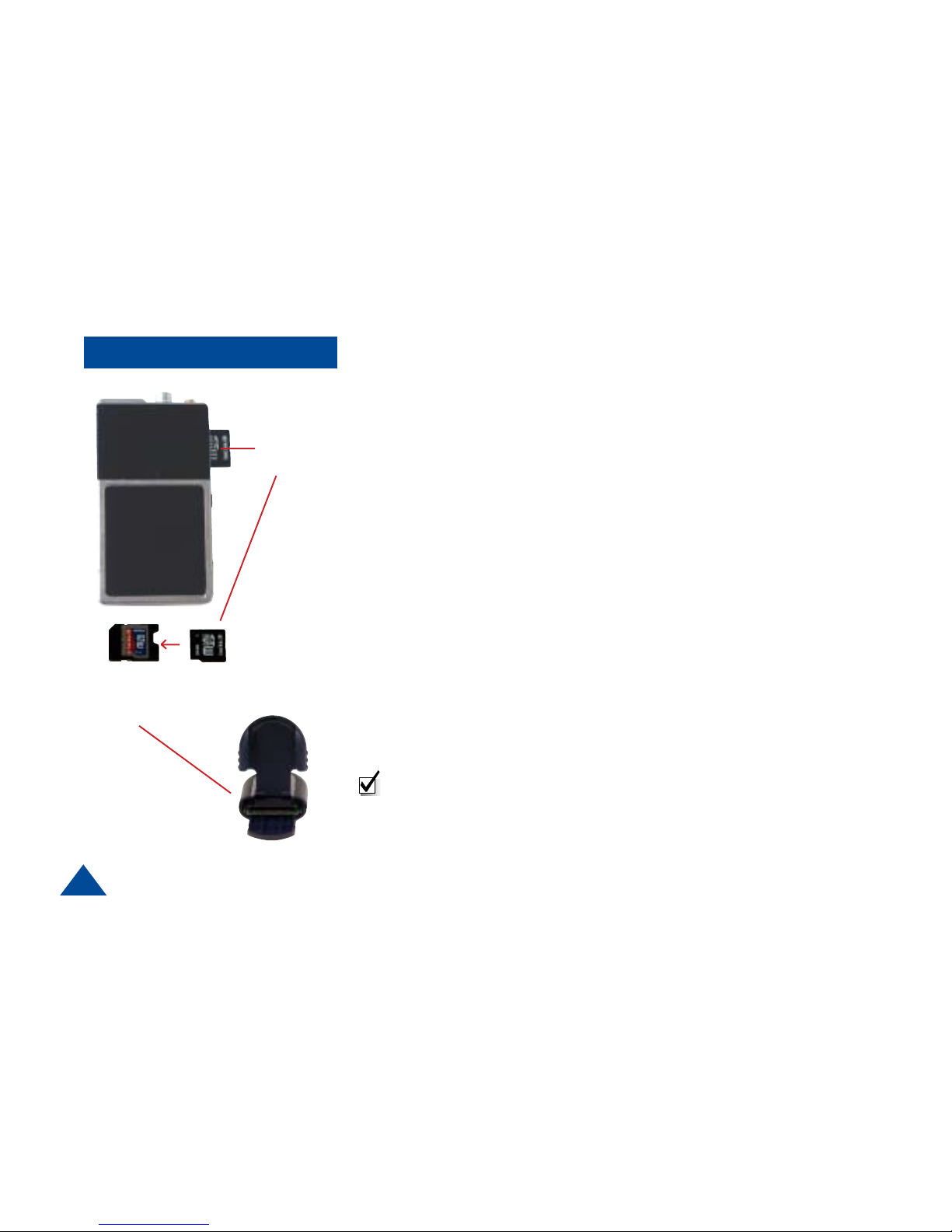
miniSD
TM
Card
miniSD
TM
Card
Adapter (to be
used with Card
Reader)
miniSDTM Card
miniSD
TM
Card
miniSDTM Card
The T-2350 uses an industry-standard miniSD™ card to make audio
recordings. A 512 MB card, an SD to miniSD adapter, and an SD card reader
are provided with a new T-2350. The audio is recorded in a Windows PCM
waveform format (.wav file). Should the need to replace the card arise, they can
be purchased at most major retailers in various densities from 32 Mb to
512 Mb. Higher densities may be available in the future. As an example, a 32Mb
card will provide approximatley 30 minutes of recording time, 64Mb wil provide
about 60 minutes, etc. The 512 Mb card included with the transmitter will
provide well over 8 hours of recording time. Generally speaking, 1 MB of
memory will provide about 1 minute of recording.
Every new miniSD™ must be properly formatted before it can be used.
Formatting is a simple process that can be done on almost any Microsoft
Windows equipped PC, Laptop, Notebook, and some hand-held PCs. Typically,
this will only need to be done once on each card.
Installing miniSD
TM
Card
The miniSD™ card slot is accessed by sliding the side panel down (Figure 2).
The Card is inserted with the gold tabs facing the same side as the Channel
Switch. When installed, a red LED will be illuminated indicating that the card
should not be removed due to file management activity. Wait until the red LED
is OFF before removing the card by gently pushing in until it releases.
SD Card
Reader
NOTE: Never insert or remove the card while power is ON.
 Loading...