

Page 1
Resource Identifier 100249
Revision: 1.0
AEON Family User Guide
Commercial in Confidence
DTC – Solent
Fusion 2
1100 Parkway
Solent Business Park
Whiteley
Hampshire
PO15 7AB
United Kingdom
+44 (0)1489 566 750
Page 2

AEON Family User Guide
Commercial in Confidence
Video, Broadcast
100249
Revision: 1.0
Commercial in Confidence
Page 0-1
0. Preface
0.1 About this Document
This document contains relevant information required to identify, install and control the equipment or
system.
Since the available functions can be licensed and depend on the specific implementation, not all the
functions and or applications contained in this document may be relevant or applicable to the system you
will be working with.
The actual presentation may differ from those in this document due to hardware or software changes.
0.2 Who Should Read this Publication
This document is meant for anyone interested in how the system can best be used, but it is of most benefit
to:
Operators who are in charge of the daily operation of the equipment.
Installers who are responsible for the pre-installation, on-site installation and configuration of the
system in the end-user environment.
Maintainers who are responsible for maintaining the equipment or system.
0.3 Assumed Knowledge
Throughout this book it is assumed that the reader has a thorough knowledge of:
Basic personal computer operations
Basic radio frequency (RF) principles
0.4 Notice about Specifications
While DTC makes every attempt to maintain the accuracy of the information contained in its product
manuals, the information is subject to change without notice. Performance specifications included in this
manual are design-centre specifications and are included for customer guidance and to facilitate system
installation. Actual operating performance may vary.
0.5 Notice about this Guide
The product described in this manual is subject to continuous development and improvement. All
particulars of the product and its use (including the information and particulars in this guide) are given by
DTC in good faith. However, it is acknowledged there may be errors or omissions in this guide.
Page 3
AEON Family User Guide
Commercial in Confidence
Video, Broadcast
100249
Revision: 1.0
Commercial in Confidence
Page 0-2
0.6 Typographic Conventions
This document uses these typographic conventions to identify text that has a special meaning:
Typographic Convention
Example
TEXT in non-bold capitals represents a specific key press on the
console keyboard or hardware panel.
ESC, F1, SHIFT
The + sign means “hold down the first key while pressing the
second key”.
Press CTRL+C to abort
<Text> Serves as a placeholder for variable text that you will
replace as appropriate to its context.
Use the filename
<system_name>.sys for…
Text in bold emphasises a new word or term of significance.
We call this a protocol and its
function is…
Text in italics can represent a link to place in the existing document
(often these are hyperlinks) or a reference to another document.
Refer to Section 0.6, Typographic
Conventions.
Successive menu selections are shown using arrows to indicate a
sub-menu. In this example this would mean:
Select the Insert menu, then select picture, then select from file.
Insert>picture>from file
0.7 Symbols
This document uses these symbols to highlight important information:
WARNING: A written notice given to a reader when a situation might result in personal injury or loss of life.
CAUTION: A written notice given when a situation might result in loss of data, damage to or destruction of
equipment or systems.
Note: A written notice given to draw the reader’s attention to something or to supply additional information.
0.8 Trademarks
All trademarks or registered trademarks that appear in this document are the property of their respective
owners.
© 2018 Domo Tactical Communications (DTC) Limited
Domo Tactical Communications (DTC) Limited owns the copyright of this document which is supplied in
confidence and must not be used for any purpose other than for which it is supplied and must not be
reproduced without permission in writing from the owners.
Page 4
AEON Family User Guide
Commercial in Confidence
Video, Broadcast
100249
Revision: 1.0
Commercial in Confidence
Page 0-3
0.9 Related Documents
You may also need to refer to:
Document
Source
Solo Concept Guide
DTC
IP Concept Guide
DTC
NETNode Phase 5 Software User Guide
DTC
0.10 Document History
This document was written and produced by the DTC Technical Publications Team.
This is a change controlled document. Each main page of this document displays a revision number at the
bottom left corner of the page. The revision and date of issue are also indicated in the table below.
Changes to any page will raise the revision status of the whole document.
Revision
Date
Authors
Summary of Changes
1.0
06/02/2018
IR
First release
Page 5

AEON Family User Guide
Commercial in Confidence
Video, Broadcast
100249
Revision: 1.0
Commercial in Confidence
Page 0-4
Contents
0. Preface ...................................................................................................... 0-1
0.1 About this Document .................................................................................................................... 0-1
0.2 Who Should Read this Publication ................................................................................................ 0-1
0.3 Assumed Knowledge ..................................................................................................................... 0-1
0.4 Notice about Specifications .......................................................................................................... 0-1
0.5 Notice about this Guide ................................................................................................................ 0-1
0.6 Typographic Conventions .............................................................................................................. 0-2
0.7 Symbols ........................................................................................................................................ 0-2
0.8 Trademarks ................................................................................................................................... 0-2
0.9 Related Documents ....................................................................................................................... 0-3
0.10 Document History ...................................................................................................................... 0-3
1. Product Overview ...................................................................................... 1-1
1.1 Product Family .............................................................................................................................. 1-1
1.2 AEON Transmitter ......................................................................................................................... 1-1
1.3 AEON Decoder ............................................................................................................................... 1-3
1.4 AEON Encoder ............................................................................................................................... 1-4
2. Product Package ....................................................................................... 2-5
2.1 Overview ....................................................................................................................................... 2-5
2.2 AEON Transmitter Parts List ......................................................................................................... 2-5
2.3 AEON Decoder Parts List ............................................................................................................... 2-5
2.4 AEON Encoder Parts List ............................................................................................................... 2-6
2.5 Accessory Options ......................................................................................................................... 2-6
2.6 AEON Transmitter Licensing Options ............................................................................................ 2-7
2.7 AEON Transmitter Variants ........................................................................................................... 2-7
2.8 Labelling ....................................................................................................................................... 2-8
3. Connections, Controls and Indicators ........................................................ 3-9
3.1 Introduction .................................................................................................................................. 3-9
3.2 AEON Transmitter ......................................................................................................................... 3-9
3.3 AEON Rack Decoder/Encoder ....................................................................................................... 3-15
4. Getting Started ....................................................................................... 4-17
4.1 Power .......................................................................................................................................... 4-17
4.2 Access the USB Stick .................................................................................................................. 4-17
4.3 Using Node Finder ....................................................................................................................... 4-18
4.4 AEON Transmitter Web Browser Control ...................................................................................... 4-20
4.5 Web Browser Options .................................................................................................................. 4-21
4.6 LCD/OLED Display Control ........................................................................................................... 4-21
5. AEON Transmitter Web Browser Operation ............................................... 5-22
5.1 Introduction ................................................................................................................................ 5-22
5.2 Unit Status>Overview Tab .......................................................................................................... 5-22
5.3 Unit Status>Service>Status ...................................................................................................... 5-23
5.4 Unit Status>SDI/SFP Tab ............................................................................................................ 5-23
5.5 The Apply, Save and Refresh Buttons ......................................................................................... 5-24
5.6 Configuration>Global Tab .......................................................................................................... 5-24
5.7 Configuration>Preset>Unit ........................................................................................................ 5-28
5.8 Configuration>Preset>Encoder Tab ........................................................................................... 5-30
5.9 Configuration>Preset>Audio Tab ............................................................................................... 5-31
Page 6

AEON Family User Guide
Commercial in Confidence
Video, Broadcast
100249
Revision: 1.0
Commercial in Confidence
Page 0-5
5.10 Configuration>Preset>Data Tab ............................................................................................ 5-31
5.11 Configuration>Preset>Streamer ............................................................................................ 5-32
5.12 Configuration>Preset>Modulator Tab .................................................................................... 5-34
5.13 Engineering>Information Tab ................................................................................................. 5-36
5.14 Engineering>Calibration Tab .................................................................................................. 5-37
5.15 Engineering>Uploads ............................................................................................................. 5-37
6. AEON Transmitter – SDR Dual Encoder .................................................... 6-38
6.1 Introduction ................................................................................................................................ 6-38
6.2 Unit Status>Service>Status Tab ................................................................................................ 6-39
6.3 Unit Status>Service>PTZ Tab .................................................................................................... 6-40
6.4 Configuration>Preset>Encoder Tab ........................................................................................... 6-41
6.5 Configuration>Preset>Audio Tab ............................................................................................... 6-46
6.6 Configuration>Preset>Data Tab ................................................................................................ 6-48
6.7 Configuration>Preset>Streamer Tab ......................................................................................... 6-50
7. AEON-MESH Web Browser Operation ........................................................ 7-54
7.1 Introduction ................................................................................................................................ 7-54
7.2 AEON-MESH with AEON Encoder ................................................................................................. 7-55
7.3 AEON-MESH with SDR Dual Encoder ........................................................................................... 7-56
8. AEON Transmitter LCD Display Operation ................................................ 8-58
8.1 Overview ..................................................................................................................................... 8-58
8.2 Icons and Controls ...................................................................................................................... 8-58
8.3 Navigating the Menu .................................................................................................................. 8-59
9. AEON Decoder/Encoder Operation ............................................................ 9-60
9.1 Introduction ................................................................................................................................ 9-60
9.2 OLED Display ............................................................................................................................... 9-60
9.3 Configurable Values ................................................................................................................... 9-61
10. Example Applications ........................................................................ 10-62
10.1 Single AEON 4K HEVC Encoder .............................................................................................. 10-62
10.2 MESH Application .................................................................................................................. 10-65
11. Appendix A – Reference Material ....................................................... 11-68
11.1 How to Configure a PC IP Address ......................................................................................... 11-68
11.2 AEON Transmitter Pinouts ..................................................................................................... 11-69
11.3 AEON Decoder/Encoder Pinouts ............................................................................................. 11-71
12. Appendix B – Getting Technical Support ............................................ 12-72
12.1 Documentation and Software ................................................................................................ 12-72
12.2 Repairs .................................................................................................................................. 12-72
12.3 Contact Technical Support .................................................................................................... 12-72
12.1 Using the DTC RMA Service ................................................................................................... 12-72
13. Appendix C – Cautions and Approvals ............................................... 13-74
13.1 Cautions and Warnings ......................................................................................................... 13-74
13.2 EMC/Safety and Radio Approvals .......................................................................................... 13-75
13.3 CE Marking............................................................................................................................ 13-75
14. Appendix D – Care and Maintenance ................................................. 14-76
Page 7

AEON Family User Guide
Commercial in Confidence
Video, Broadcast
100249
Revision: 1.0
Commercial in Confidence
Page 0-6
14.1 Caring for your Equipment .................................................................................................... 14-76
14.2 Charging ............................................................................................................................... 14-76
14.3 Working with Lithium Batteries ............................................................................................. 14-76
14.4 Cleaning ................................................................................................................................ 14-77
14.5 Storage .................................................................................................................................. 14-77
15. Appendix E – Glossary........................................................................ 15-78
Page 8
AEON Family User Guide
Commercial in Confidence
Video, Broadcast
100249
Revision: 1.0
Commercial in Confidence
Page 1-1
1. Product Overview
1.1 Product Family
The subject equipment of this user guide is:
Product Code
Product Description
AEON-TX
AEON HEVC Transmitter
AEON-ENC
AEON 4K Encoder
AEON-DEC
AEON 4K Decoder
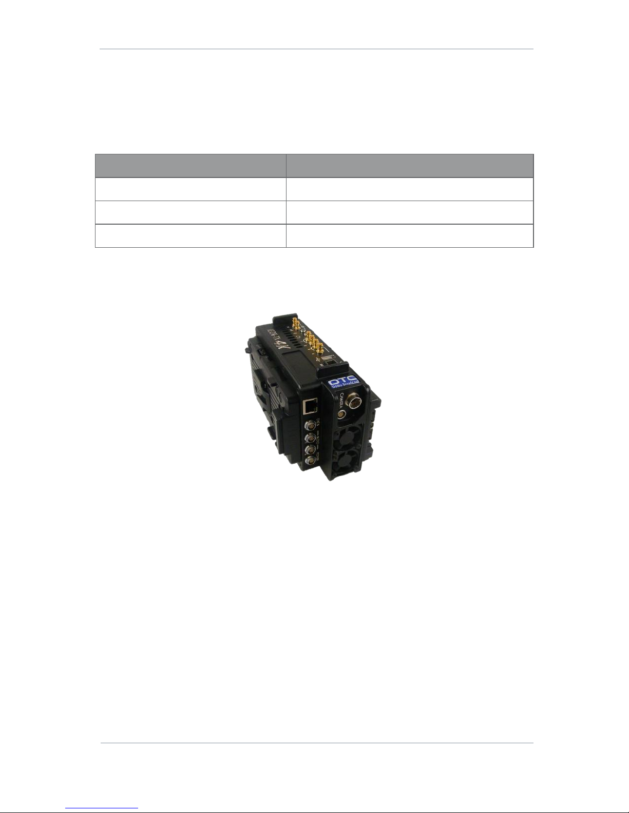
1.2 AEON Transmitter
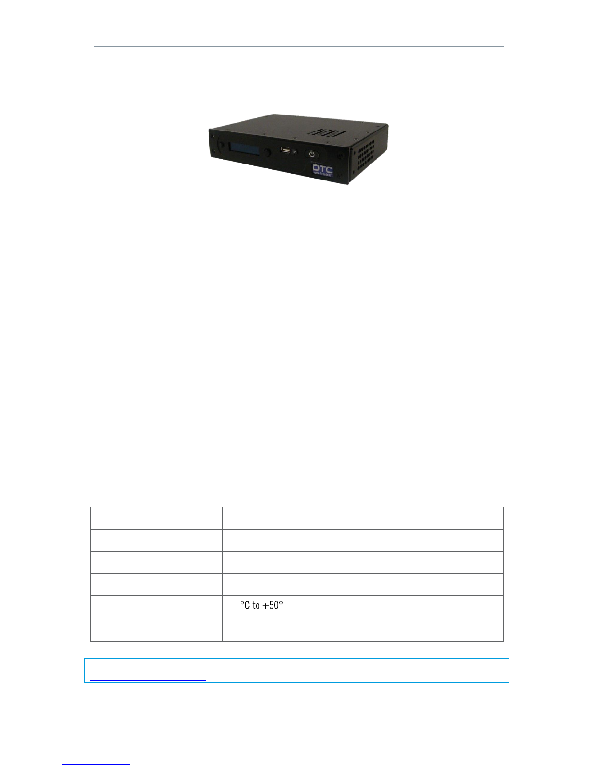
Figure 1-1 AEON Transmitter
Description
A compact and feature-rich COFDM digital video transmitter, specifically designed for high quality wireless
link applications. With proven Domo COFDM and next generation HEVC encoder technology at its core
enabling Ultra High Definition images the small size and actively cooled enclosure give maximum
operational performance. Designed to offer future proof connectivity, the unit supports native 12G-SDI, dual
6G-SDI, quad 3G-SDI, as well as SFP+ expansion. Two true balanced audio inputs are included with
phantom power. The transmitter has an integrated control panel with sunlight-readable LCD display
covering all major functions and has 16 user-defined presets, as well as IP based control.
The HEVC codec used in AEON products offers a step change in compression efficiency over H.264 systems,
whilst maintaining low end to end latency suitable for live events.
Page 9
AEON Family User Guide
Commercial in Confidence
Video, Broadcast
100249
Revision: 1.0
Commercial in Confidence
Page 1-2
Features
Ultra-low latency HEVC SD, HD and 4K encoding
Video formats up to 2160p60, 10-bit and 4:2:2 chroma sampling, future HDR support
Industry standard DVB-T modulation for interoperability with existing systems
Domo Broadcast UMVL modulation for enhanced high frequency/high speed performance
Controlled via IP or integrated sunlight-readable LCD display
Designed for sports & events coverage, newsgathering and wireless studio camera applications
Integrated return channels for bi-direction IP connectivity and low bandwidth telemetry
Scalable return channel for talk-back to camera control to return video
Low power consumption and active cooling for extended field performance
Basic Specifications
Dimensions
L 190mm (170mm excluding connectors)
W 115mm, (105mm excluding connectors)
D 55mm (without battery plates) or
D 89mm (with V-Lock plates) or
D 82mm (with Anton Bauer plates)
Weight
1600g
DC Input
9.2 to 17.8V reverse polarity protected
Power consumption
Typically 30.0W @ 100mW RF power and 4K video
Temperature range
-10
Humidity
Less than 85% non-condensing
Note: Detailed technical specifications are given in the product datasheet. Please see
http://www.domotactical.com/.
Page 10
AEON Family User Guide
Commercial in Confidence
Video, Broadcast
100249
Revision: 1.0
Commercial in Confidence
Page 1-3
1.3 AEON Decoder
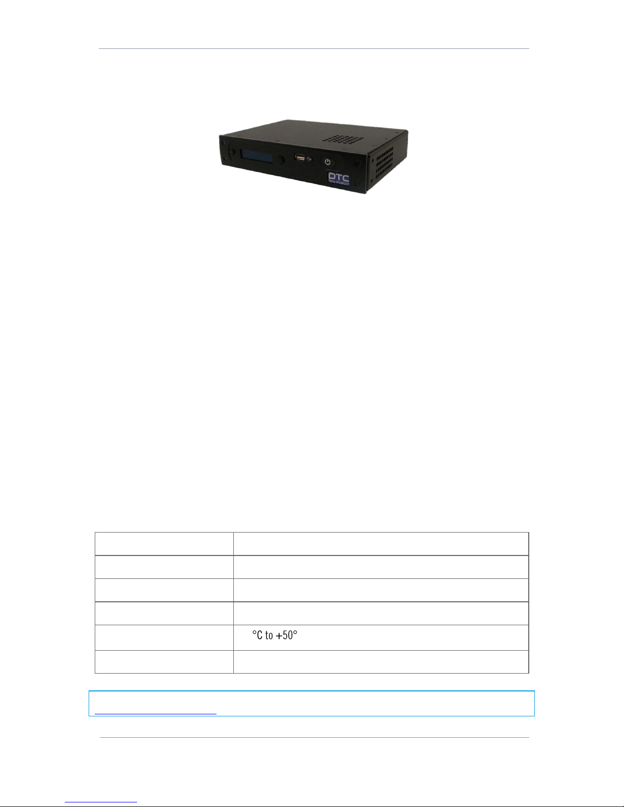
Figure 1-2 AEON Decoder
Description
The AEON HEVC Rack Decoder provides low latency HEVC Ultra High Definition decoding from ASI/IP input.
Ideal for adding decode support for the AEON Transmitter to existing receiver systems. Each decoder can
support single 4K or up to two HD streams via quad 3G-SDI outputs, and has two stereo balanced audio
outputs available. The decoder has an integrated control panel with sunlight-readable OLED display
covering all major functions, as well as IP based control.
The HEVC codec used in AEON products offers a step change in compression efficiency over H.264 systems,
whilst maintaining low end to end latency suitable for live events.
Features
Ultra-low latency HEVC SD, HD and 4K decoding with Tri-level sync genlock
Video formats up to 2160p60, 10-bit and 4:2:2 Chroma sampling, future HDR support
Controlled via IP or integrated sunlight-readable OLED display
Designed for sports & events coverage, newsgathering and wireless studio camera applications
Scalable decoding platform supporting single 4K or two HD services
Low power consumption and active cooling for extended field performance
Compact 1/2 1RU rack form factor
Basic Specifications
Dimensions
180mm (L), 222mm (W), 43mm (W)
Weight
1155g
DC Input
12V to 17V
Power consumption
Typically 16.0W with 4K decoding
Temperature range
-10
Humidity
Less than 85% non-condensing
Note: Detailed technical specifications are given in the product datasheet. Please see
http://www.domotactical.com/.
Page 11
AEON Family User Guide
Commercial in Confidence
Video, Broadcast
100249
Revision: 1.0
Commercial in Confidence
Page 1-4
1.4 AEON Encoder
Figure 1-3 AEON Encoder
Description
The AEON HEVC Rack Encoder provides low latency HEVC Ultra High Definition encoding to ASI/IP output.
Ideal for adding 4K, multi-channel, HEVC support to existing RF/IP systems. Each encoder can support
single 4K or up to 4 HD streams via quad 3G-SDI inputs, and has two stereo balanced audio inputs
available with phantom power. The encoder has an integrated control panel with sunlight-readable OLED
display covering all major functions, as well as IP based control.
The HEVC codec used in AEON products offers a step change in compression efficiency over H.264 systems,
whilst maintaining low end to end latency suitable for live events.
Features
Ultra-low latency HEVC SD, HD and 4K encoding
Video formats up to 2160p60, 10-bit and 4:2:2 Chroma sampling, future HDR support
Controlled via IP or integrated sunlight-readable OLED display
Designed for sports & events coverage, newsgathering and wireless studio camera applications
Scalable encoding platform supporting single 4K or four HD services
Low power consumption and active cooling for extended field performance
Compact 1/2 1RU rack form factor
Basic Specifications
Dimensions
L 180mm, W 222mm, H 43mm
Weight
1155g
DC Input
12V to 17V
Power consumption
Typically 16.0W with 4K encoding
Temperature range
-10
Humidity
Less than 85% non-condensing
Note: Detailed technical specifications are given in the product datasheet. Please see
http://www.domotactical.com/.
Page 12
AEON Family User Guide
Commercial in Confidence
Video, Broadcast
100249
Revision: 1.0
Commercial in Confidence
Page 2-5
2. Product Package
2.1 Overview
Carefully open the packaging and remove the device. Verify that all the components have been included in
the package as shown in the packing list. Inspect the unit for shipping damage.
Note: If you don’t have all the parts or you are not happy with the condition of your delivered product, please
call DTC and we’ll get this solved for you. See Section 12.
Retain the packing list and all the packing materials for storage. The codes mean:
CA – Cable Assembly
SA – Sub Assembly
AP – Assembly Part
The codes are useful for identification and if you need to order a new part at some time.
2.2 AEON Transmitter Parts List
Part Number
Description
AEON-TX
AEON HEVC Transmitter
CA0579
XLR audio input cable
CA3348
AEON-TX UHD BNC to R/A HD-BNC 1855A 250mm cable
SA4075
AEON HEVC support USB stick consisting:
Node Finder application
AEON Family User Guide
Table 2-1 Parts in the AEON-TX Package
2.3 AEON Decoder Parts List
Part Number
Description
AEON-DEC
AEON HEVC Rack Decoder
CA0512
XLR audio output cable
CA0649
XLR 12V 6.67A 80W desktop PSU
SA4075
AEON HEVC support USB stick consisting:
Node Finder application
AEON Family User Guide
Table 2-2 Parts in the AEON-DEC Package
Page 13
AEON Family User Guide
Commercial in Confidence
Video, Broadcast
100249
Revision: 1.0
Commercial in Confidence
Page 2-6
2.4 AEON Encoder Parts List
Part Number
Description
AEON-ENC
AEON HEVC Rack Encoder
CA0579
XLR audio input cable
CA0649
XLR 12V 6.67A 80W desktop PSU
SA4075
AEON HEVC support USB stick consisting:
Node Finder application
AEON Family User Guide
Table 2-3 Parts in the AEON-ENC Package
2.5 Accessory Options
If you have purchased these options, they will also be in the package.
Part Number
Description
PRORXD-1RU
Professional Receiver 1RU
PRORXD-2RU
Professional Receiver 2RU
SOL8KF-043
Three button key fob (433.05-434.79MHz)
CA0340
RS-232 data input cable
CA3421
0B Lemo 15V 6.0A 90W desktop PSU
Table 2-4 AEON Accessory Options
Page 14
AEON Family User Guide
Commercial in Confidence
Video, Broadcast
100249
Revision: 1.0
Commercial in Confidence
Page 2-7
2.6 AEON Transmitter Licensing Options
The device licensing is viewable from the web browser software control application.
Part Number
Description
Silver (included)
DVB-T, Ultra Mobile Video Link (UMVL), Single HD Encoder
Gold
Silver plus DVB-T2 (future development)
Platinum
Gold plus Single 4K and Quad HD Encoder
AEON-TX-HDUP
Additional transmitter HD license
AES128TX
AES128 encryption
AES256TX
AES256 encryption
Table 2-5 AEON-TX Licensing Options
2.7 AEON Transmitter Variants
Product Code
This part number will be on the AEON-TX label. This will identify which variant has been delivered to you.
Part Number
Product Description
AEON-TX-AB-198750D-044
AEON-TX 1.98-2.70GHz, 6.40-7.50GHz, 410-480MHz telemetry, AB-Mount
AEON-TX-V-198750D-044
AEON-TX 1.98-2.70GHz, 6.40-7.50GHz, 410-480MHz telemetry, V-Mount
AEON-TX-AB-440500-043
AEON-TX 4.40-5.00GHz, 433.05-434.79MHz telemetry, AB-Mount
AEON-TX-V-440500-043
AEON-TX 4.40-5.00GHz, 433.05-434.79MHz telemetry, V-Mount
Table 2-6 AEON-TX Variants
Product Code Frequency
Although most of the product code is self-explanatory, it may be useful to explain the differences in the
frequency variants.
Where the COFDM frequency is dual band, the primary frequency will transmit on ports Tx/RX A and Tx/Rx B
and the secondary frequency band will transmit on Tx C only. For example:
198750 = 1.98-2.70GHz (Tx/RX A and Tx/Rx B) and 6.40-7.50GHz (Tx C only)
Note: This will be configured using the web browser control application, see Section 5.12.
Page 15
AEON Family User Guide
Commercial in Confidence
Video, Broadcast
100249
Revision: 1.0
Commercial in Confidence
Page 2-8
2.8 Labelling
This topic contains information covering labels and markings on your device. The legend and location of
each label or marking will be identified and explained for safety or maintenance significant information.
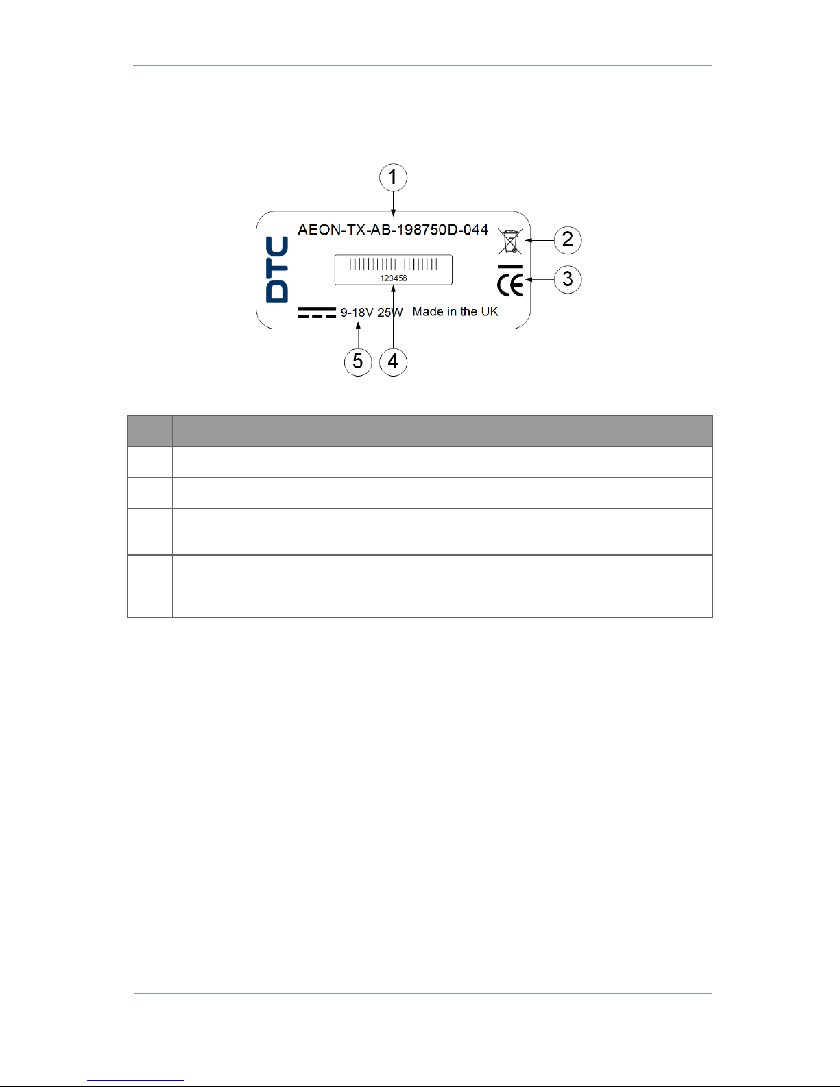
Figure 2-1 AEON Label
No
Description
1
Product code – this will include the product name, battery mount and variant.
2
Indicates that the unit should be disposed of in accordance with the WEEE Directive.
3
The CE marking certifies that a product has met EU consumer safety, health and environmental
requirements.
4
Barcoded six digit serial number. This may be required during a support call.
5
Power requirements.
Table 2-7 AEON Label Key
Page 16
AEON Family User Guide
Commercial in Confidence
Video, Broadcast
100249
Revision: 1.0
Commercial in Confidence
Page 3-9
3. Connections, Controls and Indicators
3.1 Introduction
This section will help you identify all the connections and interfaces to help you install and control the AEON
Transmitter, Decoder or Encoder.
3.2 AEON Transmitter
The AEON-TX has several facets which have been given nominal titles; Top Panel, Bottom Panel, Left Panel
(LCD), Right Panel, Camera Mount Plate and Battery Mount Plate.
Top Panel
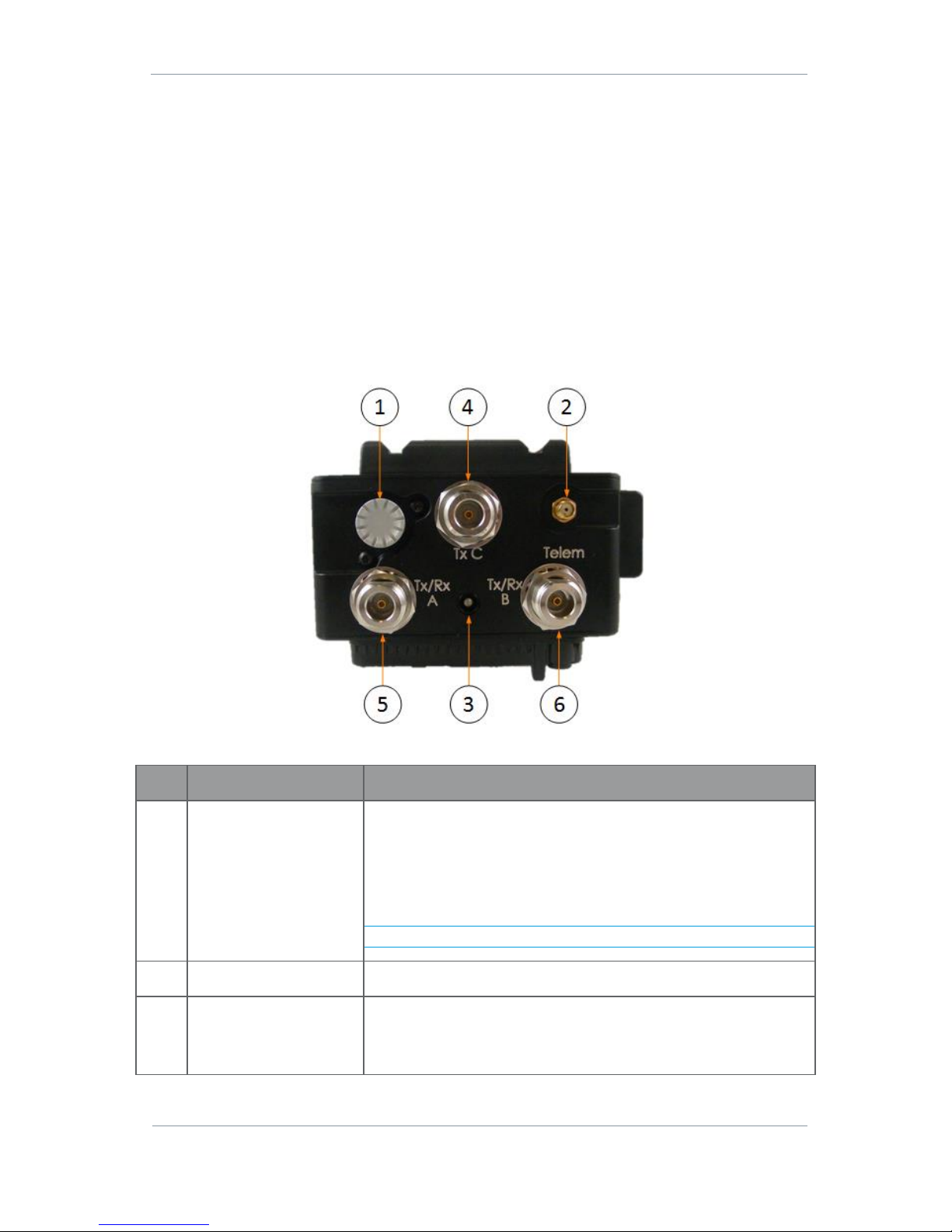
Figure 3-1 AEON-TX Top Panel
No
Item
Purpose
1
LCD display control
button
Button can be rotated and pushed up, down, left and right to navigate
the LCD display menu.
Left/right moves through the menu levels
Up/down changes the menu selection
Rotate to change a value
Short push to enter a value.
Note: For full details of LCD display operation, refer to Section 8.
2
SMA socket
Telemetry antenna connector.
3
LED indicator
Power/RF Status:
Red = unit has booted up, no RF power
Green = RF output on (TX mode) or in link (Mesh mode)
Page 17

AEON Family User Guide
Commercial in Confidence
Video, Broadcast
100249
Revision: 1.0
Commercial in Confidence
Page 3-10
No
Item
Purpose
4
N-type socket
COFDM TX only antenna C connector. Read note below.
This port transmits in the secondary frequency band. See Section 2.7.
When transmitting in this band, port C is the only TX output.
5
N-type socket
COFDM TX/RX antenna A connector. Read note below.
This port transmits in the primary frequency band. See Section 2.7.
When transmitting in this band and configured as a SOL-TX, this will
be a selectable TX only port. When configured as a MESH, it can
become a TX/RX port.
6
N-type socket
COFDM TX/RX antenna B connector. Read note below.
This port transmits in the primary frequency band, 1.98–2.7GHz or
4.4–5GHz or 5.5–6GHz.
When transmitting in this band and configured as a SOL-TX, this will
be a selectable TX only port. When configured as a MESH, it can
become a TX/RX port.
Table 3-1 AEON-TX Front Panel Key
Note: The transmit port selection is achieved by selecting the modulation frequency in the web browser
control application, see Section 5.12.
Page 18
AEON Family User Guide
Commercial in Confidence
Video, Broadcast
100249
Revision: 1.0
Commercial in Confidence
Page 3-11
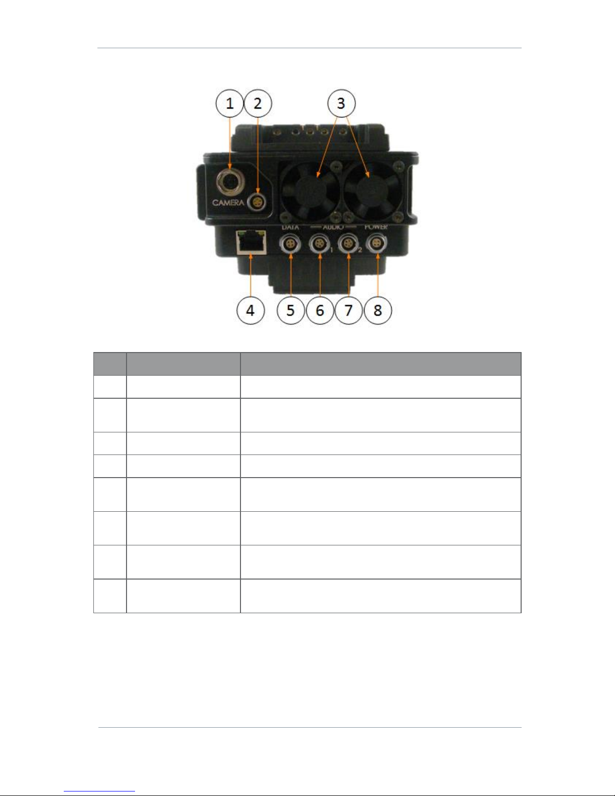
Bottom Panel
Figure 3-2 AEON-TX Bottom Panel
No
Item
Purpose
1
Hirose 10-way jack (pins)
Data and power to the camera. See Section 11.2 for pinout.
2
Lemo 0B, single G key, 5way jack (sockets)
Tally light control. See Section 11.2 for pinout.
3
Fans
Provides cooling for internal components. Take care not to obstruct.
4
RJ45 jack
Ethernet connection for IP control and video streaming.
5
Lemo 0B, 4-way jack
(sockets)
RS-232 data interface. See Section 11.2 for pinout.
6
Lemo 0B, twin A key, 5way jack (sockets)
Channel 1 balanced left and right audio input with switchable 48V
phantom power. See Section 11.2 for pinout.
7
Lemo 0B, twin A key, 5way jack (sockets)
Channel 2 balanced left and right audio input with switchable 48V
phantom power. See Section 11.2 for pinout.
8
Lemo 0B, single G key, 4way jack (sockets)
12V DC input (9.2V – 17.8V). See Section 11.2 for pinout.
Table 3-2 AEON-TX Bottom Panel Key
Page 19
AEON Family User Guide
Commercial in Confidence
Video, Broadcast
100249
Revision: 1.0
Commercial in Confidence
Page 3-12
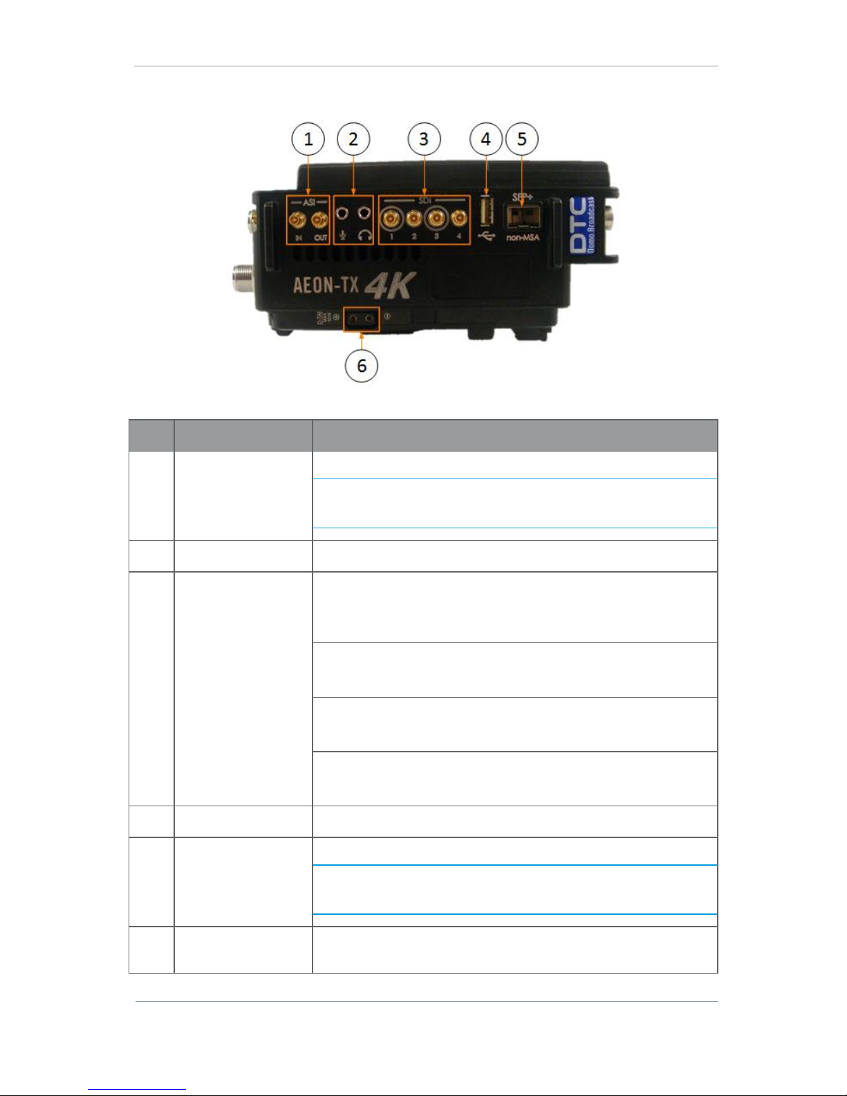
Right Panel
Figure 3-3 AEON-TX Right Panel
No
Item
Purpose
1
High density BNC
socket x 2
ASI video In and Out.
Note: ASI IN can be set up as an SDI input when the AEON Transmitter
is configured as an SDR Dual Encoder in the web browser application
(see Section 6) as long as the ASI IN is not being used for Remux.
2
3.5mm jack socket x 2
Microphone and headphone audio for talkback.
3
High density BNC
socket x 4
SDI video input 1. Supports 12G-SDI (single input), 6G-SDI (dual input)
or 3G-SDI (quad input).
The supplied CA3348 cables will adapt the HD-BNC connectors to BNC.
SDI video input 2. Supports 3G-SDI (quad input).
The supplied CA3348 cables will adapt the HD-BNC connectors to BNC.
SDI video input 3. Supports 6G-SDI (dual input) or 3G-SDI (quad input).
The supplied CA3348 cables will adapt the HD-BNC connectors to BNC.
SDI video input 4. Supports 3G-SDI (quad input).
The supplied CA3348 cables will adapt the HD-BNC connectors to BNC.
4
USB jack
USB host or peripheral device connection.
5
SFP+ jack
Can be used for a single 12G-SDI or dual 6G-SDI input.
Note: This will override SDI input 1 when using 12G-SDI. One channel
may be used in conjunction with SDI input 1 or 3 when using 6G-SDI as
a dual input.
6
D-tap supply
This terminal can tap up to 50W of power from the battery for auxiliary
use.
Table 3-3 AEON-TX Right Panel Key
Page 20
AEON Family User Guide
Commercial in Confidence
Video, Broadcast
100249
Revision: 1.0
Commercial in Confidence
Page 3-13
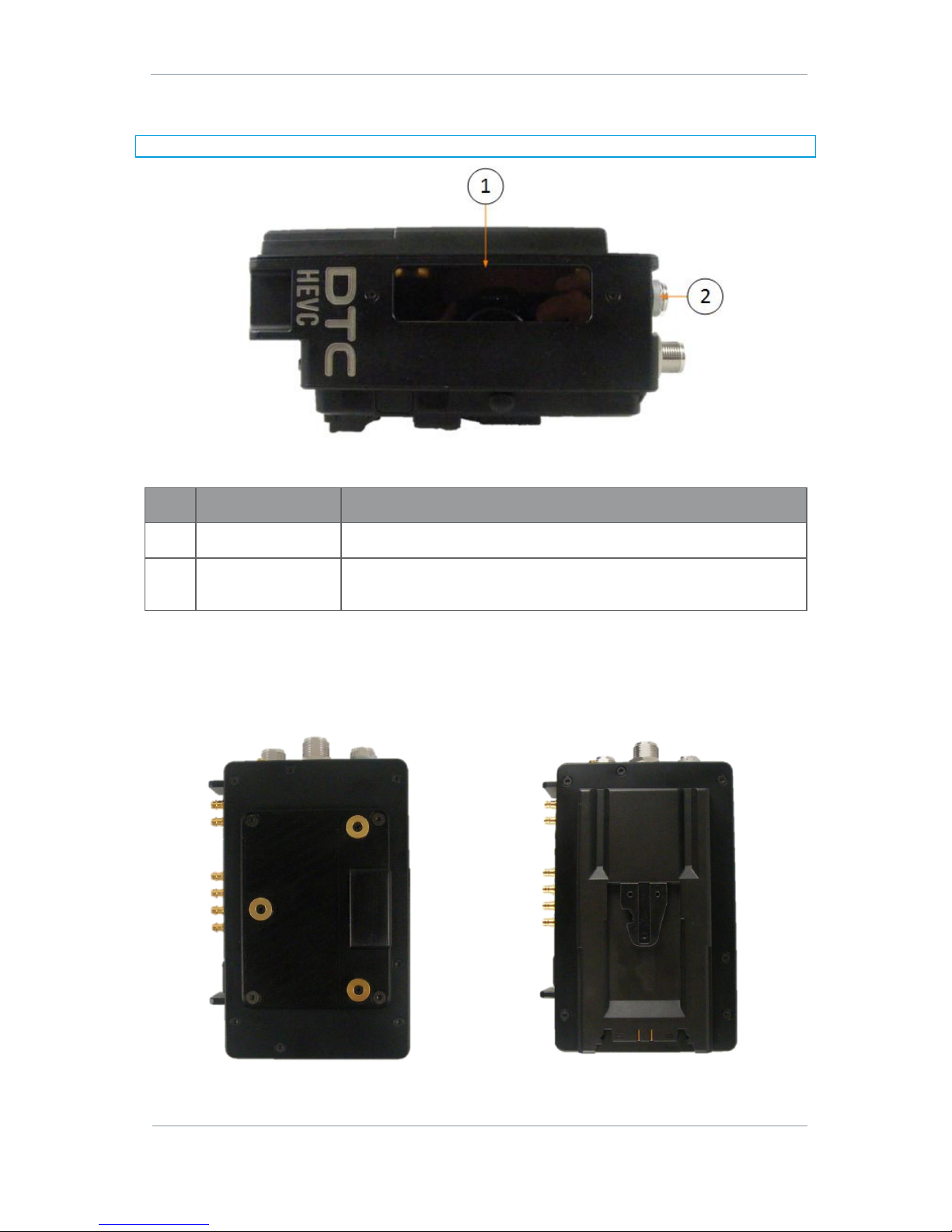
Left Panel (LCD)
Note: For full details of LCD display operation, refer to Section 8.
Figure 3-4 AEON-TX Left Panel
No
Item
Purpose
1
LCD display
A sunlight-readable LCD display covering all major functions.
2
LCD display control
button
Use this button to navigate the LCD display menu.
Table 3-4 AEON-TX Left Panel Key
Camera Mount Plate
The AEON-TX camera mount plate will assemble the AEON-TX to the camera. The AEON-TX will have either
an AB or V mount option.
Figure 3-5 AB Camera Mount (left) and V Camera Mount (right)
Page 21
AEON Family User Guide
Commercial in Confidence
Video, Broadcast
100249
Revision: 1.0
Commercial in Confidence
Page 3-14
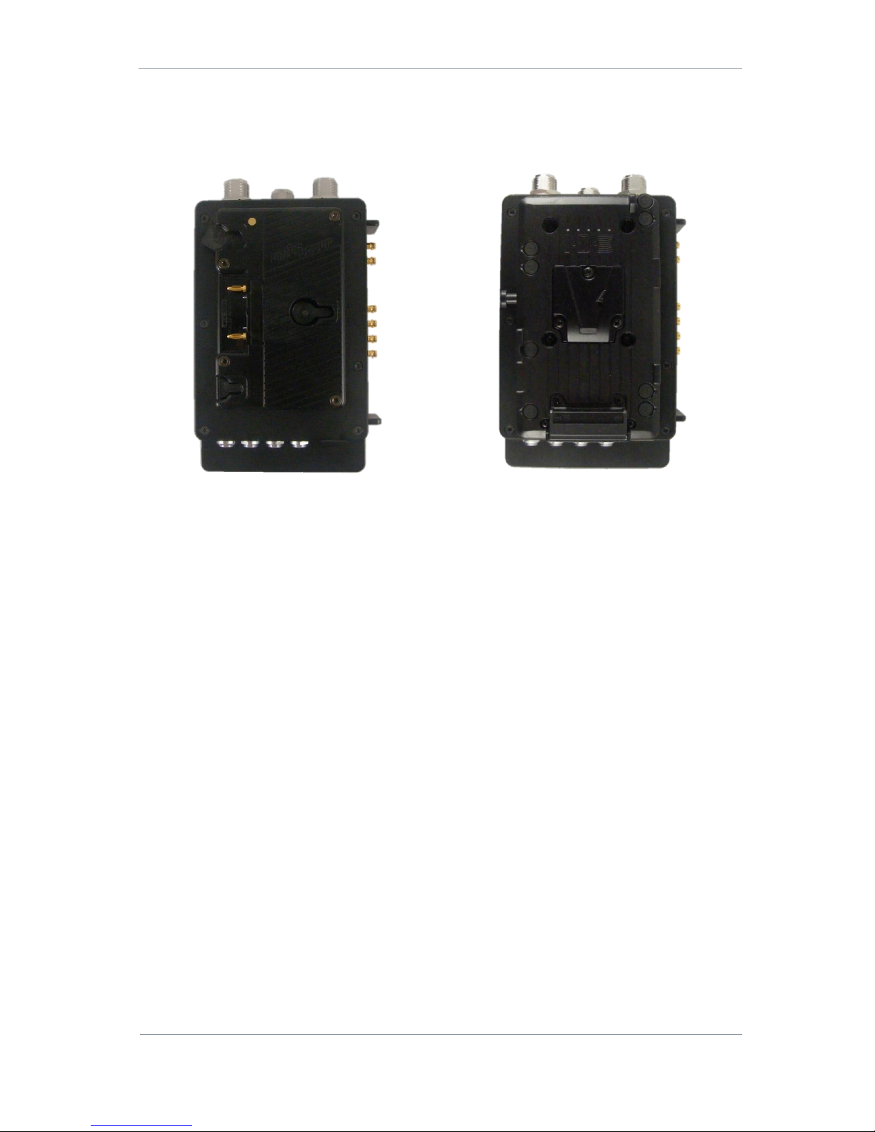
Battery Mount Plate
The AEON-TX battery mount plate will assemble the battery to the AEON-TX. The AEON-TX will have either AB
or V mount option.
Figure 3-6 AB Battery Mount (left) and V Battery Mount (right)
Page 22
AEON Family User Guide
Commercial in Confidence
Video, Broadcast
100249
Revision: 1.0
Commercial in Confidence
Page 3-15
3.3 AEON Rack Decoder/Encoder
Front Panel
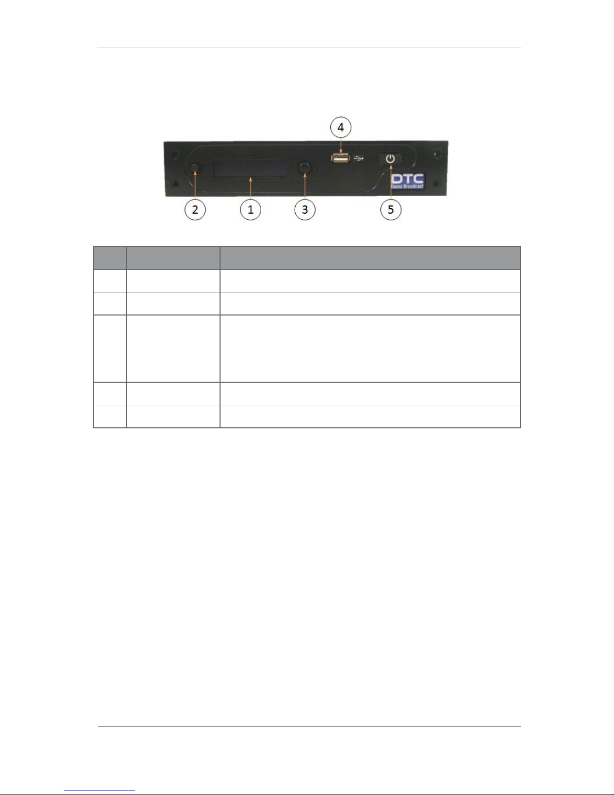
Figure 3-7 AEON Decoder/Encoder Front Panel
No
Item
Purpose
1
OLED display
A sunlight-readable OLED display covering all major functions.
2
Cancel button
Each time you push the button, the menu moves back a level.
3
Navigation button
Push the Navigation button to select menus or options.
Move the button up and down to move between menus or change options.
Move the button left and right to select numbers/letters when editing
values.
4
USB jack
USB host or peripheral device connection.
5
Power button
Push to toggle the power on or off.
Table 3-5 AEON Decoder/Encoder Front Panel Key
Page 23
AEON Family User Guide
Commercial in Confidence
Video, Broadcast
100249
Revision: 1.0
Commercial in Confidence
Page 3-16
Rear Panel
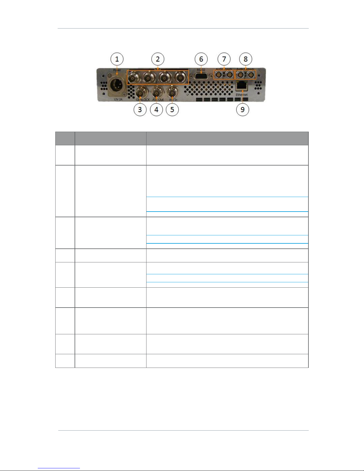
Figure 3-8 AEON Decoder/Encoder Rear Panel
No
Item
Purpose
1
XLR 4-way jack (pins)
Use the supplied CA0649 PSU to supply 12V DC input (9V – 18V)
to the unit.
2
BNC jack (socket) x 4
3G-SDI video output/inputs.
Outputs for the Decoder.
Inputs for the Encoder.
Note: The Decoder outputs currently only support 3G-SDI Level A
signals.
3
BNC jack (socket)
Genlock input to keep the receiver synchronised with all the other
equipment in your facility.
Note: Future development on the Encoder.
4
BNC jack (socket)
ASI video output.
5
BNC jack (socket)
ASI video input.
Note: Future development on the Encoder.
6
9-way D-type connector
(sockets)
RS-232 data communications; Input – Encoder; Output – Decoder.
See Section 11.3 for pinout.
7
5-way Lemo jack (sockets)
x 2
Encoder only – channel 1 and 2 balanced left and right audio
input with switchable phantom power, use supplied CA0579
cable. See Section 11.3 for pinout.
8
5-way Lemo jack (sockets)
x 2
Decoder only – channel 1 and 2 balanced left and right audio
output, use supplied CA0512 cable. See Section 11.3 for pinout.
9
RJ45 jack
Ethernet connection for IP control.
Table 3-6 AEON Decoder/Encoder Front Panel Key
Page 24

AEON Family User Guide
Commercial in Confidence
Video, Broadcast
100249
Revision: 1.0
Commercial in Confidence
Page 4-17
4. Getting Started
These instructions give the information required to power up and control an AEON device.
4.1 Power
AEON Transmitter
There is no power switch, the AEON Transmitter will start the moment the power supply is connected.
Power can be supplied to the AEON Transmitter in two ways:
Via a battery – AB or V mount depending on the device battery mounting plate
Via 9.2–17.8VDC input to the power connector on the bottom panel
AEON Decoder/Encoder
Power to the AEON Encoder or Decoder is supplied via the 12–17V DC input on the rear panel via the
supplied CA0649 12V PSU. Power on/off is controlled by the front panel switch.
Push and release to switch on, the switch will latch. Push and release to switch off, the switch will unlatch.
4.2 Access the USB Stick
The USB support stick includes this user guide plus Node Finder, an application which you will need to
establish the AEON Transmitter IP address.
1. Plug the USB stick into the USB port of your PC.
2. The USB stick device drivers will load the first time you plug it in to your PC. Wait for the drivers to load
successfully, you should see the progress in the bottom right of your PC screen.
3. Once they have loaded, a USB drive will have been created. Open Windows Explorer and you will be able
to view the USB stick contents.
Page 25
AEON Family User Guide
Commercial in Confidence
Video, Broadcast
100249
Revision: 1.0
Commercial in Confidence
Page 4-18
4.3 Using Node Finder
Introduction
Our devices are shipped to you with the IP DHCP setting enabled. This means that if the AEON Transmitter
is connected to a network which is administered by a DHCP server, the IP address will be automatically
allocated to it.
Node Finder can be used to identify a device IP address, or disable DHCP if you are not connected through a
DHCP server or using a standalone PC or laptop.
If you are unsure about your server settings, check with your Network Administrator.
Note: If you are using a standalone PC or laptop, you will also need to set the IP address of the PC. Refer to
Section 11.1 to find out how to do this.
If the DTC device is connected to a network which does not have a DHCP server, contact your Network
Administrator for an IP address you can use.
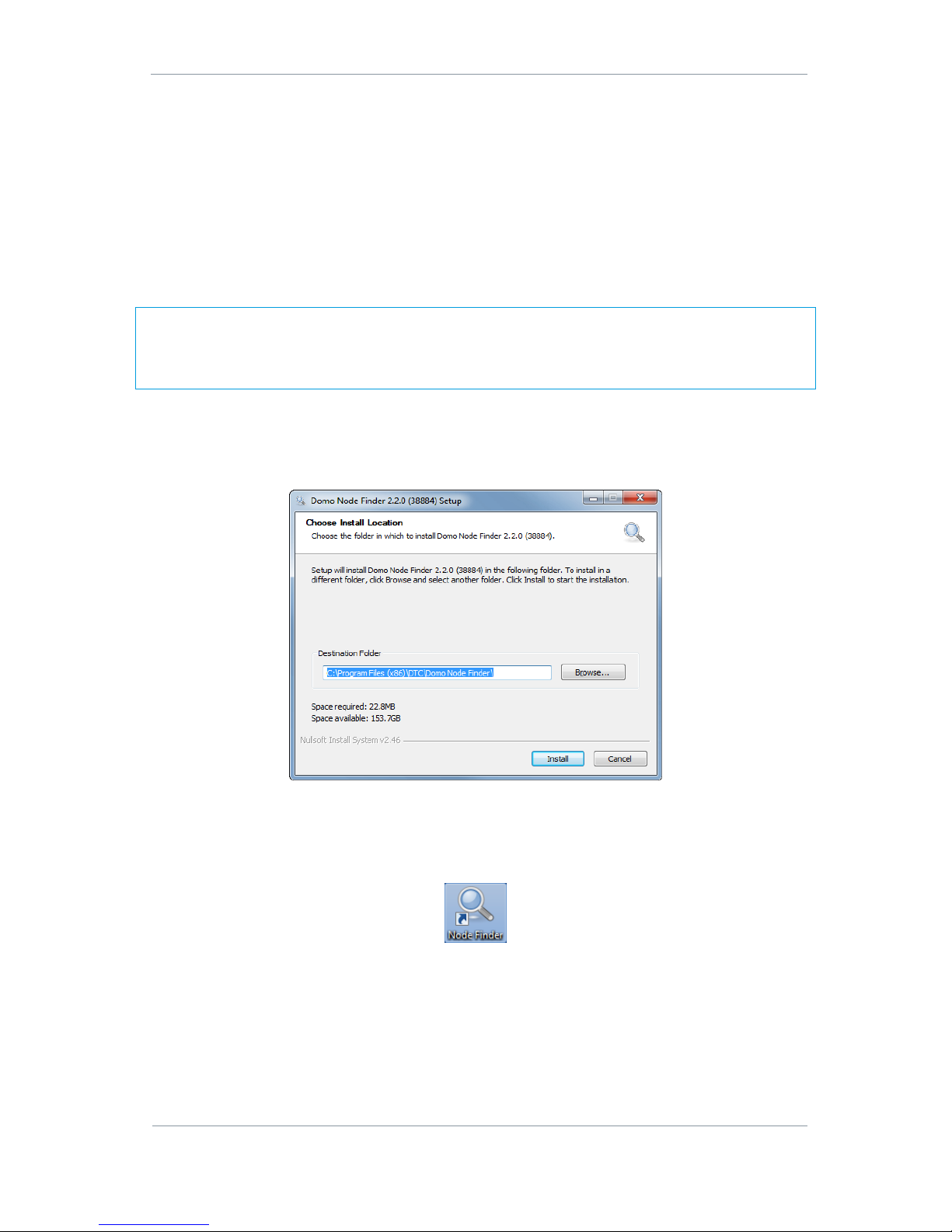
Install Node Finder on your PC
1. Double click the NodeFinder.exe file from the USB drive on your PC.
2. The Node Finder Setup window opens.
3. Browse to the location where you wish to install the software or leave the Destination Folder at default
(recommended).
4. Click the Install button.
5. On completion Close the installer. A Node Finder icon will appear on your desktop.
Page 26
AEON Family User Guide
Commercial in Confidence
Video, Broadcast
100249
Revision: 1.0
Commercial in Confidence
Page 4-19
Establish the AEON Transmitter’s IP Address using Node Finder
1. Power up the AEON Transmitter using one of the methods explained above.
2. Double click the newly installed Node Finder icon from your PC desktop.
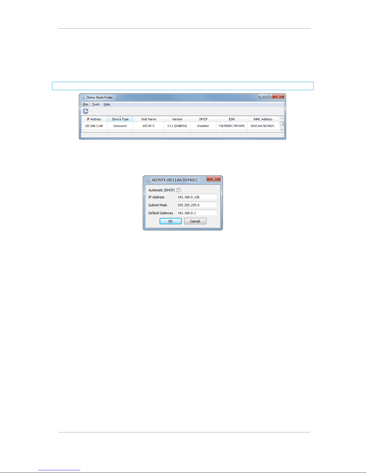
3. Find the AEON Transmitter IP address from the Node Finder list.
Note: If the device is not connected to a network with a DHCP server, the IP address may appear as 0.0.0.0.
Figure 4-1 Node Finder Showing an AEON Transmitter
4. Right click on the IP address and select Configure Network to disable DHCP and set a fixed IP address,
if required. The IP Address should be on the same address range as the network or standalone PC, the
Subnet Mask should be left at 255.255.255.0 and the Default Gateway can be 0.0.0.0.
Figure 4-2 Node Finder IP Address Configuration
Page 27
AEON Family User Guide
Commercial in Confidence
Video, Broadcast
100249
Revision: 1.0
Commercial in Confidence
Page 4-20
4.4 AEON Transmitter Web Browser Control
Now the IP address has been established, you can use a web browser to configure and monitor the AEON
Transmitter.
Note: Although all web browsers may work with AEON devices, some operations cannot be guaranteed. DTC
strongly recommend the use of Google Chrome.
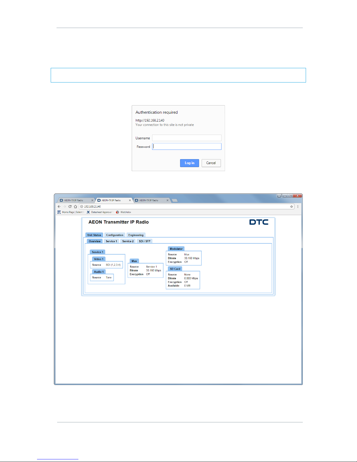
1. Open a web browser and enter the IP address of the AEON device in the address bar.
2. An authentication required dialogue box will open.
3. The Password is aeonweb which is case sensitive. The Username should be left blank
4. Click Log in, the web browser control application opens.
Figure 4-3 Web Browser Communications with an AEON Transmitter
Page 28

AEON Family User Guide
Commercial in Confidence
Video, Broadcast
100249
Revision: 1.0
Commercial in Confidence
Page 4-21
4.5 Web Browser Options
The web browser display options will change depending on the modes that are set. The guides that follow
will explain the differences where applicable:
AEON Transmitter Web Browser Operation
AEON Transmitter – SDR Dual Encoder
AEON-MESH Web Browser Operation
4.6 LCD/OLED Display Control
The AEON Transmitter, Encoder and Decoder can be operated from an integral LCD/OLED display via control
buttons.
For details on LCD display control for the Transmitter, refer to Section 8 and for Decoder/Encoder OLED
display, refer to Section 9.
Page 29
AEON Family User Guide
Commercial in Confidence
Video, Broadcast
100249
Revision: 1.0
Commercial in Confidence
Page 5-22
5. AEON Transmitter Web Browser Operation
5.1 Introduction
AEON Transmitters can be controlled from a web browser application via an Ethernet to setup predeployment configurations.
Note: Although all web browsers may work with AEON Transmitter, some operations cannot be guaranteed.
DTC strongly recommend the use of Google Chrome.
This section explains the web browser operation, explaining each parameter. It will help you understand how
to operate the AEON Transmitter to optimise performance.
Note: There are some configurations that will change the selections sufficiently to warrant separate
explanation. Please see Section 6 when in Dual SDR mode and refer to Section 7 when you configure the
AEON Transmitter to MESH application.
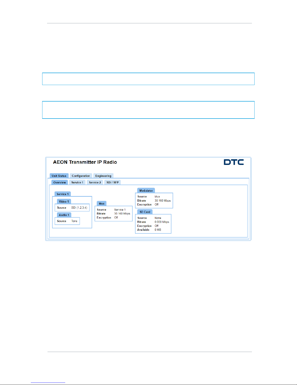
5.2 Unit Status>Overview Tab
The Overview tab shows status information. The displayed information may depend on what functions have
been enabled.
Page 30
AEON Family User Guide
Commercial in Confidence
Video, Broadcast
100249
Revision: 1.0
Commercial in Confidence
Page 5-23
5.3 Unit Status>Service>Status
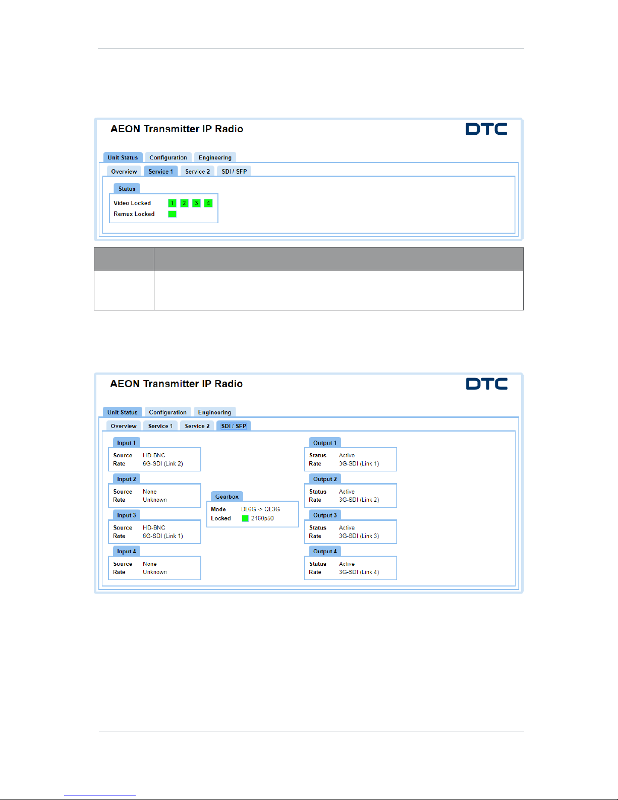
The Service tab shows video status information. The Service 1 and Service 2 tabs display the status of the
respective services.
Property
Description
Status
Colour coded video and audio status.
White – not configured; Red – not locked to source; Green – locked to source
5.4 Unit Status>SDI/SFP Tab
The SDI/SPF tab gives an overview of the ‘gearing’ of the video inputs to outputs.
Page 31
AEON Family User Guide
Commercial in Confidence
Video, Broadcast
100249
Revision: 1.0
Commercial in Confidence
Page 5-24
5.5 The Apply, Save and Refresh Buttons
The Global and Configuration tabs have the Apply, Save and Refresh buttons. It is useful to know the
differences and important to remember to click Apply or Save when any changes are made.
Apply Button
Click Apply in the bottom left of the screen to save the changes you have made. This will also make the
preset active.
Save Button
Changes can be made to non-active presets by clicking Save. The green highlighted box will show which
preset configuration is active.
Refresh Button
If you make changes to parameters but do not click Apply or Save, you can click the Refresh button to
return the screen to the current settings.
5.6 Configuration>Global Tab
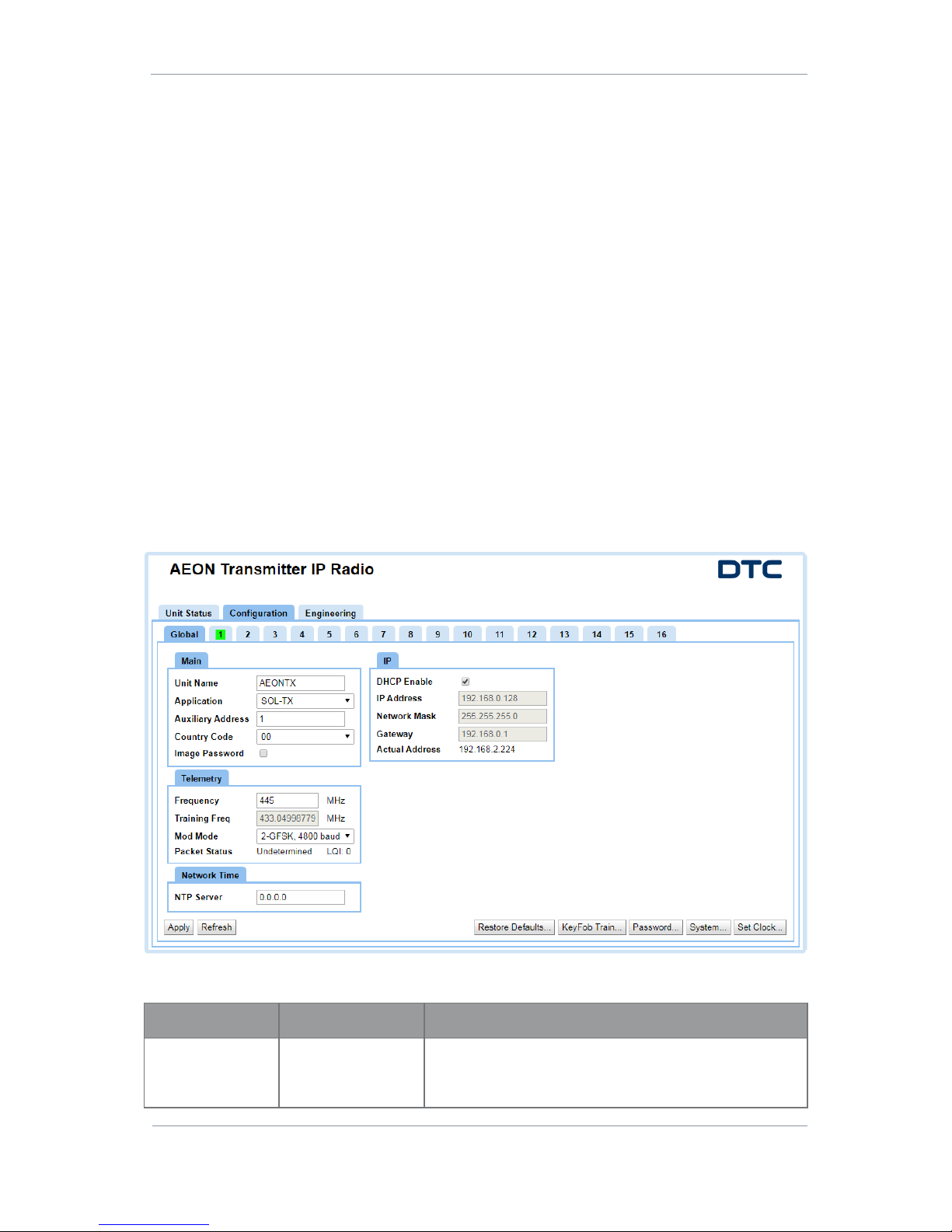
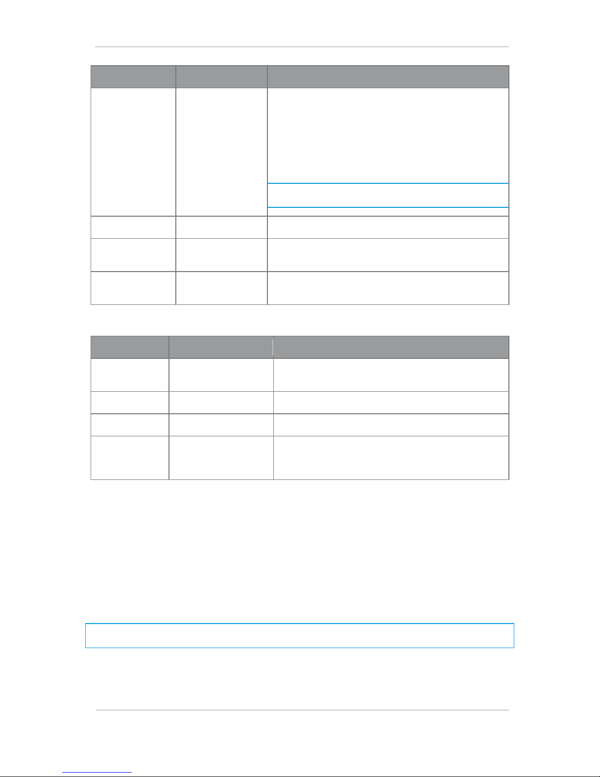
The Global allows you to change parameters which do not affect the preset settings.
If a 4G dongle is inserted into the USB port, Eth1 (modem) parameters will appear in the tab.
Main Parameters
Property
Value
Description
Unit Name
Up to 40
alphanumeric
characters
The unit name can be a friendly name to identify your AEON
Transmitter.
Page 32
AEON Family User Guide
Commercial in Confidence
Video, Broadcast
100249
Revision: 1.0
Commercial in Confidence
Page 5-25
Property
Value
Description
Application
MESH
SOL-TX
You can use this field to change the application of the
AEON Transmitter if it has both license applications
applied.
When in SOL-TX mode, the unit RF ports are all TX only.
When in MESH mode, the unit RF ports A and B become
transceivers. The device can be combined in a fluid selfhealing Mesh network containing up to 16 nodes.
Note: For detailed MESH user instructions you will have to
refer to NETNode Phase 5 Software User Guide.
Auxiliary Address
Default 1
It is recommended that this is left at the default value.
Country Code
ISO 3166-1 Alpha-2
code
If you are using a Wi-Fi dongle, you will need to select the
country code to assist with channel selection.
Image Password
Set or clear
If this is checked, it will ask for the AEON Transmitter
password if an image is copied.
Telemetry Parameters
Property
Value
Description
Frequency
A frequency in the range
of the telemetry receiver
The frequency range for the telemetry receiver is defined
by the part number of the unit.
Training Freq
Auto set
The frequency for the key fob transmitter.
Mod Mode
2-GFSK, 4800 baud
Only one Mod Mode is currently available.
Packet Status
Information only
Displays the current Received Signal Strength Indication
(RSSI) and Link Quality Indicator (LQI) of the telemetry
signal.
Network Time
Enter a Network Time Protocol (NTP) server IP address for clock synchronization to UTC time.
The default address is 0.0.0.0, in this condition there is no clock synchronisation.
IP Parameters
Our devices are shipped to you with the DHCP setting enabled. This means that if the AEON Transmitter is
connected to a network which is administered by a DHCP server, an IP address will be automatically
allocated to it.
If you are unsure about your server settings, check with your Network Administrator.
Note: If you are using a standalone PC or laptop, you will need to disable DHCP and set the IP address of
the PC. Refer to Appendix A – Reference Material to find out how to do this.
The following table details the IP parameters of the Global tab.
Page 33
AEON Family User Guide
Commercial in Confidence
Video, Broadcast
100249
Revision: 1.0
Commercial in Confidence
Page 5-26
Parameter
Value
Description
DHCP Enable
Set or clear
If selected, a DHCP server on the network will allocate an IP
address.
If clear, the IP Address, Network Mask and Gateway parameters
will need to be set manually.
IP Address
Example:
192.168.2.120
Type an IP address in the text box.
Network Mask
Example:
255.255.255.0
Type a Network Mask in the text box.
The Network Mask lets a network administrator divide a network
into smaller more efficient subnets to stop large numbers of IP
packets being routed through the network.
Gateway
Example:
192.168.2.254
Type a Gateway address in the text box.
A gateway is used by a host when an IP packet's destination
address belongs outside the local subnet. The default gateway
address is usually an interface belonging to the LAN’s router.
Actual Address
Indication only
This is the actual IP address that is allocated to the AEON
Transmitter by the DHCP server or if set manually.
4G LTE USB Dongle
When a 4G LTE USB Dongle is inserted in the USB port, an Eth1 (modem) tab will appear.
Parameter
Value
Description
Enable
Set or clear
When this is set, this will allow you to edit the IP settings.
Stream on Eth1
Set or clear
When this is set, this will allow you to stream over a 4G LTE
network.
Local IP
Address
192.168.8.2
This is the IP address of the 4G LTE dongle.
Local Network
Mask
255.255.255.0
This is the network mask of the 4G LTE dongle.
Gateway
192.168.8.1
This is the gateway address for the 4G LTE dongle.
Note: When you stream using the 4G dongle you will need to configure the Streamer settings accordingly.
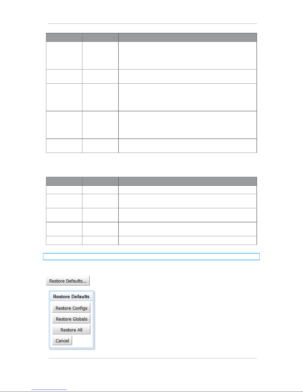
Restore Defaults Button
If you click on the Restore Defaults button a dialog box opens:
Restore Configs – restores the sixteen configurations to factory default
conditions
Restore Globals – restores the Global settings to factory default
conditions
Restore All – restores Global settings and all configurations to factory
default conditions
Page 34
AEON Family User Guide
Commercial in Confidence
Video, Broadcast
100249
Revision: 1.0
Commercial in Confidence
Page 5-27
KeyFob Train Button
Key Fob Training lets you link a key fob to your transmitter so that they can operate together. Click this
button to transfer the settings from the Key Fob Pane to the key fob.
1. Push button 2 and button 3 at the same time.
2. The key fob gives three buzzes.
3. Some seconds pass and the key fob gives two buzzes to indicate pairing is successful.
Password Button
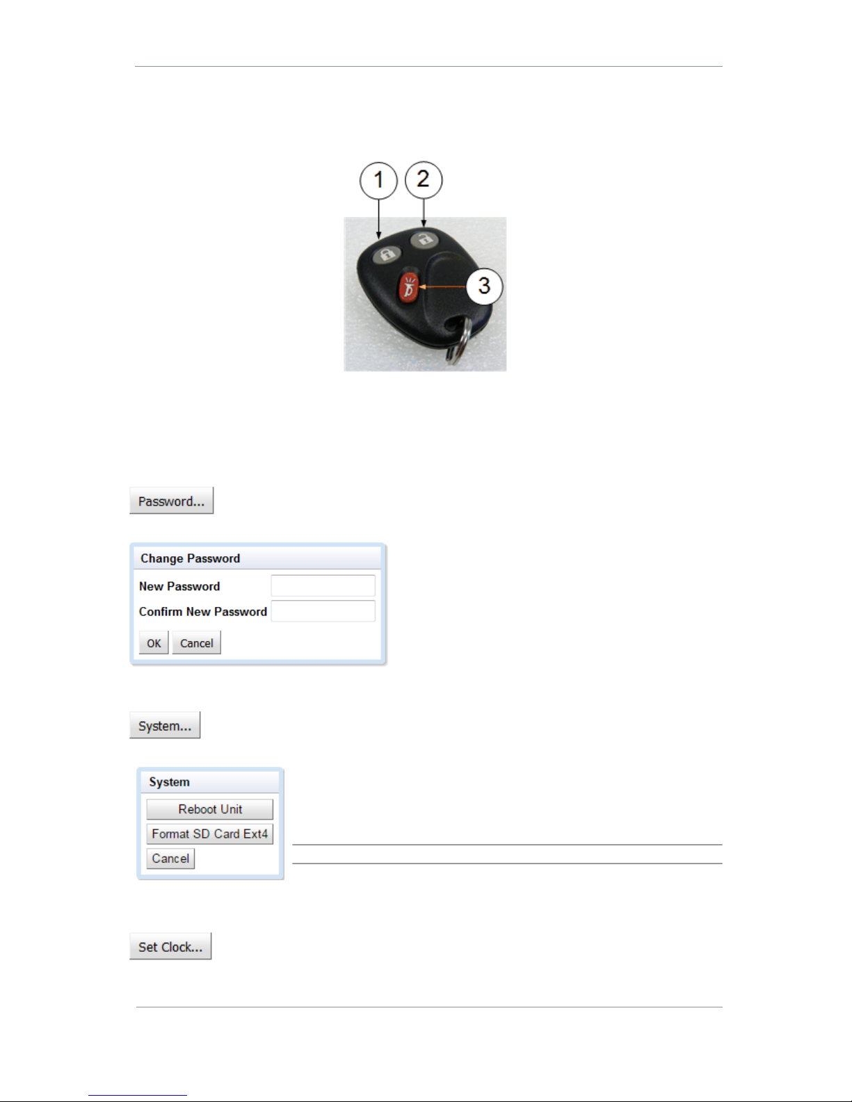
The Password button allows you to change the password for the AEON Transmitter. If you
click on it, the Change Password dialogue box opens:
System Button
The AEON Transmitter has an SD card which allows the user to store recordings. If you click on
the System button, a dialogue box opens:
Reboot Unit – will force a reboot of the AEON Transmitter
Format SD Card Ext4 – will format your SD card in the file system used
by Linux.
CAUTION: When you format an SD card it will delete all contents.
Set Clock Button
Click on the Set Clock button to set the date and time to UTC time.
Page 35
AEON Family User Guide
Commercial in Confidence
Video, Broadcast
100249
Revision: 1.0
Commercial in Confidence
Page 5-28
5.7 Configuration>Preset>Unit
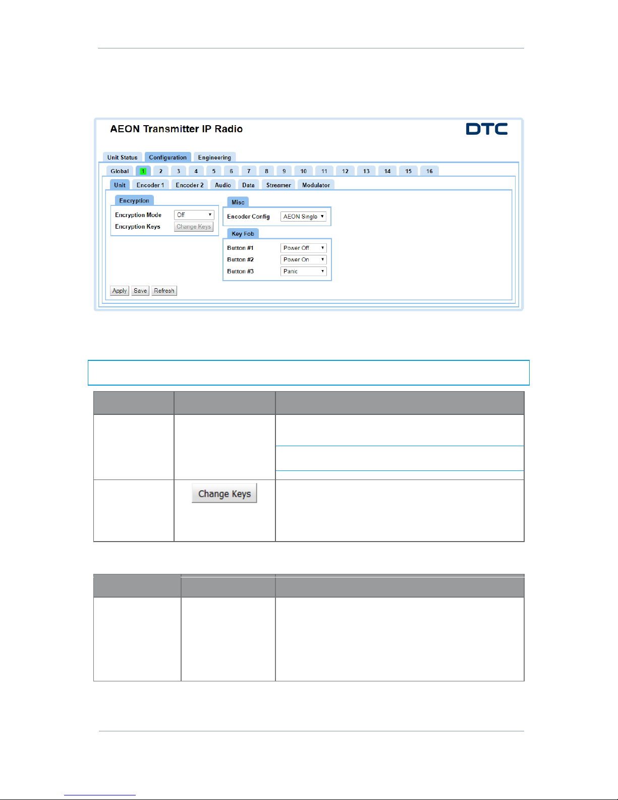
There are up to sixteen different preset Configurations that can be setup. In this example we are viewing
preset 1 which is highlighted with a green background to denote that it is active.
Encryption Pane
It may be very important to scramble video and audio before they are passed across networks.
Note: Encryption modes except ABS are licensed. If there is an encryption mode you want but does not
appear in the list, contact your DTC representative.
Property
Value
Description
Encryption Mode
Off, ABS
AES128, AES256
CCrypt, CCrypt256
Click on the box and select your encryption mode from the
dropdown list. The options will be license dependent.
Note: CCrypt encryption are included with the AES
encryption license.
Encryption Keys
If you click on this button the Scrambling Key dialogue box
will open. Enter the encryption key for your system.
When you click OK remember you will still need to click
Apply to activate the encryption.
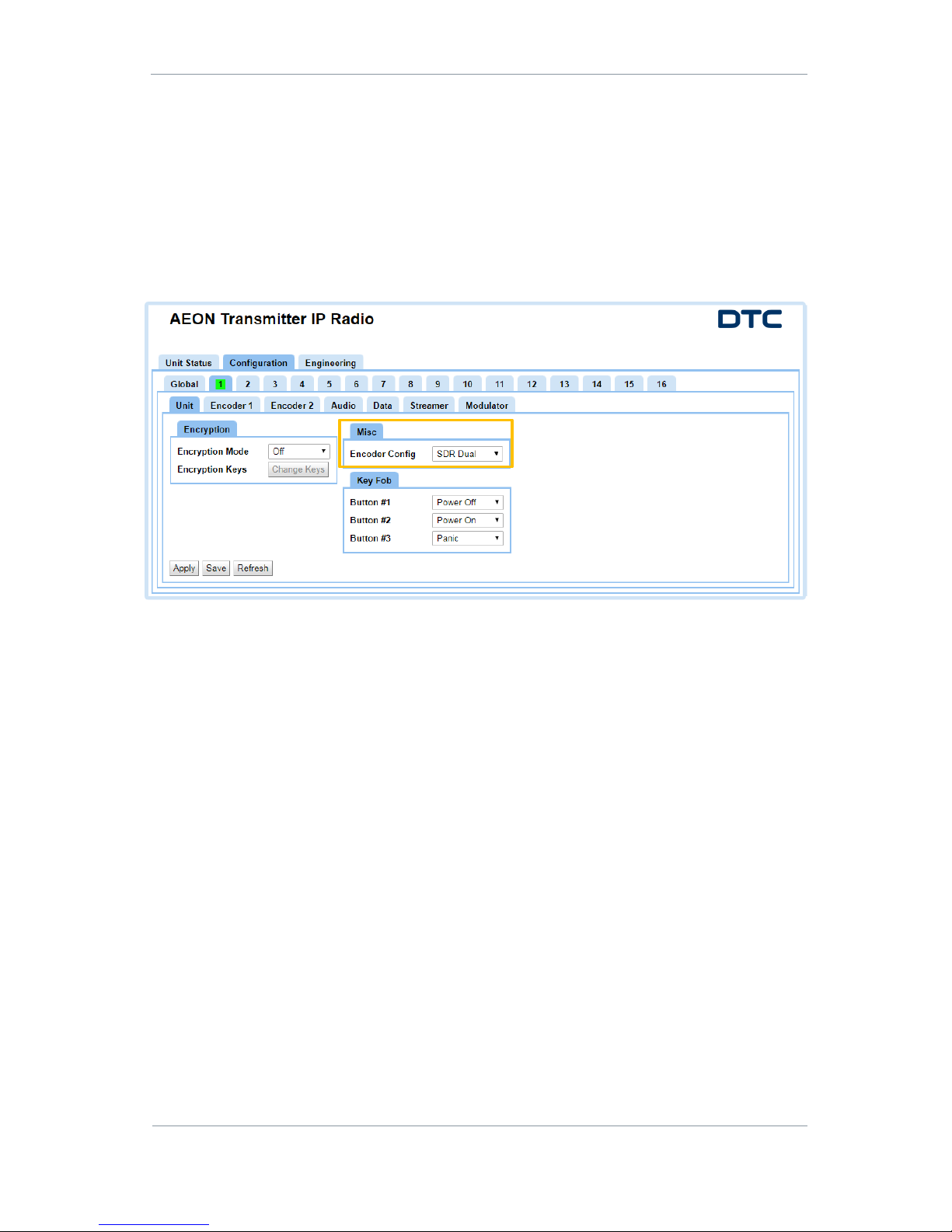
Misc Pane
Property
Value
Description
Encoder Config
SDR Dual
AEON Single
AEON Quad
When configured in AEON mode, the transmitter is capable
of encoding HEVC (H.265) video.
When configured as SDR Dual, the transmitter is switched
to a dual H.264 encoder with compatible operation to a DTC
SOL8SDR device. The web browser selections will change
significantly, see Section 6 for alternate configurations.
Page 36
AEON Family User Guide
Commercial in Confidence
Video, Broadcast
100249
Revision: 1.0
Commercial in Confidence
Page 5-29
Key Fob Pane
Property
Value
Description
Button #1
Button #2
Button #3
No Operation
Power Off
Power On
Mod Off
Mod On
Panic
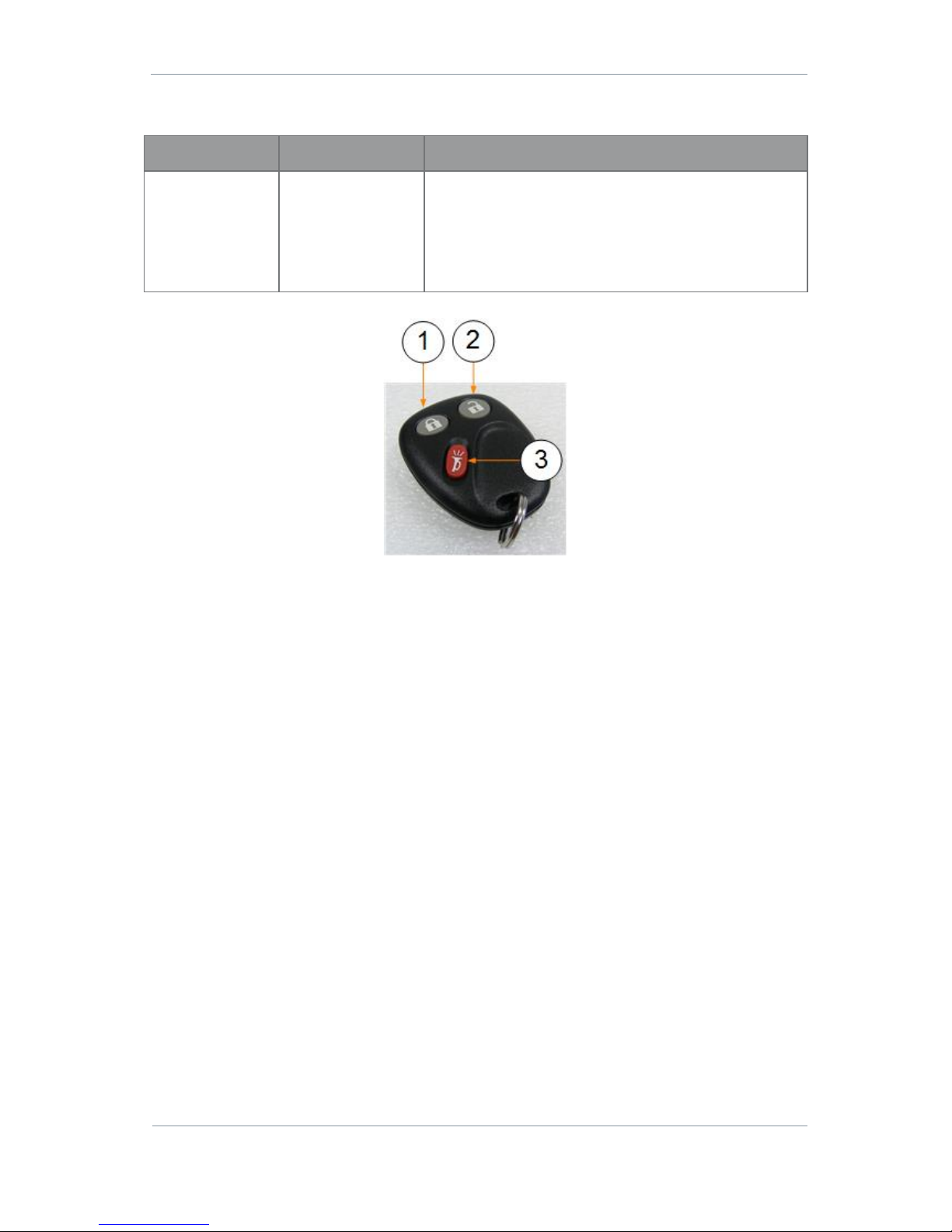
The AEON Transmitter can be remotely controlled with a key
fob. Each button can be configured for a different function,
see Figure 5-1.
The Key Fob settings can be transferred to the key fob by
clicking the KeyFob Train Button.
Figure 5-1 Key Fob Buttons
Page 37
AEON Family User Guide
Commercial in Confidence
Video, Broadcast
100249
Revision: 1.0
Commercial in Confidence
Page 5-30
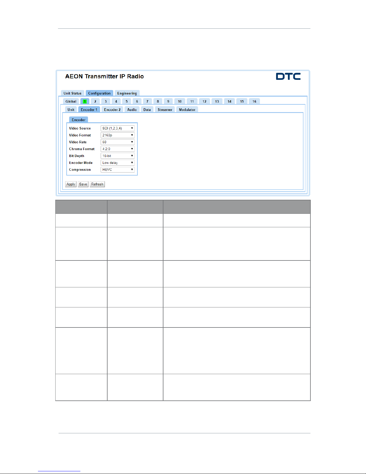
5.8 Configuration>Preset>Encoder Tab
There are up to sixteen different preset Configurations that can be setup. In this example we are viewing
preset 1 which is highlighted with a green background to denote that it is active.
Property
Value
Description
Video Source
SDI (1,2,3,4)
Select the video input source
Video Format
480i, 576i,
480p, 576p, 720p,
1080i, 1080p,
1080psf, 2160p
Select the video format.
Video Rate
23.976, 24, 25,
29.97, 30, 50,
59.94, 60
Select the video frame rate.
Chroma Format
4:2:0
4:2:2
Select the level of chroma sampling required.
Bit Depth
8-bit
10-bit
Select the number of bits per pixel.
Encoder Mode
Standard delay
Low delay
Select the level of delay.
Standard delay provides higher picture quality at the
expense of delay.
Low Delay provides very low delay at the expense of picture
quality.
Compression
HEVC
AVC
MPEG2
When the AEON Transmitter encoder config is set to AEON
Single, the encoding mode will always be HEVC.
Page 38
AEON Family User Guide
Commercial in Confidence
Video, Broadcast
100249
Revision: 1.0
Commercial in Confidence
Page 5-31
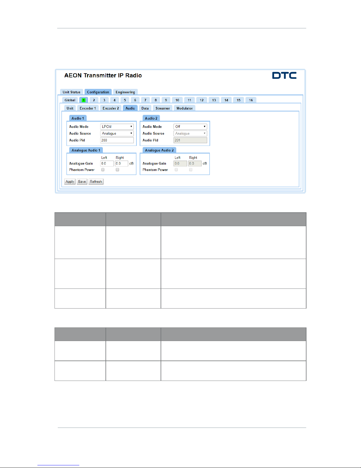
5.9 Configuration>Preset>Audio Tab
There are up to sixteen different preset Configurations that can be setup. In this example we are viewing
preset 1 which is highlighted with a green background to denote that it is active.
Audio
Property
Value
Description
Audio Mode
Off
LPCM
AAC
MP2
Select the audio format.
Audio Source
Analogue
Embedded
Tone
Select the audio source.
A test tone can be selected which is generated internally by
the AEON Transmitter.
Audio Pid
Default 200
This sets the PID for the audio content in the Service. The
Audio PID is listed in the PMT (see Section 5.11).
Analogue Audio
Property
Value
Description
Analogue Gain
Up to 40dB
Gain can be applied at the left and right inputs if the
source is at low level.
Phantom Power
Set or clear
When set, this will apply 48V phantom power to the
microphone, if required.
5.10 Configuration>Preset>Data Tab
Not currently available when the encoder is configured in AEON Single mode.
Page 39
AEON Family User Guide
Commercial in Confidence
Video, Broadcast
100249
Revision: 1.0
Commercial in Confidence
Page 5-32
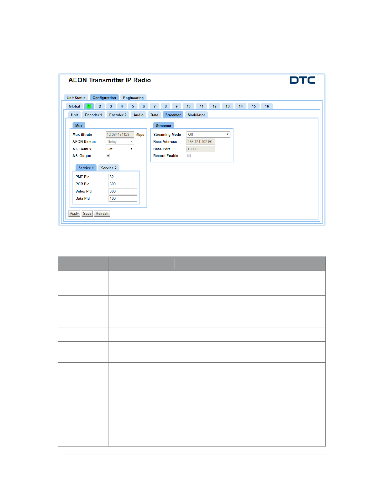
5.11 Configuration>Preset>Streamer
There are up to sixteen different preset Configurations that can be setup. In this example we are viewing
preset 1 which is highlighted with a green background to denote that it is active.
Mux Pane
The Mux Pane has settings relating to the Mux and Program properties.
Property
Value
Description
Mux Bitrate
Up to 50Mbits/s
The multiplexer bitrate for the service.
If the Modulation is set to Off, this can be set manually.
AEON Remux
Relay
Set by default to Relay mode.
This means that only services encoded by the AON
Transmitter can be streamed.
ASI Remux
Off
ASI Remux cannot be set.
ASI Output
Set or clear
When set, the ASI output will contain the same content
sent over the modulator.
PMT Pid
32 to 8190
This sets the packet id for the Program Map Table. For
each Program, there is one PMT.
These can be edited but should be left to default unless
an advanced user.
PCR Pid
32 to 8190
This sets the packet id for the Program Clock Reference
which is used to sync the audio and video. The PCR PID is
listed in the PMT.
These can be edited but should be left to default unless
an advanced user.
Page 40

AEON Family User Guide
Commercial in Confidence
Video, Broadcast
100249
Revision: 1.0
Commercial in Confidence
Page 5-33
Property
Value
Description
Video Pid
32 to 8190
This sets the packet id for the video content in the
Program. The Video PID is listed in the PMT.
These can be edited but should be left to default unless
an advanced user.
Data Pid
32 to 8190
This sets the packet id for the data content in the
Program. The Data PID is listed in the PMT.
These can be edited but should be left to default unless
an advanced user.
Note 1: The mux bitrate must be equal to or greater than the total bit rate of services and inputs. If the total
bit rate exceeds the mux bitrate the output stream won’t work.
Note 2: If you set ASI Remux to Relay it disables the video source for that channel. You must switch ASI
Remux Off when you want to reselect a video source.
Streamer Pane
Property
Value
Description
Streaming Mode
Off
UDP
RTSP Unicast
RTSP Multicast
RTP
RTP-Z
Select the streaming mode you wish to operate with.
Streams can be played back using VLC or Domo Video
Player (requires a license).
Note: RTP-Z is DTC’s compressed RTP. You will need
Domo Video Player to run streams using this protocol.
Base Address
For example:
237.103.227.228
This enables you to change the address used by the unit
for streaming. The default value is random to make sure
different transmitters have different multicast addresses.
Base Port
10000 or above
UDP uses port numbers in the header to direct traffic
around the network.
A good rule is to use numbers above 10000 to avoid
conflict with existing services.
When you set up a port number on several computers on a
network they will all listen for packets directed to that
port.
Record Enable
Set or clear
When you select this box, the video will be recorded to the
built in SD card.
Page 41
AEON Family User Guide
Commercial in Confidence
Video, Broadcast
100249
Revision: 1.0
Commercial in Confidence
Page 5-34
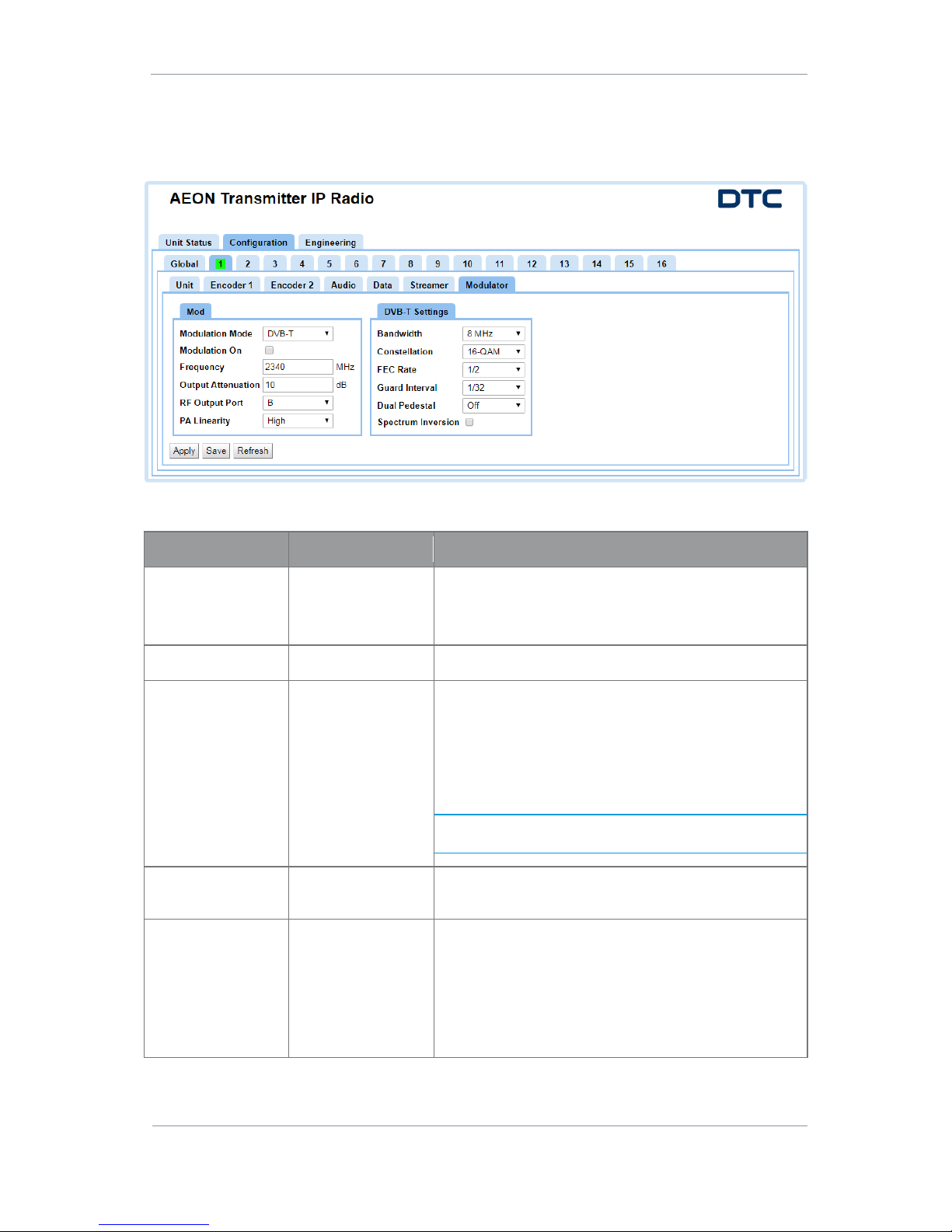
5.12 Configuration>Preset>Modulator Tab
There are up to sixteen different preset Configurations that can be setup. In this example we are viewing
preset 1 which is highlighted with a green background to denote that it is active.
Mod Pane
Property
Value
Description
Modulation Mode
None
DVB-T
NB/UMVL
Set the Modulation Mode for your system.
When you set this, the Settings pane will change
accordingly to DVB-T or NB/UMVL Settings.
Modulation On
Set or clear
Sets the RF output On or Off.
Frequency
Determined by unit
variant.
Type in the frequency you wish to use for the system. This
must be the same on the receiver.
When you use a frequency in the primary COFDM band, RF
ports A and B are active.
When you use a frequency in the secondary frequency
band, RF port C becomes active.
Note: The primary and secondary frequency bands are
defined by the transmitter variant. See Section 2.7.
Output Attenuation
0 to 32
Attenuation can be applied to the output of the
transmitter.
RF Output Port
A
B
A+B
C
The transmitter has three COFDM antennas, A, B and C.
When transmitting in the primary COFDM band, B is
selected as the output antenna by default but you can
select A or A+B if required.
When transmitting in the secondary COFDM band, C will
be selected automatically and greyed out.
Page 42

AEON Family User Guide
Commercial in Confidence
Video, Broadcast
100249
Revision: 1.0
Commercial in Confidence
Page 5-35
Property
Value
Description
PA Linearity
High
Low
High linearity, improves COFDM shoulder performance at
the expense of power consumption.
Usually used when working with power amplifiers which
must have excellent shoulder performance, or for
improved adjacent channel performance.
DVB-T or NB/UMVL Settings Pane
Note: The properties of this pane will change depending on the Modulation Mode selected. Some of the
options may not be available for the selected Mode.
Property
Value
Description
Bandwidth
625kHz
1.25MHz
2.5MHz
6MHz
7MHz
8MHz
DVB-T modes give excellent data throughput but shorter
range than Narrowband modes.
Narrowband modes give excellent range and best use of
available channel bandwidth.
Ultra Mobile Video Link modes give higher data
throughput than Narrowband by using the same
bandwidths as DVB-T. UMVL will give an advantage over
DVB-T at C/X-band in short range mobile environments.
Constellation
QPSK
16-QAM
64-QAM
BPSK
8-PSK
The COFDM constellation in use.
QPSK, BPSK and 8-PSK - less user data, more robust,
more range.
16QAM - more user data, less robust, less range (link
performance reduced by 5db).
64QAM - max user data, least robust, least range.
FEC Rate
1/2
1/3
2/3
3/4
5/6
7/8
The forward error correction (FEC) rate.
1/2 means 1 bit out of 2 bits is data and thus 1 bit is
used for error correction.
7/8 means 7 bits out of 8 bits are data and thus 1 bit is
used for error correction.
More user data means better picture quality, but less error
correction means less robust signal and thus less range.
Guard Interval
1/32
1/16
1/8
1/4
The guard interval is an extension of the RF symbol period
to give immunity to reflections.
1/32 deals with fast reflections, more data, less range.
1/4 deals with slower reflections, less data, more range.
Page 43
AEON Family User Guide
Commercial in Confidence
Video, Broadcast
100249
Revision: 1.0
Commercial in Confidence
Page 5-36
Property
Value
Description
Dual Pedestal
Off
Single Port
Dual Port
Only available in DVB-T. Dual Pedestal mode will double
the bitrate by using two adjacent COFDM channels with
1MHz separation. i.e. DVB-T 8MHz in dual pedestal mode
will give a total bandwidth of 17MHz.
Single Port (A or B OR A+B) – 100mW output for both
channels on a single port.
Dual Port (A+B) – 100mW output for each channel on
both ports (200mW total).
Note: Dual port (A+B) will give the best adjacent channel
performance at higher power but will produce more heat.
Ensure sufficient cooling is provided.
Spectrum Inversion
Set or clear
You would only set this if you needed to invert the COFDM
spectrum.
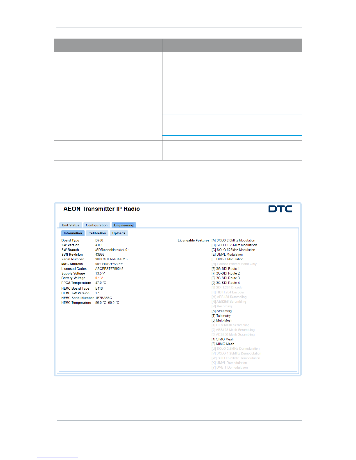
5.13 Engineering>Information Tab
The Information tab provides software and licensing information that may be useful during a service call. It
also gives voltage and temperature measurements of the internal PCBs for monitoring.
Page 44
AEON Family User Guide
Commercial in Confidence
Video, Broadcast
100249
Revision: 1.0
Commercial in Confidence
Page 5-37
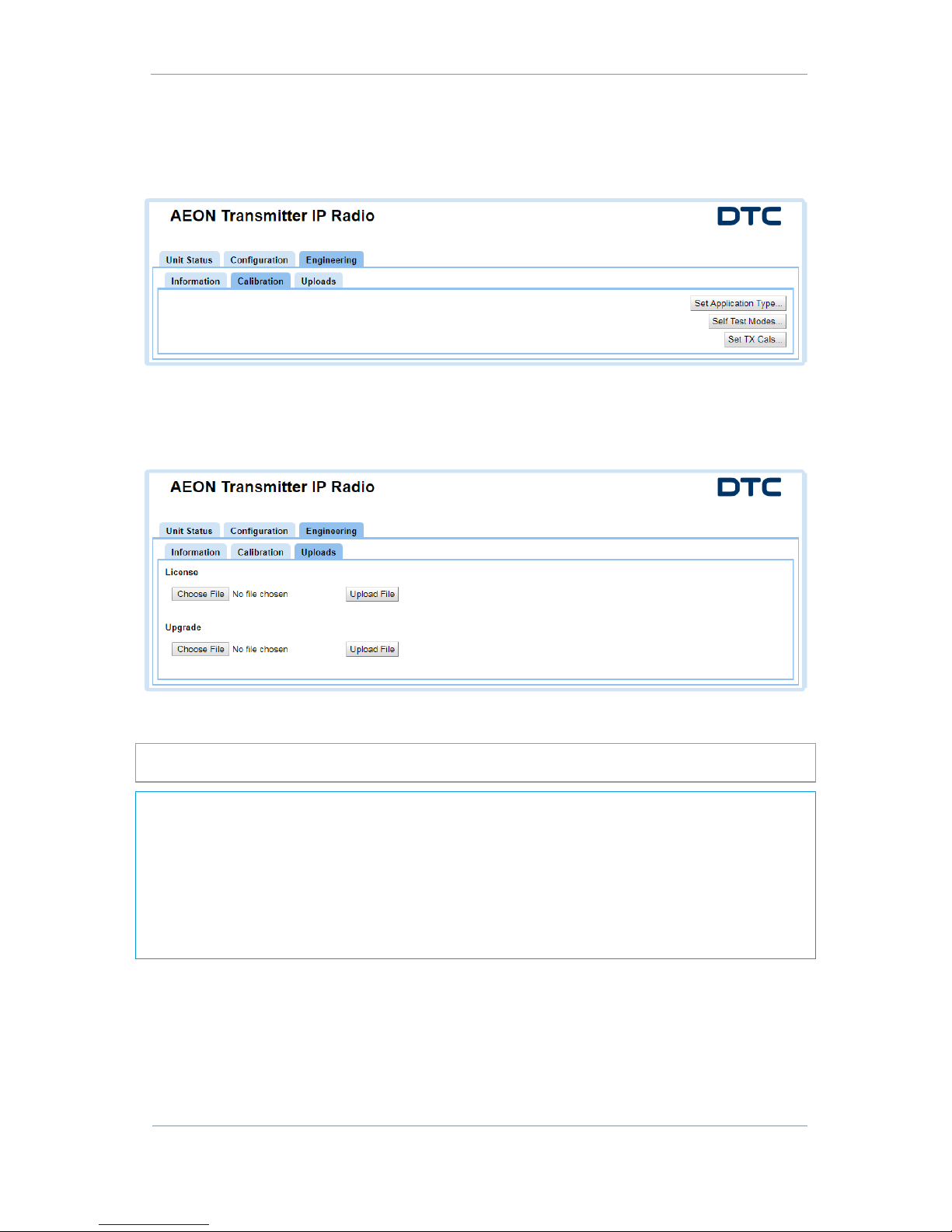
5.14 Engineering>Calibration Tab
These buttons can be used to set the calibration values of the AEON Transmitter. They are password
controlled and are used at DTC to configure the AEON Transmitter for optimum RF performance prior to
shipment.
5.15 Engineering>Uploads
The Uploads tab enables you to send software upgrade files or upload a license file to enable new features.
When upgrading software, a Please Wait - Unit Upgrading message will be displayed for a while before the
browser times out.
CAUTION: It is essential that the AEON Transmitter is not powered down at this stage, the upgrade will be
complete when the unit reboots.
Note: The upgrade involves uploading the code to the on-board SD card which then writes the code to the
flash. During the writing cycle, the unit will lose web browser control for several minutes depending on how
many parts of the code need to be upgraded.
A useful way to observe this cycle is to open a command prompt (enter cmd in the Windows Start Menu
search box) and enter a permanent ping command, the syntax for this is:
ping -t <AEON-TX_ip_address> e.g. ping -t 192.168.2.133
The pings will reply for a while then time out (the write cycle). When the pings reply again, the AEON
Transmitter will have rebooted and the upgrade is complete.
When the upgrade is complete, the web browser can be recovered. Refresh the web browser to view the new
software version in the Information tab.
Page 45
AEON Family User Guide
Commercial in Confidence
Video, Broadcast
100249
Revision: 1.0
Commercial in Confidence
Page 6-38
6. AEON Transmitter – SDR Dual Encoder
6.1 Introduction
SDR Dual is a configuration which will set the AEON Transmitter as a dual H.264 encoder compatible with
existing DTC H.264 receiver products.
When SDR Dual is selected as the Encoder Config in the Configuration>Preset>Unit tab, some of the views
and selections will change accordingly.
This section will show only the tabs which have changed as a result of this configuration.
Page 46
AEON Family User Guide
Commercial in Confidence
Video, Broadcast
100249
Revision: 1.0
Commercial in Confidence
Page 6-39
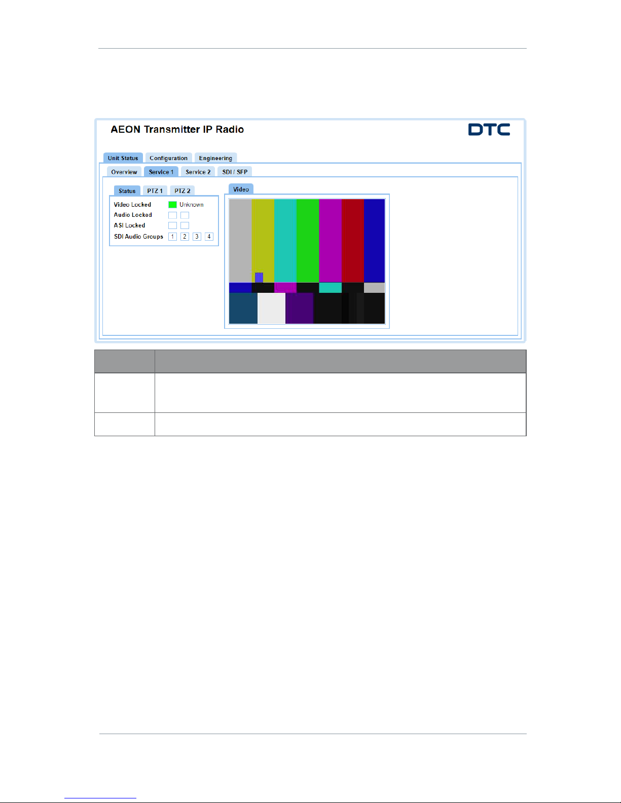
6.2 Unit Status>Service>Status Tab
The Status tab displays video and audio status information. The Service 1 and Service 2 tabs display the
status of the respective Services.
Property
Description
Status
Colour coded video and audio status.
White – not configured; Red – not locked to source; Green – locked to source
Video
This is an MJPEG display of the video for the Service.
Page 47
AEON Family User Guide
Commercial in Confidence
Video, Broadcast
100249
Revision: 1.0
Commercial in Confidence
Page 6-40
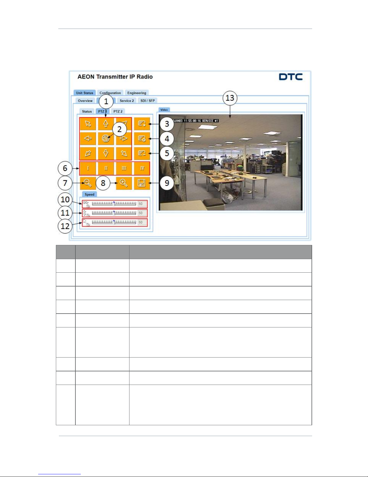
6.3 Unit Status>Service>PTZ Tab
The PTZ tab, allows you to control the pan-tilt-zoom and focus functions of an attached camera. Settings
can be saved to presets.
No
Property
Description
1
Pan/Tilt
Click to move the PTZ camera in the direction of the arrow.
2
Force Stop
Click to stop the PTZ movement immediately.
3
Focus Far
Click to move focus to objects far away.
4
Focus Stop
Click to stop focus movement.
5
Focus Near
Click to move focus to objects nearby.
6
Presets
Up to four PTZ configurations can be saved as presets in conjunction with
the Save button.
Click Save icon first, then select the Preset.
7
Zoom Out
Click to zoom out.
8
Zoom In
Click to zoom in.
9
Save
To be used in conjunction with the Preset button.
Click the Save button, it will turn from orange to green, this indicates that
the PTZ configurations can now be saved to a preset.
When you select the Preset, the Save icon will return to orange.
Page 48
AEON Family User Guide
Commercial in Confidence
Video, Broadcast
100249
Revision: 1.0
Commercial in Confidence
Page 6-41
No
Property
Description
10
Pan Speed
Drag and drop the slider or click on the scale to set the rate of left/right
movement.
11
Tilt Speed
Drag and drop the slider or click on the scale to set the rate of up/down
movement.
12
Zoom Speed
Drag and drop the slider or click on the scale to set the rate of zoom in/out
movement.
13
Video
An MJPEG video display for camera PTZ feedback.
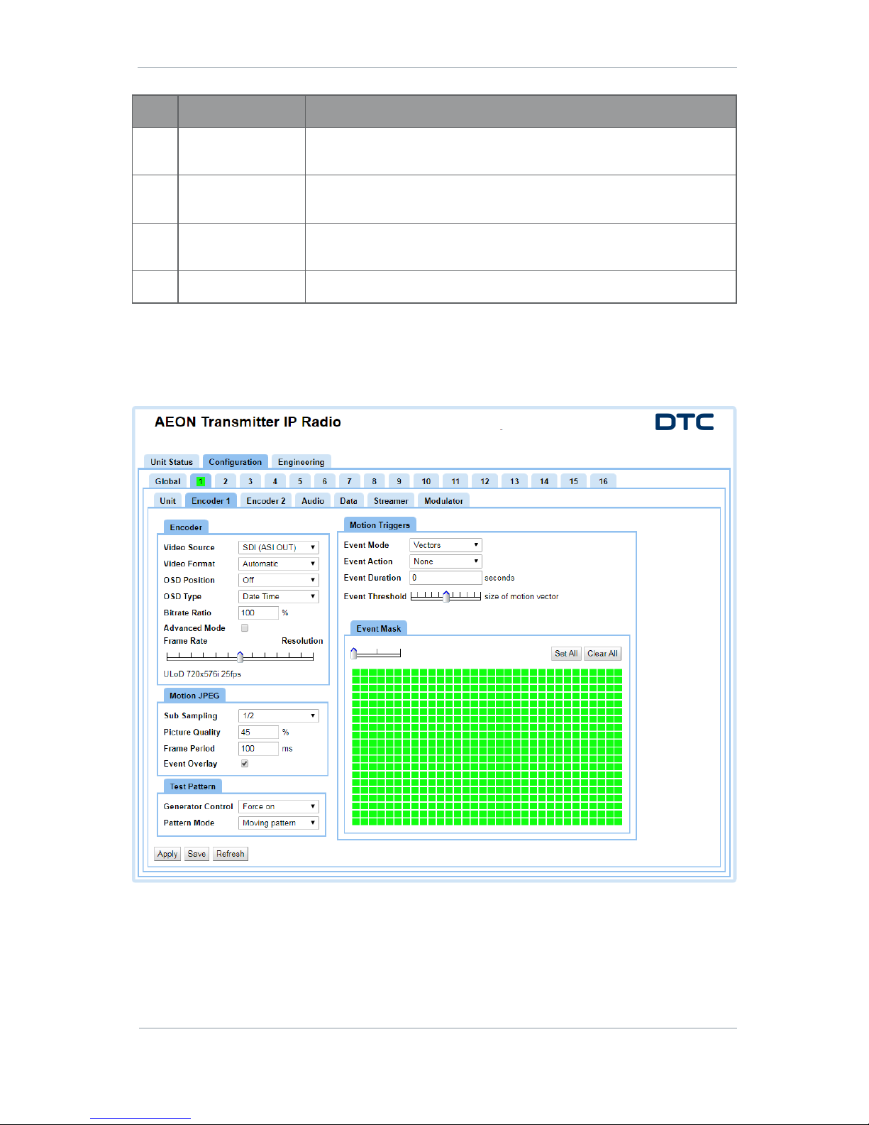
6.4 Configuration>Preset>Encoder Tab
There are up to sixteen different preset configurations that can be setup. In this example we are viewing
preset 1 which is highlighted with a green background to denote that it is active.
Page 49

AEON Family User Guide
Commercial in Confidence
Video, Broadcast
100249
Revision: 1.0
Commercial in Confidence
Page 6-42
Encoder Pane
Property
Value
Description
Video Source
Off
SDI (ASI IN)
MJPEG 1 (USB)
Select the video input source.
The physical port on the AEON Transmitter is indicated in
brackets.
Note: SDI input will only work when ASI IN is not being used
for Remux. See Section 0.
Video Format
Automatic
576i50 (PAL),
480i59 (NTSC)
720p50, 720p59,
720p60
1080i50, 1080i59,
1080i60
1080p23, 1080p24,
1080p25, 1080p29,
1080p30
1080psf23,
1080psf24,
1080psf25,
1080psf29,
1080psf30
Select the Video Format that aligns with the camera you
are operating.
The Automatic setting lets the AEON Transmitter establish
the signal automatically.
Power-up standard in Automatic mode defaults to PAL. This
can be changed by setting the input to NTSC for example
and then back to Automatic.
If video lock is lost for any reason, Automatic will need to
be re-applied.
OSD Position
Off
Top Left
Top Centre
Top Right
Centred
Bottom Left
Bottom Centre
Bottom Right
Sets the position of the On Screen Display (OSD) which will
appear on your screen when you play video.
OSD Type
Date Time
Service Name
Date Time Name
Will let you select what details appear on the OSD.
Bitrate Ratio
0 to 100%
Allocates more bitrate to one channel than the other.
For example you can have a high resolution image on the
high bit rate channel and a low resolution wide shot on the
low bit rate channel.
Advanced Mode
Set or clear
When this is clear, use the slider to auto set video encoder
settings.
When this is ticked, see below for Advanced settings.
Frame
Rate/Resolution
Slider
Auto set
The video settings will be automatically selected for
optimum performance by using this slider.
Page 50
AEON Family User Guide
Commercial in Confidence
Video, Broadcast
100249
Revision: 1.0
Commercial in Confidence
Page 6-43
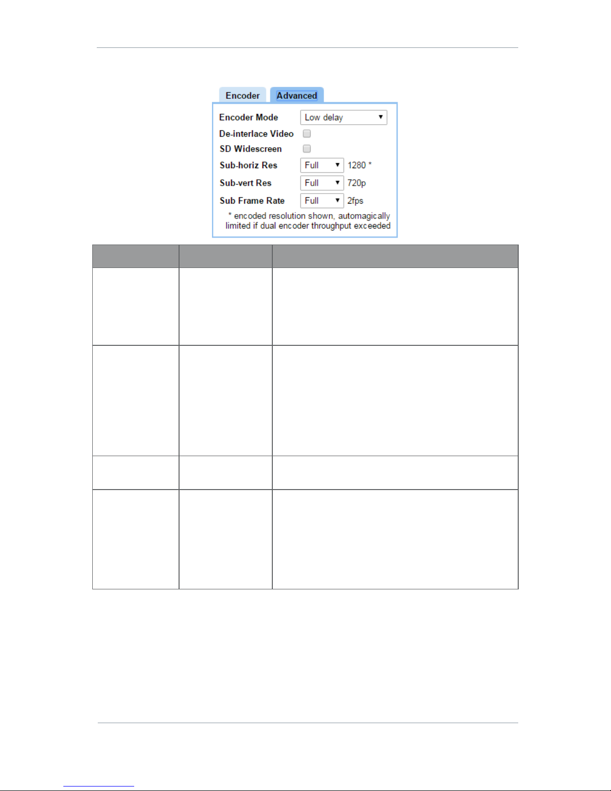
Advanced Encoder Settings
Property
Value
Description
Encoder Mode
Standard
Low Delay
Ultra Low Delay
Select the quantity of delay you can accept.
Standard delay provides higher picture quality at the
expense of delay.
Ultra Low Delay provides very low delay at the expense of
picture quality.
De-Interlace Video
Checkbox – set or
clear
If selected, this converts interlaced fields to a progressive
frame. This improves picture quality on PC monitor type
devices. Having a progressive type of image is also easier
to encode so you save bit rate too.
Use it when you wish to show video on a computer monitor
and save bit rate.
Don’t use it when you wish to keep vertical resolution or
interlaced field rate.
SD Wide Screen
Checkbox – set or
clear
If selected, this will change the display aspect ratio to wide
screen.
Sub-horiz Res
Full
3/4
2/3
1/2
1/4
This is the fraction of the horizontal resolution for whatever
format you have selected.
Let’s say you chose an HD 1080 format. This is actually
1920 x 1080 where 1920 is the horizontal resolution.
If you select Full then you’ll see all 1920 pixels, if you select
1/2 you’ll see a down-sampled picture which requires much
less bit-rate to encode.
Page 51
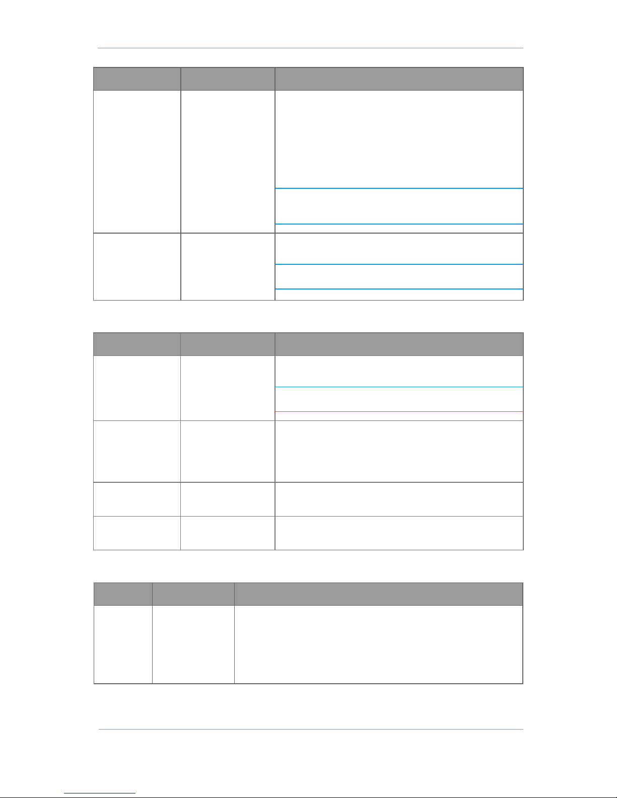
AEON Family User Guide
Commercial in Confidence
Video, Broadcast
100249
Revision: 1.0
Commercial in Confidence
Page 6-44
Property
Value
Description
Sub-vert Res
Full
1/2
1/4
This is the fraction of the vertical resolution for whatever
format you have selected.
Let’s say you chose an HD 1080 format. This is actually
1920 x 1080 where 1080 is the vertical resolution.
If you select Full then you’ll see all 1080 lines, if you select
1/2 you’ll see a down-sampled picture which requires much
less bit-rate to encode.
Note: Depending on the type of video content, when using a
sub-vertical resolution you may wish to enable the deinterlace option too.
Sub Frame Rate
Full
1/2
1/4
1/8
1/24
If full frame rate is giving unsatisfactory quality, you can
step this down until you get a satisfactory picture.
Note: Using a sub-frame rate will set the Encoder Mode to
Standard Delay.
Motion JPEG Pane
Property
Value
Description
Sub Sampling
Full
1/2
1/4
1/8
If full frame rate is giving unsatisfactory quality, you can
step this down until you get a satisfactory picture.
Note: Using a sub sampling rate will set the Encoding
Mode to Standard.
Picture Quality
0 to 100%
You can set a value to increase or reduce picture quality.
When you increase picture quality and the bitrate available
is limited, the Frame Rate could be reduced to keep the
stream running.
Frame Period
100ms
The frame refresh period for the streaming video used for
monitoring in milliseconds.
Event Overlay
Checkbox – set or
clear
If set, this produces a momentary pink overlay on the
MJPEG display when an event occurs.
Test Pattern Pane
Property
Value
Description
Generator
Control
Disabled
Force On
Auto Video/Audio
Auto Video
Auto Audio
AV Sync
The video output will default to this when there is no video input.
If Force on is selected, this will override the video input and will
make the test pattern the video output.
Page 52
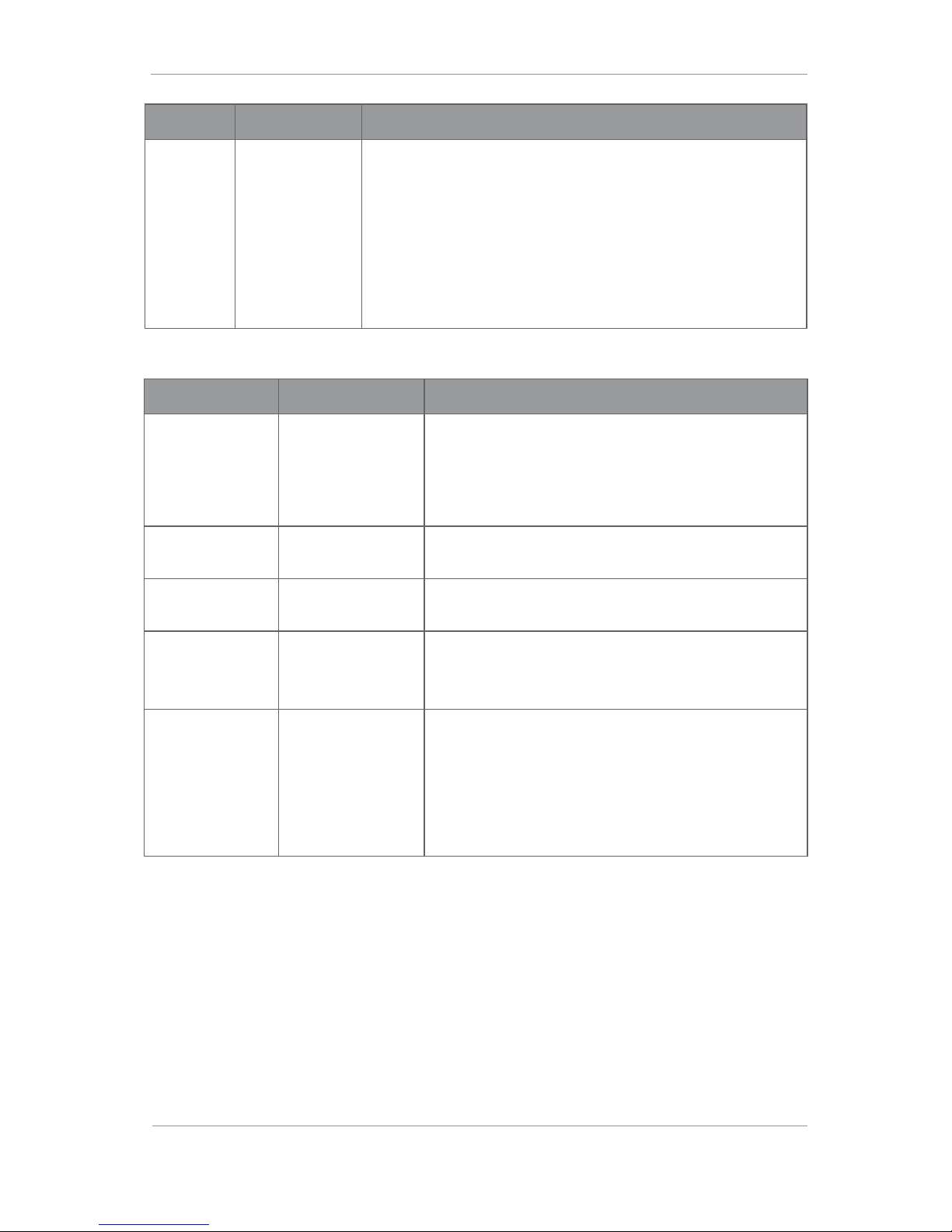
AEON Family User Guide
Commercial in Confidence
Video, Broadcast
100249
Revision: 1.0
Commercial in Confidence
Page 6-45
Property
Value
Description
Pattern
Mode
Black screen
Blue screen
Green screen
Cyan screen
Red screen
Magenta screen
Yellow screen
White screen
Static pattern
Moving pattern
This is what will appear on the screen in the event of no video input
or if Generator Control is set to Force On.
Motion Triggers
Property
Value
Description
Event Mode
Off
Brightness
Vectors
Vectors-Median
Hybrid
This sets the mode which will cause a trigger to occur.
Vectors-Median has improved noise filtering and Hybrid is
a combination of both motion vectors and brightness.
When you select an Event Mode, The Event Mask will
become active.
Event Action
None
Record
This will set the action to be taken when the trigger occurs.
Event Duration
Up to 59999 seconds
The length in seconds that the Event Action will occur when
an Event is triggered.
Event Threshold
Slider
Drag the slider to set.
This will control the sensitivity of the encoder to an event.
Extreme left is the least sensitive to the trigger event.
Event Mask
Video Overlay
This becomes active when you select an Event Mode.
Use the slider tool to increase or decrease the pixel size.
When you click on a pixel it becomes red. This will deselect
this part of the video from a trigger event.
Use the Set All or Clear All buttons to select or deselect all
the pixels.
Page 53
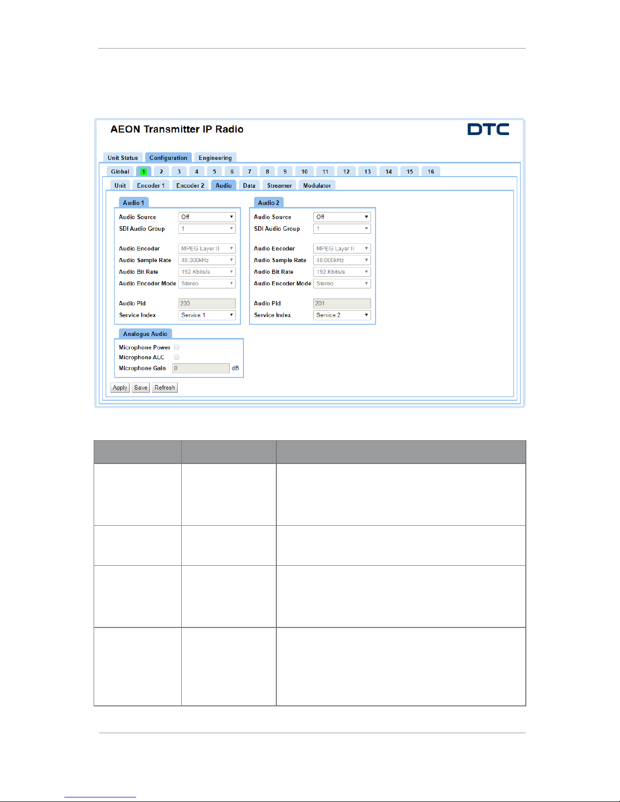
AEON Family User Guide
Commercial in Confidence
Video, Broadcast
100249
Revision: 1.0
Commercial in Confidence
Page 6-46
6.5 Configuration>Preset>Audio Tab
There are up to sixteen different preset Configurations that can be setup. In this example we are viewing
preset 1 which is highlighted with a green background to denote that it is active.
Audio Pane
Property
Value
Description
Audio Source
Off
Analogue
Embedded 1
Embedded 2
When Analogue is selected, the audio input cable can be
used for mono left, mono right or stereo pair.
When Embedded is selected, the audio is embedded in the
SDI video signal.
SDI Audio Group
1, 2, 3, 4
SDI provides 16 channels of embedded audio in eight pairs.
This should be left at default unless an advanced user.
Audio Encoder
MPEG Layer I
MPEG Layer II
MPEG Layer III (mp3)
You can select one of three modes to suit operating and
bandwidth requirements.
The higher the audio quality used the less the video
bandwidth available.
Audio Sample Rate
16.000kHz
22.050kHz
24.000kHz
32.000kHz
44.100kHz
48.000kHz
This is the MPEG audio encoding sample rate. Usually the
higher the number the better the audio quality.
Page 54

AEON Family User Guide
Commercial in Confidence
Video, Broadcast
100249
Revision: 1.0
Commercial in Confidence
Page 6-47
Property
Value
Description
Audio Bit Rate
Available rates
depend on current
audio encoder.
MPEG Layer I:
32-448kbits/s
MPEG Layer II:
32-384kbits/s
MPEG Layer III:
32-320kbits/s
This is the MPEG audio encoding bit rate.
Usually the higher the number the better the quality.
Audio Encoder
Mode
Stereo
Left Mono
Right Mono
Dual Mono
Select the audio mode you wish to use.
Dual Mono allows for different gain values on the left and
right channel. Stereo uses only one.
Audio Pid
32 to 8190
This sets the PID for the audio content in the Program. The
Audio PID is listed in the PMT (Section 0).
These can be edited but should be left to default unless an
advanced user.
Service Index
Service 1
Service 2
This links the audio channel to the Streamer service.
Analog Audio Pane
If the Audio Source is set to Analogue, these settings will apply.
Property
Value
Description
Microphone Power
Checkbox - set or
clear
If set, this will enable power to the microphone input at
approximately 3V (applicable for Electret microphones).
Microphone ALC
Checkbox - set or
clear
Automatic Level Control controls power to the speaker,
preventing overload. If set, this will enable the
microphone ALC on.
Microphone Gain
0 to 60
Used to set the audio gain applied to the audio input
signal.
0dB is no gain which is the default setting.
If you have low level audio sources you can wish to apply
more gain.
Page 55
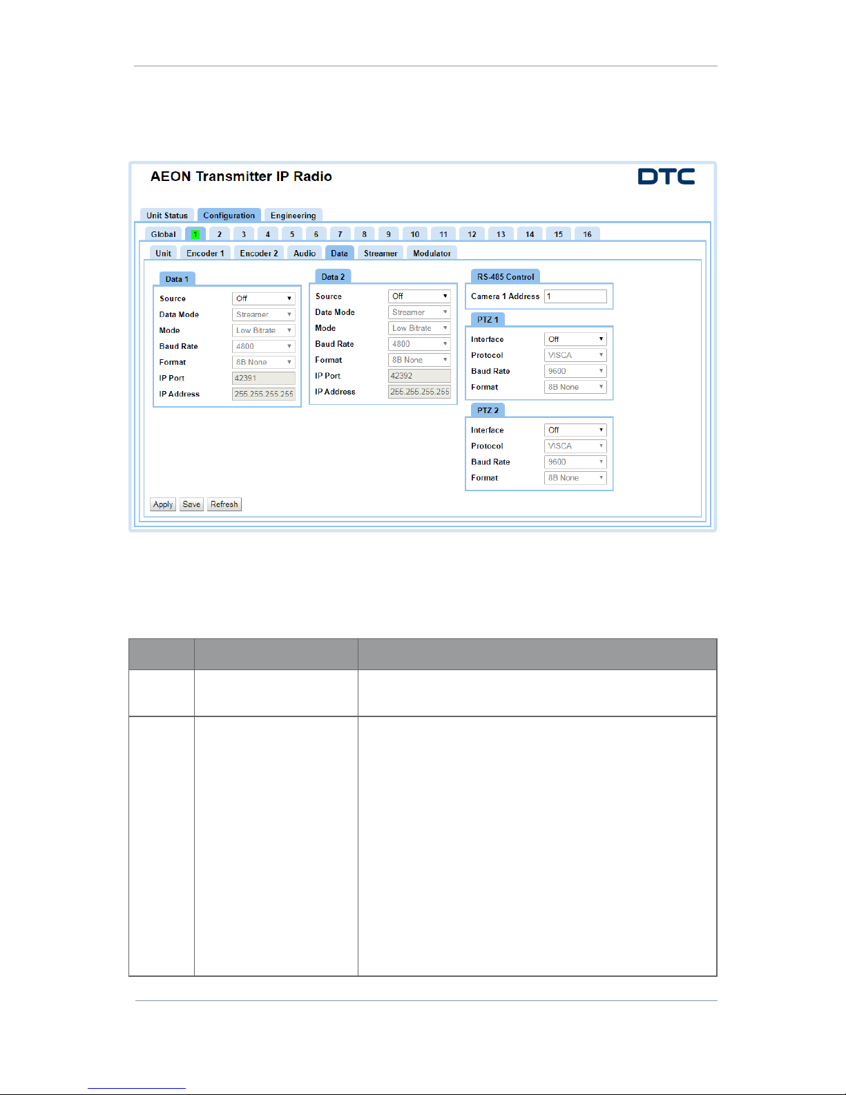
AEON Family User Guide
Commercial in Confidence
Video, Broadcast
100249
Revision: 1.0
Commercial in Confidence
Page 6-48
6.6 Configuration>Preset>Data Tab
There are up to sixteen different preset configurations that can be setup. In this example we are viewing
preset 1 which is highlighted with a green background to denote that it is active.
Data Pane
A remote data link may be setup and data packets added to the Service.
There are two sets of data parameters, Data 1 and Data 2. These are the data packets for Streamer Service
1 and 2.
Property
Value
Description
Source
Off
RS-485
This selects the serial interface for the transfer of data
between AEON Transmitter and a remote unit.
Data
Mode
Streamer
UDP
TCP Server
TCP Client
Streamer – When in Streamer mode, serial data will embedded
in the IP stream.
UDP - User Datagram Protocol is used to move data about the
network. The packets are sent out and the system does not
expect a reply. There is no way that the sending device can tell
if the data arrived at the destination.
TCP - Transmission Control Protocol is used to move data
about the network. The packets are sent out and the system
will expect a reply. Each message is acknowledged by the
destination device.
TCP Server/Client allows applications such as telnet to
connect to the port.
Setting one AEON Transmitter to TCP Server and one to TCP
Client allows data pipes to be formed.
Page 56
AEON Family User Guide
Commercial in Confidence
Video, Broadcast
100249
Revision: 1.0
Commercial in Confidence
Page 6-49
Property
Value
Description
Mode
Low bitrate
Low latency
Select Low latency to minimise delay at the expense of bitrate.
Baud
rate
1200 to 115200
The baud rate of the output.
Format
8B None, 8B Even, 8B Odd,
7B None, 7B Even, 7B Odd
The data and parity bit.
IP Port
42391
These set an IP Port to and from which the data will be
transferred.
The user can connect to the data port through Telnet by setting
the mode to TCP and the port number to 23.
The user can connect two data ports on different units by
setting UDP mode and using the aligning port numbers.
IP
Address
255.255.255.255
The IP address of the destination computer which wishes to
connect or all 255’s for any host.
These set an IP address to and from which the data will
transferred.
RS-485 Control Pane
Property
Value
Description
Camera 1 Address
0 to 255
The attached camera must be given a unique address
which the AEON Transmitter must match.
PTZ Pane
Property
Value
Description
Interface
Off
RS-485
The serial interface for the transfer of data between your
camera and the AEON Transmitter unit.
This will change where the PTZ commands go to on the
Camera Control connector.
Protocol
VISCA, Pelco-D
Control protocols for PTZ devices.
Baud rate
1200 to 115200
The baud rate of the output.
Data format
8B None, 8B Even, 8B Odd,
7B None, 7B Even, 7B Odd
The data and parity bit.
Page 57
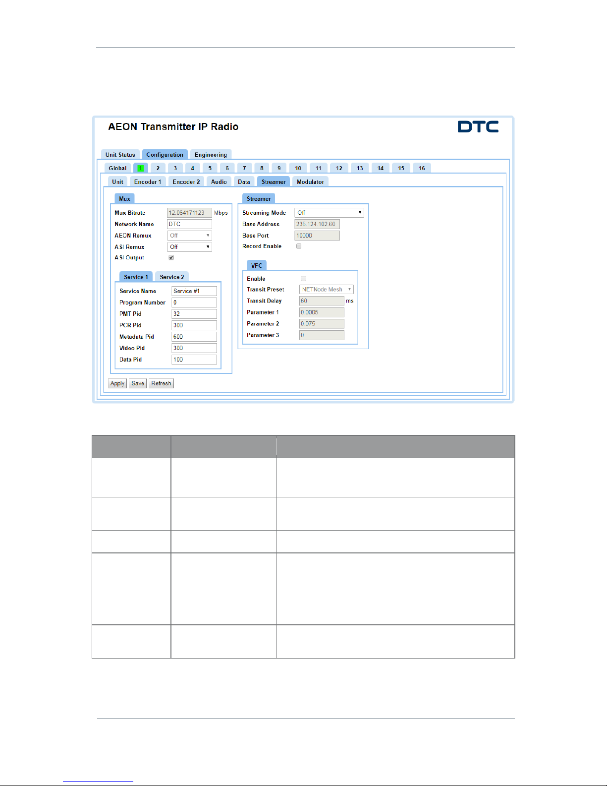
AEON Family User Guide
Commercial in Confidence
Video, Broadcast
100249
Revision: 1.0
Commercial in Confidence
Page 6-50
6.7 Configuration>Preset>Streamer Tab
There are up to sixteen different preset configurations that can be setup. In this example we are viewing
preset 1 which is highlighted with a green background to denote that it is active.
Mux Pane
Property
Value
Description
Mux Bitrate
Up to 50Mbits/s
The multiplexer bitrate for the service.
If the Modulation is set to off, this can be set manually.
Network Name
Up to 40 alphanumeric
characters
A name to identify the Mux. It will appear as the Publisher
in VLC.
AEON Remux
Off
This cannot be set when in SDR Dual encoder mode.
ASI Remux
Off
On
Relay
Off – No ASI.
On – Enables the re-multiplexing of an ASI input.
Relay – disables local services and only passes ASI.
See Notes at the bottom of the Table.
ASI Output
Set or clear
When set, the ASI output will contain the same content
sent over the modulator.
Page 58

AEON Family User Guide
Commercial in Confidence
Video, Broadcast
100249
Revision: 1.0
Commercial in Confidence
Page 6-51
Property
Value
Description
Service Name
Service #1 or characters
you choose
This is an identifier for the service in the Transport
Stream (TS). The TS can have many services.
The receiver must align with this name for the service to
be decoded.
Program Number
1, 2, etc.
A number to identify the Program. Transport Streams have
Programs, each Program is described by a PMT.
PMT Pid
32 to 8190
Each table or elementary stream in a transport stream is
identified by packet ID (PID).
The Program Map Table (PMT) contains information about
the Program. For each Program, there is one PMT.
These can be edited but should be left to default unless
an advanced user.
PCR Pid
32 to 8190
Each table or elementary stream in a transport stream is
identified by packet ID (PID).
The Program Clock Reference (PCR) is used to sync the
audio and video. The PCR PID is listed in the PMT.
These can be edited but should be left to default unless
an advanced user.
Metadata Pid
32 to 8190
Each table or elementary stream in a transport stream is
identified by packet ID (PID).
This sets the PID for the metadata associated with the
Program. The Metadata PID is listed in the PMT.
These can be edited but should be left to default unless
an advanced user.
Video Pid
32 to 8190
Each table or elementary stream in a transport stream is
identified by packet ID (PID).
This sets the PID for the video content in the Program. The
Video PID is listed in the PMT.
These can be edited but should be left to default unless
an advanced user.
Data Pid
32 to 8190
The packet identifier for the data. The Data PID is listed in
the PMT.
These can be edited but should be left to default unless
an advanced user.
Note 1: The mux bitrate must be equal to or greater than the total bit rate of services and inputs. If the total
bit rate exceeds the mux bitrate the output stream won’t work.
Note 2: If you set ASI Remux to Relay it disables the video source for that channel. You must switch ASI
Remux Off when you want to reselect a video source.
Page 59

AEON Family User Guide
Commercial in Confidence
Video, Broadcast
100249
Revision: 1.0
Commercial in Confidence
Page 6-52
Streamer Pane
Property
Value
Description
Streaming Mode
Off
UDP
RTSP Unicast
RTSP Multicast
RTP
RTP-Z
Select the streaming mode you wish to operate with.
Streams can be played back using VLC or Domo Video
Player (requires a license).
Note: RTP-Z is DTC’s compressed RTP. You will need
Domo Video Player to run streams using this protocol. If
you select RTP-Z, VFC Options will become available.
Base Address
For example:
237.103.227.228
This enables you to change the address used by the unit
for streaming. The default value is random to make sure
different AEON Transmitter have different multicast
addresses.
Base Port
10000 or above
UDP uses port numbers in the header to direct traffic
around the network.
A good rule is to use numbers above 10000 to avoid
conflict with existing services.
When you set up a port number on several computers on a
network they will all listen for packets directed to that
port.
Record Enable
Set or clear
When you select this box, the video will be recorded to the
built in SD card.
VFC Enable
Set or clear
If set, this enables Video Flow Control (VFC) when
streaming in RTP-Z.
VFC allows the video bitrate to be varied depending on the
bandwidth available. This prevents corruption of the video
when bandwidth drops and allows the picture quality to
adapt accordingly.
Note: VFC is a PID Controller. VFC Parameters 1, 2 and 3
correspond with the Proportional, Integral and Derivative
terms of the control loop.
VFC Transit Preset
Custom
NETNode Mesh
If you choose Custom, you can manually select values for
Transit Delay and Parameters.
Choose one of the Presets to autofill the remaining
settings.
VFC Transit Delay
Up to 2000ms
Too low a value will drop the bitrate, too high a value will
increase latency and corrupt the video. In most cases the
default value will operate well.
The VFC operates by monitoring the latency from the video
encoder to the endpoint. The system tries to maintain the
round trip of the Transit Delay.
VFC Param1
0 to 1
Can be up to six decimal places.
This corresponds with the VFC Proportional term.
Page 60

AEON Family User Guide
Commercial in Confidence
Video, Broadcast
100249
Revision: 1.0
Commercial in Confidence
Page 6-53
Property
Value
Description
VFC Param2
0 to 1
Can be up to six decimal places.
This corresponds with the VFC Integral term.
VFC Param3
0 to 1
Can be up to six decimal places
This corresponds with the VFC Derivative term.
Page 61
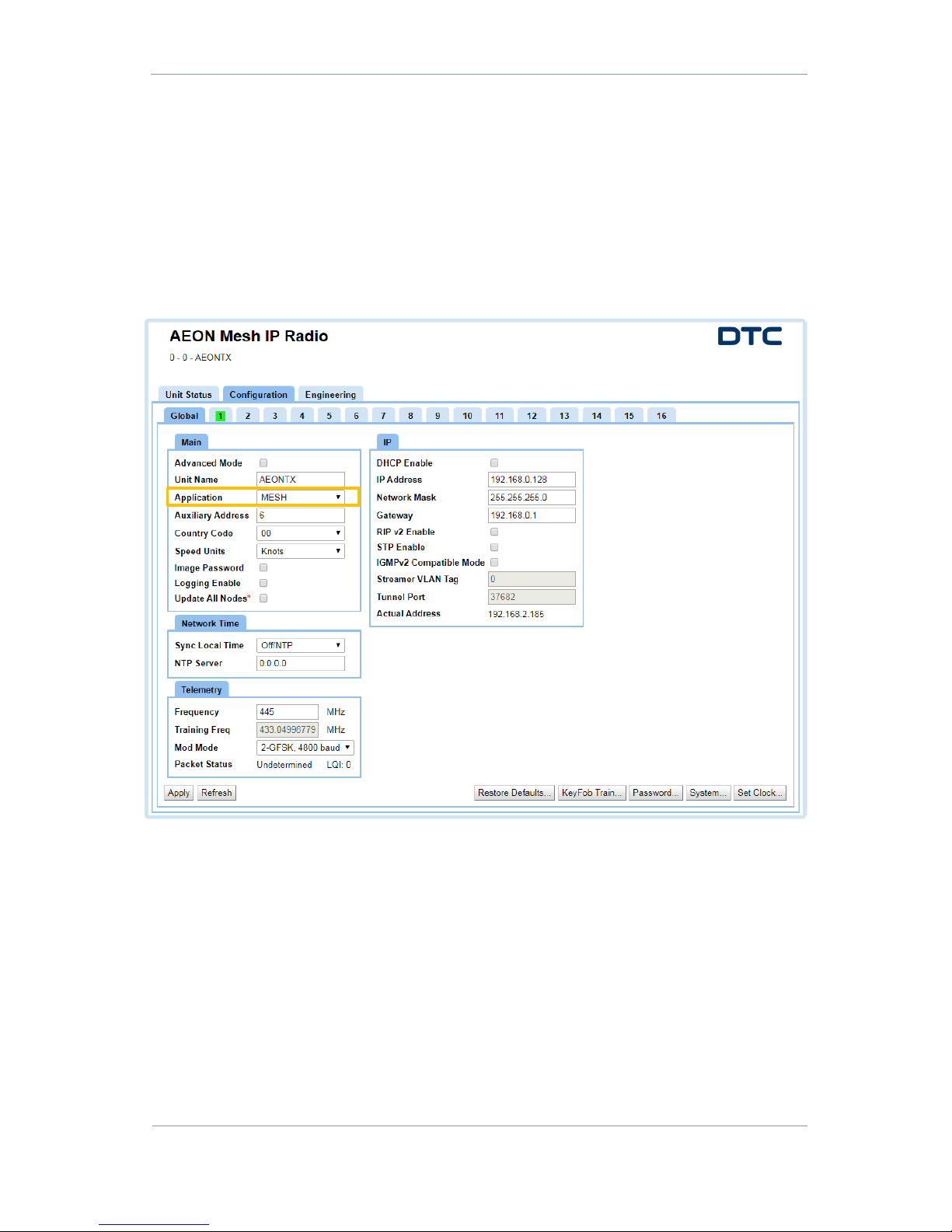
AEON Family User Guide
Commercial in Confidence
Video, Broadcast
100249
Revision: 1.0
Commercial in Confidence
Page 7-54
7. AEON-MESH Web Browser Operation
7.1 Introduction
This section will only show the configurations which require explanation as a result of this configuration
and are not detailed in the NETNode Phase 5 Software Guide or in previous sections of this document.
For full details of Mesh operation, refer to DTC document NETNode Phase 5 Software Guide which has
instructions which are compatible with the AEON-MESH.
When MESH is selected as the Encoder Config in the Configuration>Global tab, some of the views and
selections will change accordingly.
Page 62
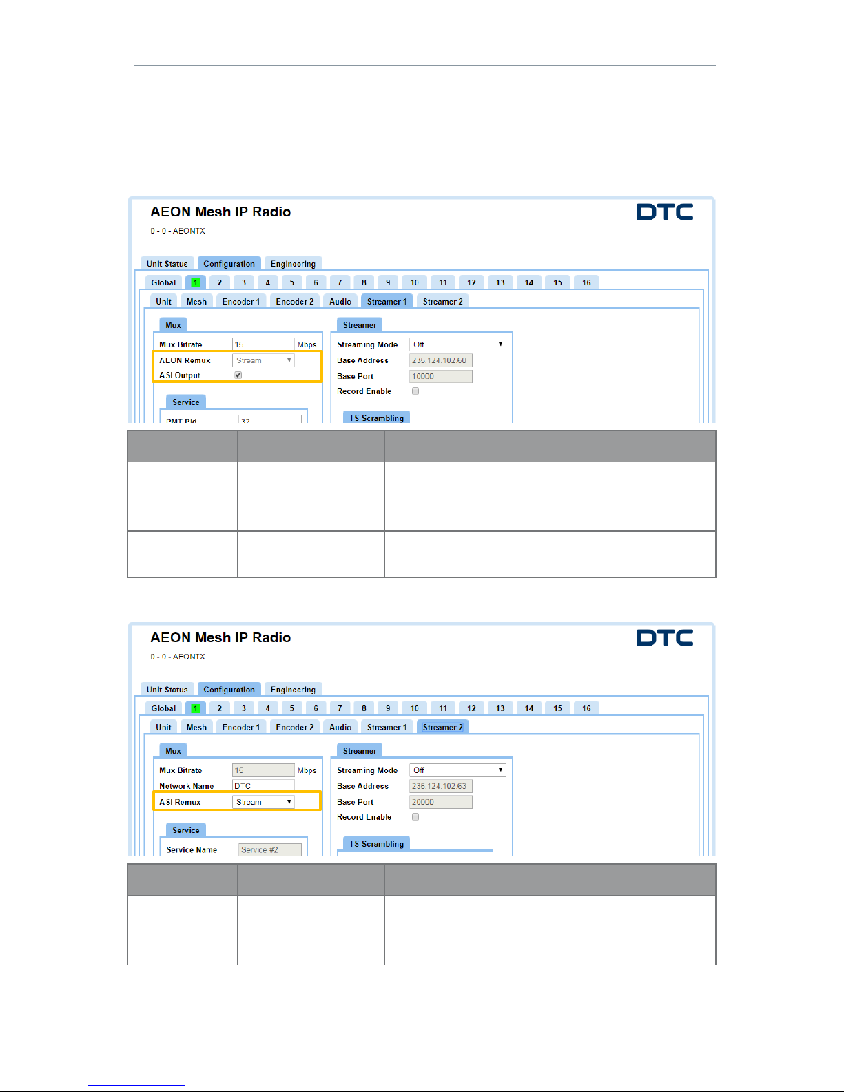
AEON Family User Guide
Commercial in Confidence
Video, Broadcast
100249
Revision: 1.0
Commercial in Confidence
Page 7-55
7.2 AEON-MESH with AEON Encoder
When AEON-MESH is configured as an AEON encoder in the Configuration>Preset>Unit tab, the following
settings for the Streamer 1 and Streamer 2 tabs needs to be explained.
Streamer 1
Property
Value
Description
AEON Remux
Stream
Set to Stream by default.
This means that what is being encoded by the AEON will
appear on the Streamer 1 output.
ASI Output
Set or clear
When set, the ASI output will contain the same content
sent over Streamer 1.
Streamer 2
Property
Value
Description
ASI Remux
Off
Stream
Set to Stream by default.
This means that the remuxed ASI input will appear on the
Streamer 2 output.
Page 63
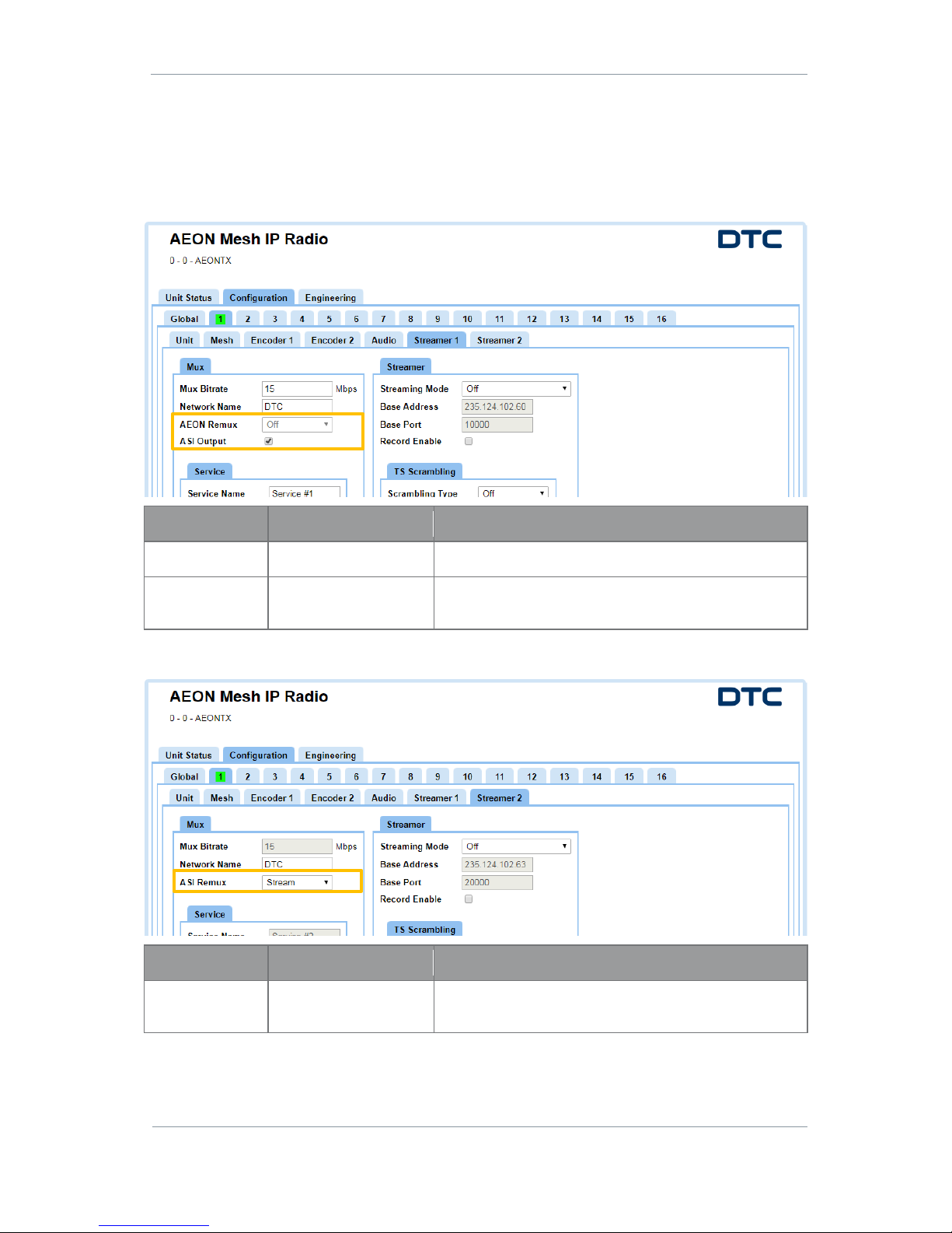
AEON Family User Guide
Commercial in Confidence
Video, Broadcast
100249
Revision: 1.0
Commercial in Confidence
Page 7-56
7.3 AEON-MESH with SDR Dual Encoder
When AEON-MESH is configured as an SDR Dual encoder in the Configuration>Preset>Unit tab, the
following settings for the Streamer 1, Streamer 2 and Encoder tabs needs to be explained.
Streamer 1
Property
Value
Description
AEON Remux
Off
Set to Off by default.
ASI Output
Set or clear
When set, the ASI output will contain the same content
sent over Streamer 1.
Streamer 2
Property
Value
Description
ASI Remux
Off
Stream
When set to Stream, this means that the remuxed ASI
input will appear on the stream 2 output.
Page 64
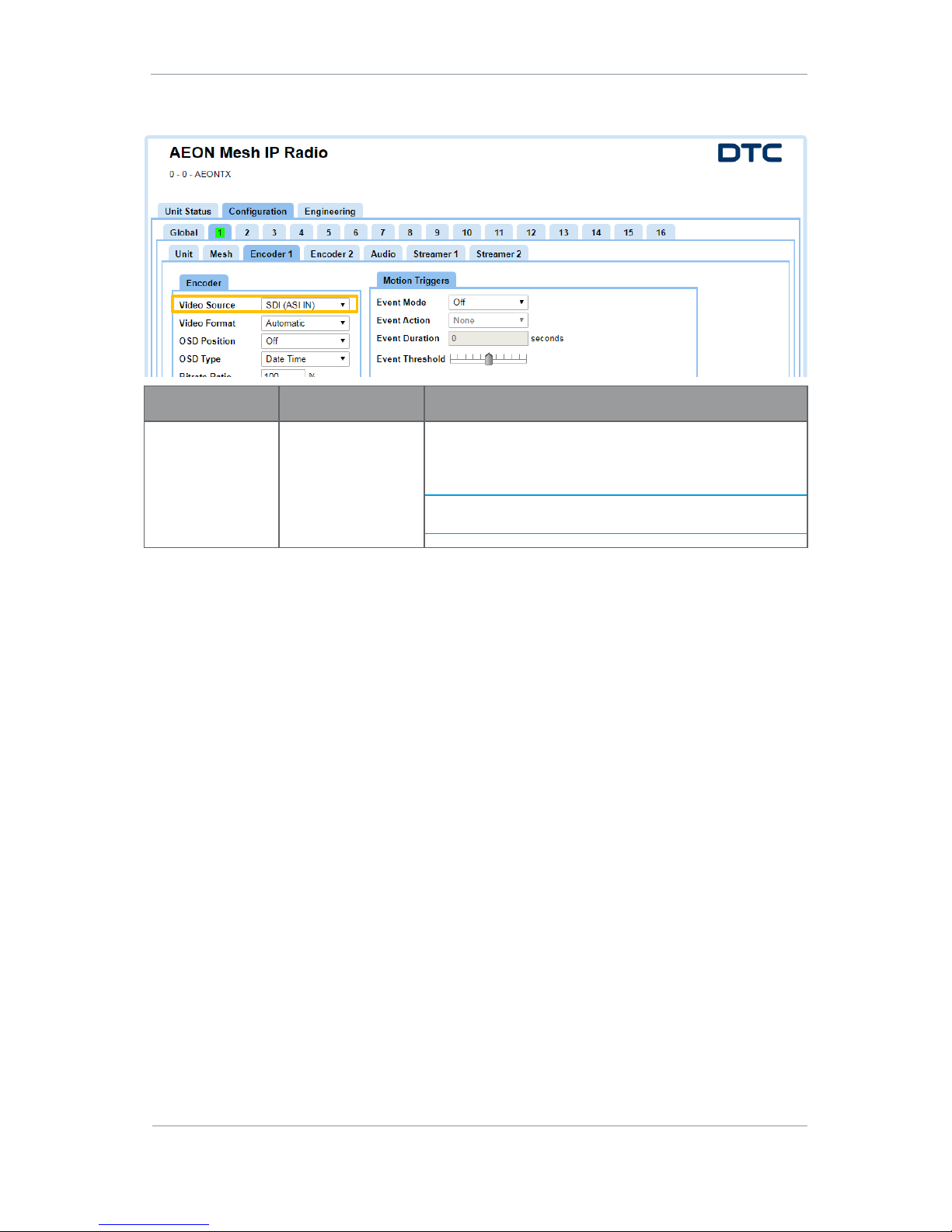
AEON Family User Guide
Commercial in Confidence
Video, Broadcast
100249
Revision: 1.0
Commercial in Confidence
Page 7-57
Encoder
Property
Value
Description
Video Source
Off
SDI (ASI IN)
MJPEG 1 (USB)
Select the video input source.
The physical port on the AEON Transmitter is indicated in
brackets.
Note: SDI input will only work when ASI IN is not being used
for Remux. See above.
Page 65
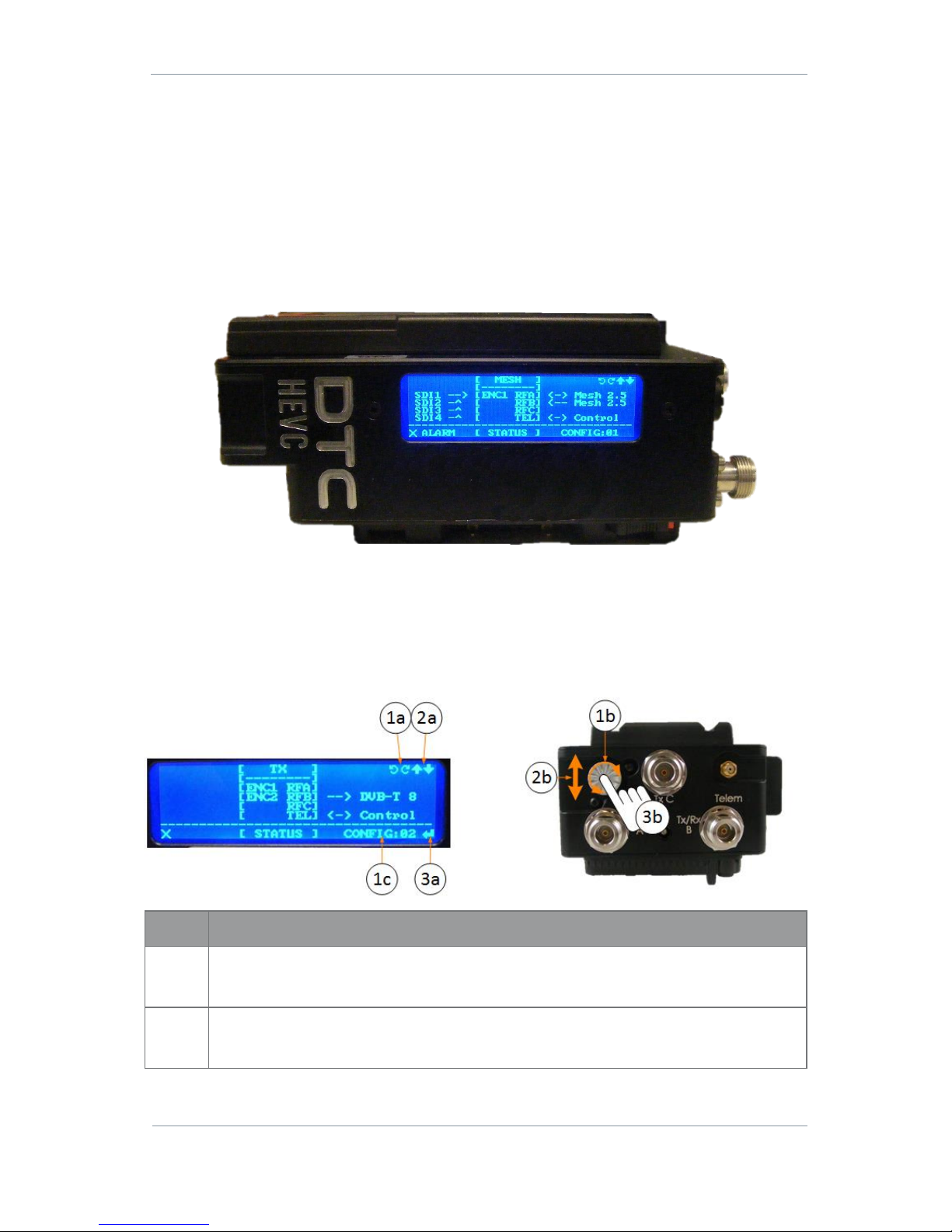
AEON Family User Guide
Commercial in Confidence
Video, Broadcast
100249
Revision: 1.0
Commercial in Confidence
Page 8-58
8. AEON Transmitter LCD Display Operation
8.1 Overview
When in deployment, the AEON Transmitter may be controlled and monitored via the LCD display.
The LCD display will go into sleep mode after approximately one minute, to wake the LCD simply press or
move the control button in any direction.
When the LCD wakes up, the status view will be displayed.
8.2 Icons and Controls
The LCD display is controlled by the navigation button on the top panel. The LCD display has some icons
that let you know which button movements are active.
Item
Description
1a/1b
The rotation icons (1a) indicate that the button rotation (1b) is active.
When in the status view, rotation will change the config selection (1c).
2a/2b
The arrow icons (2a) indicate that the button up/down movement (2b) is active.
When in the status view, button up/down will change the status pages.
Page 66
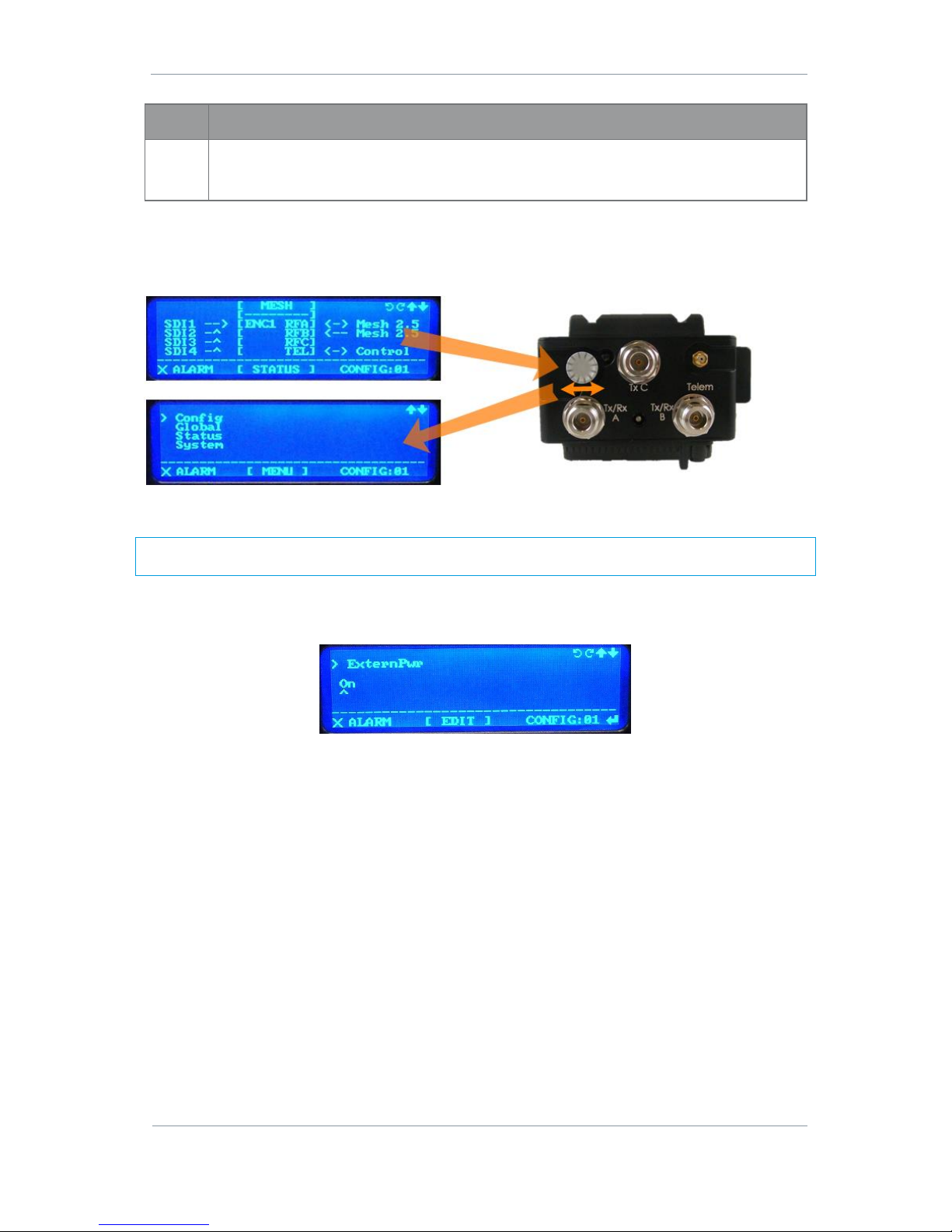
AEON Family User Guide
Commercial in Confidence
Video, Broadcast
100249
Revision: 1.0
Commercial in Confidence
Page 8-59
Item
Description
3a/3b
The enter icon (3a) indicates that the button press (3b) is active.
When in the status view, press the button to enter the config selection.
8.3 Navigating the Menu
From the status page, move the navigation button left or right, to view the menu list, see below.
From this page, the menu structure can be navigated to a higher or lower level by moving the button left or
right.
Note: Always pay attention to the icons that are displayed to inform you of what button actions are
available.
When you navigate to a parameter that you wish to edit, you will find that button up/down and rotation will
both change the selection. When the desired selection has been made, use the button press to save the
value.
Page 67
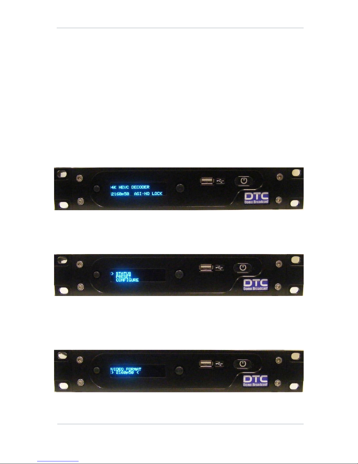
AEON Family User Guide
Commercial in Confidence
Video, Broadcast
100249
Revision: 1.0
Commercial in Confidence
Page 9-60
9. AEON Decoder/Encoder Operation
9.1 Introduction
AEON Decoders and Encoders are controlled from the front panel OLED display.
This section explains operation to enable the user to customise the device for specific requirements.
See Section 3.3 for hardware connectivity.
9.2 OLED Display
Boot Up
The OLED display shows status information and allows the user to make some necessary configurations.
After initialisation on boot up, the status page will be displayed. The status page displays current settings
and video input information.
The Left Button
Push the left button to enter the display menu.
From the top menu level the left button is inactive, but from lower menu levels the left button operates as
an escape to the previous display.
The Right Button
The right button will navigate the menu list up and down and push to select.
When a parameter has been selected for edit, the right button can be used again to change the value by
moving up/down, or left/right to change the location of the cursor when editing a string value.
Press to save the setting.
Page 68

AEON Family User Guide
Commercial in Confidence
Video, Broadcast
100249
Revision: 1.0
Commercial in Confidence
Page 9-61
9.3 Configurable Values
The AEON Encoder/Decoder is currently able to configure these values:
Property
Value
Description
Video Format
480i59, 480p59
576i50, 576p50
720p50, 720p59, 720p60
1080i50, 1080i59, 1080i60
1080p23, 1080p24, 1080p25,
1080p29, 1080p30
1080psf23, 1080psf24,
1080psf25, 1080psf29,
1080psf30
1080p50, 1080p59, 1080p60
2160p23, 2160p24, 2160p25,
2160p29, 2160p30, 2160p50,
2160p59, 2160p60
Select the video format for the system.
Sample Format
SQD
2SI
Square Division – each 3G-SDI link contains one
quarter of the original image.
2 Sample Interleave (2SI) – each 3G-SDI link
contains a full image at 1/4 resolution.
Note: The Decoder outputs currently only support
3G-SDI Level A signals.
Video PID
Audio PID
PCR PID
PMT PID
SIT PID
Variable
These values must match the PIDs being sent by
the AEON transmitter.
IP Address
User defined or DHCP
Change the IP address if DHCP has been disabled.
DHCP Mode
On
Off
Our devices are shipped to you with the DHCP
setting enabled. This means that if the AEON
decoder is connected to a network which is
administered by a DHCP server, an IP address will
be automatically allocated to it.
If you are unsure about your server settings, check
with your Network Administrator.
Page 69
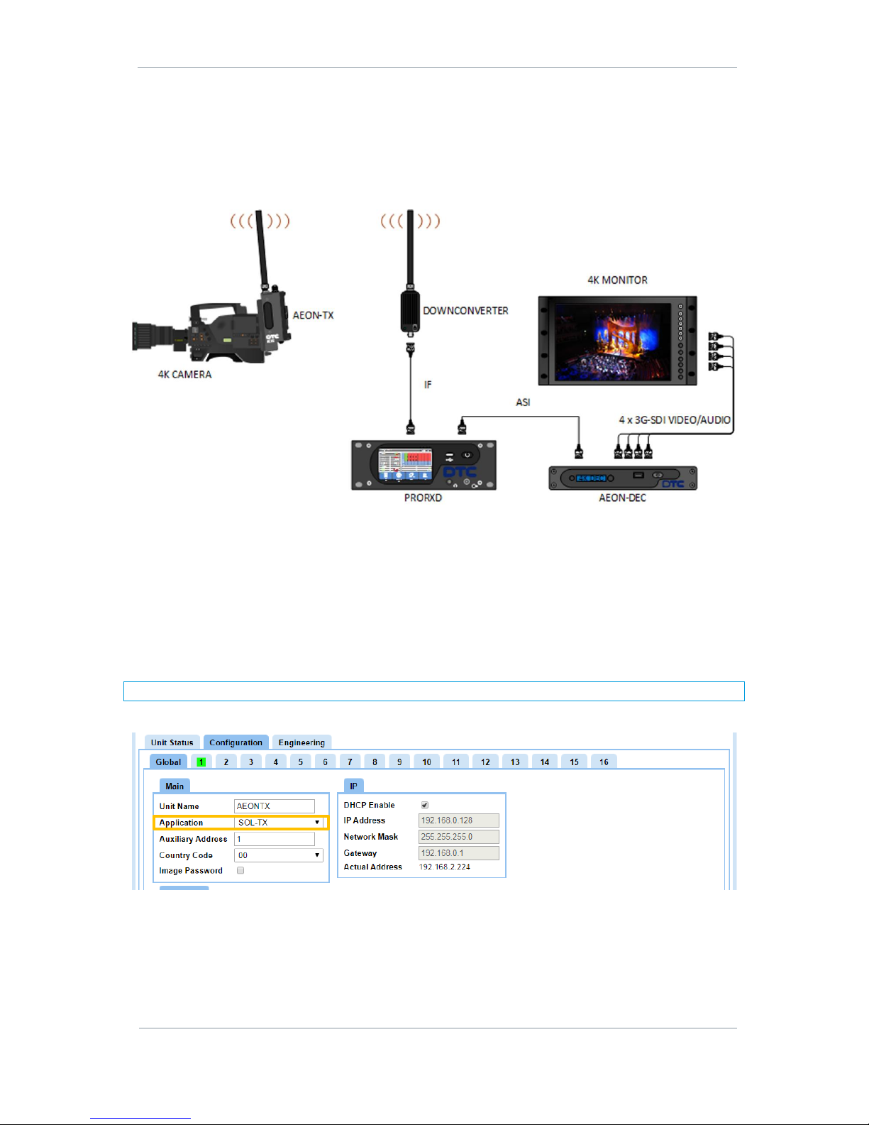
AEON Family User Guide
Commercial in Confidence
Video, Broadcast
100249
Revision: 1.0
Commercial in Confidence
Page 10-62
10. Example Applications
10.1 Single AEON 4K HEVC Encoder
Setup
Figure 10-1 4K HEVC Video
Figure 10-1 is an example setup for an AEON Transmitter fitted to a 4K video camera. The COFDM
transmission is received by a PRORXD and the ASI output is passed to the AEON Decoder. The decoded 4K
video is output as 4 x 3G-SDI video to a monitor for viewing.
The PRORXD will need to be setup in accordance with the PRORXD Broadcast Receiver User Guide.
AEON-TX Configuration
There are some basic configurations that will have to be made to ensure a successful transmission.
Note: If changes are needed, ensure that the Apply button is clicked to save the changes.
On the Global tab ensure that the Application is set to SOL-TX.
Page 70
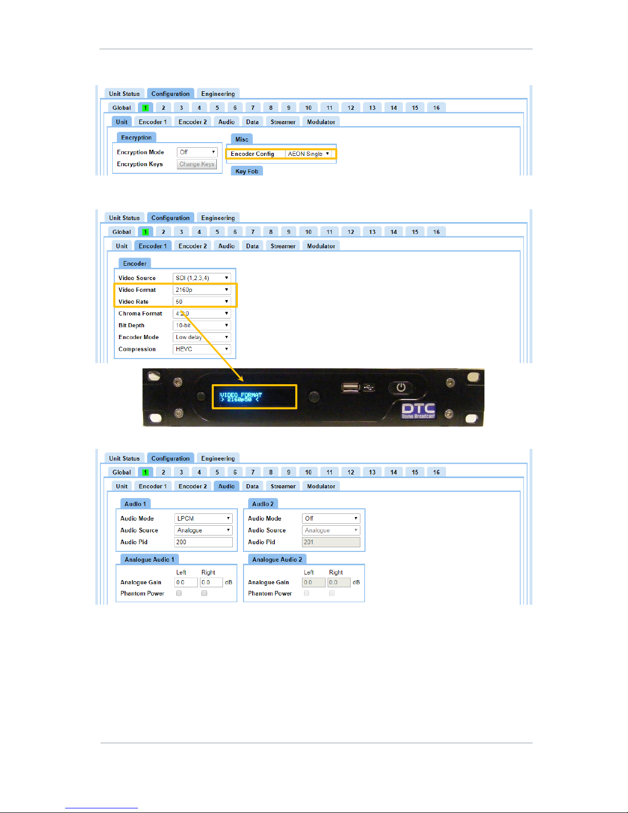
AEON Family User Guide
Commercial in Confidence
Video, Broadcast
100249
Revision: 1.0
Commercial in Confidence
Page 10-63
On the Unit tab ensure the Encoder Config is set to AEON Single.
On the Encoder tab set the video input encoding configurations. The Video Format and Video Rate must be
matched by the AEON Decoder.
On the Audio tab set up the audio input configurations, if applicable.
Page 71
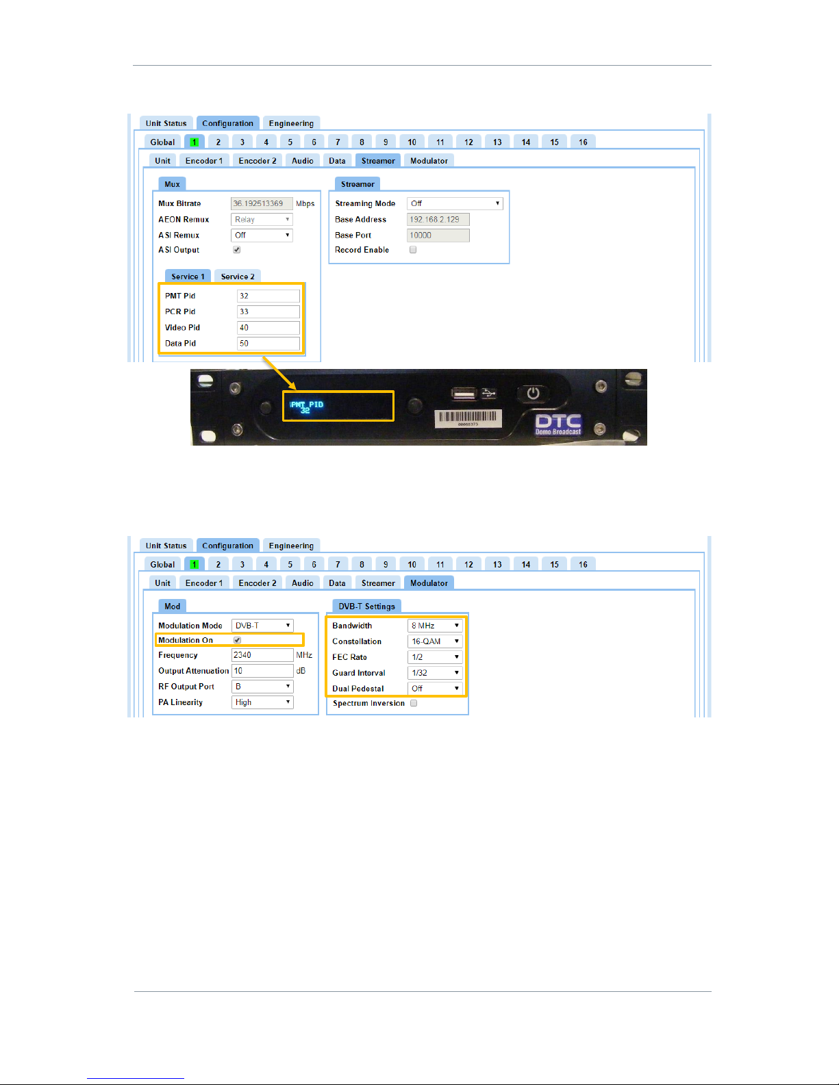
AEON Family User Guide
Commercial in Confidence
Video, Broadcast
100249
Revision: 1.0
Commercial in Confidence
Page 10-64
Ensure the AEON Decoder PIDs match the settings in the Streamer tab.
On the Modulator tab set up the modulation parameters, ensuring the correct Modulation Mode, Frequency
and Bandwidth requirements for the system. These settings must be matched at the PRORXD receiver.
Set the Modulation On checkbox to turn the RF power on.
Recommended DVB-T Settings for optimum video:
HD 1080p50/59 – 16-QAM, FEC 1/2
HD 1080p50/59 with LPCM audio – 16-QAM, FEC 2/3
Ultra HD 2160p50/59 – 16-QAM, FEC 1/2 or 2/3, Dual Pedestal enabled
The PRORXD Receiver should lock to the transmission and the demodulated ASI output passed to the AEON
Decoder. The Decoder OLED display should show ASI: Lock and the 4 x 3G-SDI output is available at the
Decoder for onward process.
Page 72
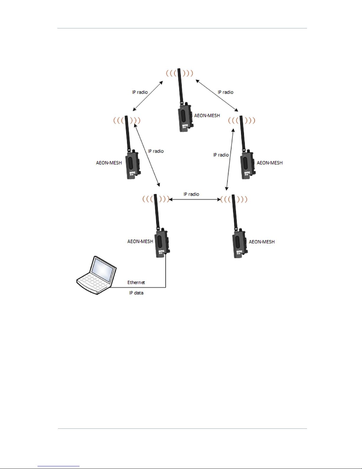
AEON Family User Guide
Commercial in Confidence
Video, Broadcast
100249
Revision: 1.0
Commercial in Confidence
Page 10-65
10.2 MESH Application
Setup
Figure 10-2 IP Mesh Radio
Figure 10-2 is an example setup of AEON Transmitters configured in an IP Mesh network. The network is a
fluid, self-healing Mesh of up to 16 nodes on a single transmit frequency. The IP data can be passed
onwards to a LAN or monitored on a laptop or PC.
For full details of Mesh operation, refer to DTC document NETNode Phase 5 Software Guide which has
instructions which are compatible with the AEON-MESH.
Page 73
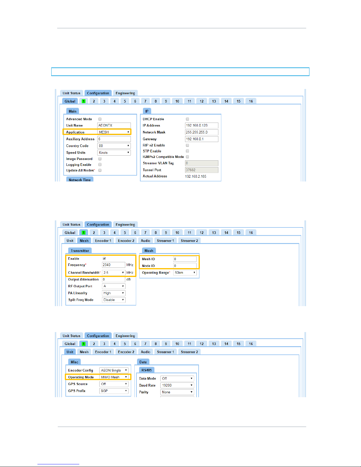
AEON Family User Guide
Commercial in Confidence
Video, Broadcast
100249
Revision: 1.0
Commercial in Confidence
Page 10-66
AEON-MESH Configuration
There are some basic configurations that will have to be checked and set as appropriate to ensure a
successful transmission.
Note: If changes are needed, ensure that the Apply button is clicked to save the changes.
On the Global tab ensure that the Application is set to MESH and configure the IP settings for the network.
On the Mesh tab set up the modulation parameters, ensuring the correct Frequency and Channel
Bandwidth requirements for the system.
The Mesh ID should match for all Nodes in a Mesh network but the Node ID must be unique from 0 to 16.
Set the Transmitter Enable checkbox to turn the RF power on.
Some consideration will need to be made to the Unit tab Operating Mode settings when transmitting 4K
quality video as it will be necessary to put the unit into MIMO Mesh mode in order achieve the data
requirements.
Page 74
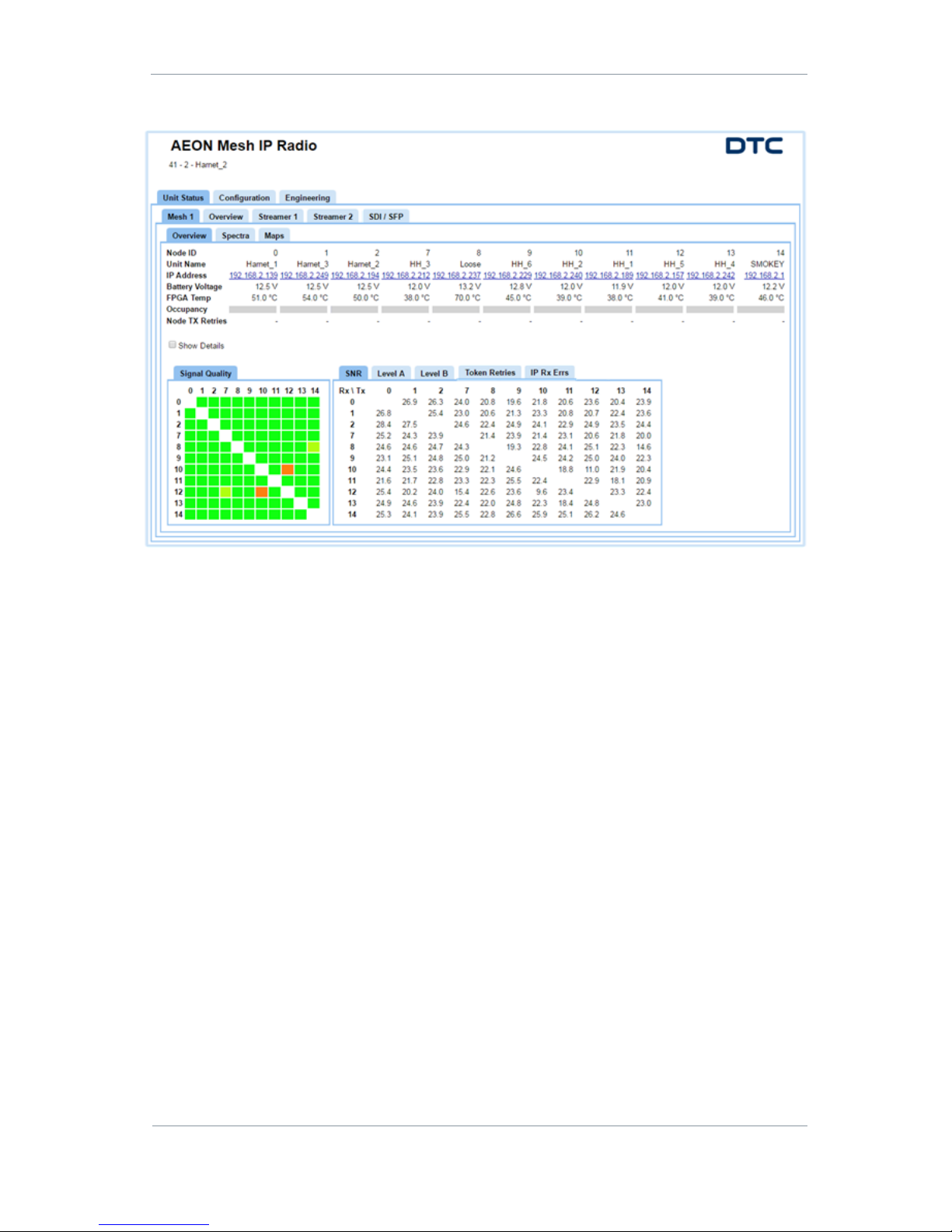
AEON Family User Guide
Commercial in Confidence
Video, Broadcast
100249
Revision: 1.0
Commercial in Confidence
Page 10-67
The AEON Mesh can be viewed in the Unit Status>Mesh>Overview page.
Page 75
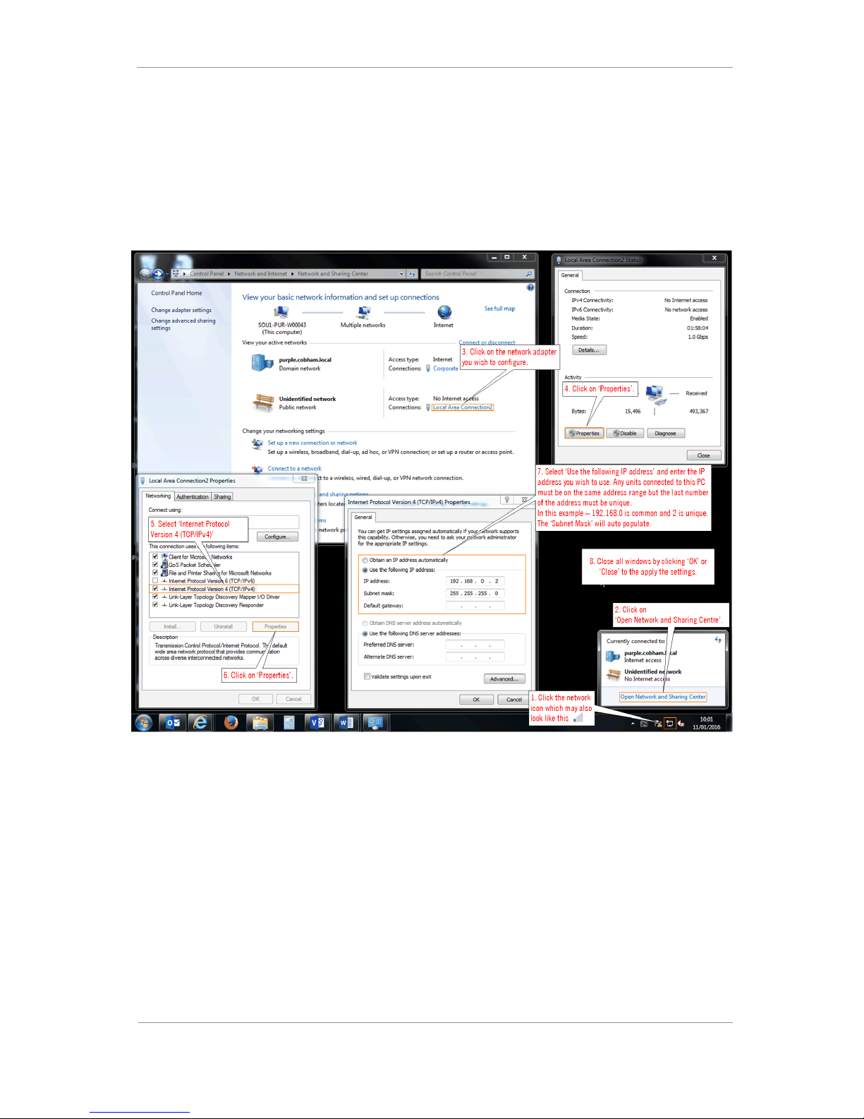
AEON Family User Guide
Commercial in Confidence
Video, Broadcast
100249
Revision: 1.0
Commercial in Confidence
Page 11-68
11. Appendix A – Reference Material
11.1 How to Configure a PC IP Address
The following guide will tell you how to configure your PC or laptop IP address so that it matches the IP
address range of the unit you are connected to. This is important because if they don’t match, you will not
be able to communicate with your device.
The IP address range given in this example is a good one to use if you are unsure.
Figure 11-1 How to configure a PC IP address
Page 76
AEON Family User Guide
Commercial in Confidence
Video, Broadcast
100249
Revision: 1.0
Commercial in Confidence
Page 11-69
11.2 AEON Transmitter Pinouts
CAMERA
Circular Hirose 10-way – HR10A-10R-10P (73)
Pin
Function
1
RS422 TX (H)
2
RS422 TX (C)
3
RS422 RX (H)
4
RS422 RX (C)
5
GND
6
RS232 TX
7
RS232 RX
8
N/C
9
N/C
10
GND
Tally
OB Lemo 5-way – EGG.0B.305.CLL
Pin
Function
1
GND
2
VBATT Out
3
RED 4 GREEN
5
N/C
DATA
OB Lemo 4-way – EEA.0B.304.CLL
Pin
Function
1
DATA_TX_RS232
2
DATA_RX_RS232
3
PA_TDD
4
GND
Page 77
AEON Family User Guide
Commercial in Confidence
Video, Broadcast
100249
Revision: 1.0
Commercial in Confidence
Page 11-70
Audio 1 and 2
OB Lemo 5-way – EEA.0B.305.CLL
Pin
Function
1
AUD_IN_L+
2
AUD_IN_L-
3
GND
4
AUD_IN_R+
5
AUD_IN_R-
Power
OB Lemo 4-way – EEG.0B.304.CLL
Pin
Function
1
VIN
2
VIN
3
GND
4
GND
Page 78
AEON Family User Guide
Commercial in Confidence
Video, Broadcast
100249
Revision: 1.0
Commercial in Confidence
Page 11-71
11.3 AEON Decoder/Encoder Pinouts
RS-232
Pin
Function
1
N/C
2
RS232 TX
3
RS232 RX
4
N/C 5 GND 6 N/C
7
N/C
8
N/C 9 N/C
Audio Inputs
OB Lemo 5-way – EEA.0B.305.CLL
Pin
Function
1
AUD_IN_L+
2
AUD_IN_L-
3
GND
4
AUD_IN_R+
5
AUD_IN_R-
Audio Outputs
OB Lemo 5-way – EEA.0B.305.CLL
Pin
Function
1
AUD_OUT_L+
2
AUD_OUT_L-
3
GND
4
AUD_OUT_R+
5
AUD_OUT_R-
Page 79

AEON Family User Guide
Commercial in Confidence
Video, Broadcast
100249
Revision: 1.0
Commercial in Confidence
Page 12-72
12. Appendix B – Getting Technical Support
12.1 Documentation and Software
It is DTC’s practice to make the majority of our latest user guides and software available to customers
online, by using our WatchDox facility. To access this site please contact your Account Manager or send a
request to [email protected].
You will be sent a link where you can login and create your own password followed by a confirmation email.
Once you have done this you will then be able log into your account.
12.2 Repairs
Do not attempt any repair, contact DTC Technical Support.
12.3 Contact Technical Support
The Technical Support team can be accessed by one of the following:
Post: DTC – Solent, Fusion 2, 1100 Parkway, Solent Business Park, Whiteley, Hampshire, PO15 7AB,
England
Phone: +44 1489 884 550. Office hours: 0900-1700 UK time excluding holidays
Email: [email protected] (no restricted content)
We undertake to get a first response to you in less than one working day and a progress update at least
every two weeks.
12.1 Using the DTC RMA Service
If there is a problem and all troubleshooting steps have been unsuccessful, you may need to contact DTC for
Return Material Authorisation (RMA) service.
Step 1: Email DTC
To return something to Solent please Email [email protected]. We will then send you
an RMA request form to complete and return. We’ll then send you an RMA number and shipping
instructions.
Step 2: Save your Personal Kit
Remove all personal kit or media from the device.
Step 3: Pack the Unit
Use the original shipping container and packing materials if possible.
If the original packing materials are not available, wrap the equipment with soft material (e.g. PU/PE form)
then put the wrapped equipment into a hard cardboard shipping box.
Page 80

AEON Family User Guide
Commercial in Confidence
Video, Broadcast
100249
Revision: 1.0
Commercial in Confidence
Page 12-73
Step 4: Prepare an Information Sheet
Include a sheet with the following information.
Note: Please keep a copy of this sheet for your records.
Name
Address
Unit serial number
Date of purchase or the original invoice number
Date of failure
A detailed description of the problems you have encountered
A list of the hardware/software configuration if applicable
Step 5: Put the RMA Number on the Box
Clearly mark the outside of the shipping box with the RMA number. If an RMA number is not present on the
shipping box, receiving will be unable to identify it and it might be returned.
Step 6: Send the Box to DTC
Send the box using your normal shipping process.
Page 81

AEON Family User Guide
Commercial in Confidence
Video, Broadcast
100249
Revision: 1.0
Commercial in Confidence
Page 13-74
13. Appendix C – Cautions and Approvals
13.1 Cautions and Warnings
These cautions and warnings may or may not apply to your installation. However, we would ask that you
read them to assess their relevance.
Area
Note
Enclosures
Do not remove any factory installed screws or fastenings. Damage to the units
may result and void any warranties.
Only authorised, trained personnel should open the product. There are no
functions that required the user to gain access to the interior of the product.
There are no user serviceable parts inside.
Environment
The equipment should not be used in hazardous or corrosive atmospheres. Users
are reminded of the necessity of complying with restrictions regarding the use of
radio devices in fuel depots, chemical plants and locations where explosives are
stored and/or used.
Power supply
Ensure that the power supply arrangements are adequate to meet the stated
requirements of each product. Observe all electrical safety precautions.
Electro static
discharge (ESD)
precautions
ESD guidelines must be followed when necessary.
Lightning strike
There is a risk of lightning strike to antennas. The equipment should not be
assembled in an area at the time of lightning activity. Antennas should be
adequately protected from lightning strikes.
Working at height
Observe caution when locating the device at height, for example on a mast.
Ensure the unit is well secured to prevent it falling and injuring personnel.
Cables
Connecting cables should not be positioned where they are likely to become
damaged or where they may present a trip hazard.
Thermal control
system
Any powered device will always produce heat as a by-product of its operation. If
you operate this device in an enclosed space you must ensure it has adequate
airflow to keep it cool.
RF emissions
When using this device please ensure a distance of 20cm is maintained between
your device and your body while the device is transmitting.
Aircraft safety
Use of this equipment on board aircraft is strictly forbidden. Use of radio
transmitter equipment in an aircraft can endanger navigation and other systems.
Page 82

AEON Family User Guide
Commercial in Confidence
Video, Broadcast
100249
Revision: 1.0
Commercial in Confidence
Page 13-75
13.2 EMC/Safety and Radio Approvals
The equipment has been designed to meet and has been tested against harmonized EMC and safety
standards.
13.3 CE Marking
The CE mark is affixed to all DTC products, the CE Declaration of Conformity as well as the technical file is
available on request.
Page 83

AEON Family User Guide
Commercial in Confidence
Video, Broadcast
100249
Revision: 1.0
Commercial in Confidence
Page 14-76
14. Appendix D – Care and Maintenance
The following guidelines may or may not be applicable to your product. However, we would ask that you read
them to assess their relevance.
14.1 Caring for your Equipment
Do not subject the unit to physical abuse, excessive shock or vibration
Do not drop, jar or throw the unit
Do not carry the unit by the antenna
Avoid exposure to excessive moisture or liquids
Do not submerse the unit unless it is designed to be submersible
Do not expose the unit to corrosives, solvents, cleaners or mineral spirits
Avoid exposure to excessive cold and heat
Avoid prolonged exposure to direct sunlight
Do not place or leave units on surfaces that are unstable
Only use accessories intended for the specific make and model of your unit, especially batteries,
chargers and power adapters.
14.2 Charging
Use approved batteries, chargers and adapters designed specifically for your make and model unit
Do not attempt to charge a wet unit or battery pack
Do not charge the unit or battery pack near anything flammable
Stabilize the battery pack to room temperature (22°C) before charging
Do not charge units and/or battery packs on wet or unstable surfaces
Do not leave units and/or batteries in chargers for excessive periods
14.3 Working with Lithium Batteries
Charge only with the approved charging cable
Batteries are to be used only for the specified purpose. Incorrect use will invalidate the warranty and
may make the battery become dangerous.
Charge in a clean, dry environment ideally at 10°C (0 to 45°C is permissible).
Do not store or operate in direct sunlight for extended periods. Battery can be damaged by over-heating,
for example if placed on the rear parcel shelf of a motor vehicle.
Store in a cool dry environment. Storage at elevated temperatures can cause permanent loss of
capacity.
For short term storage (less than six months), store in a fully charged state.
For extended periods of storage (more than one year), charge before storage and recharge every six to
nine months.
Always fully recharge the battery after any storage period greater than one month before use.
Do not store the battery with the charge depleted as this can cause failure of the battery and invalidate
warranty.
Page 84

AEON Family User Guide
Commercial in Confidence
Video, Broadcast
100249
Revision: 1.0
Commercial in Confidence
Page 14-77
Do not short circuit
Do not immerse in water
Do not incinerate. Cells are likely to explode if placed in a fire.
Dispose of batteries in accordance with the regulations in place for the country of use. Batteries are
normally considered separate waste and should not be allowed to enter the normal waste stream. Either
return to the seller, or deliver to an approved re-cycling facility.
14.4 Cleaning
Turn off the unit and remove batteries (if applicable) before maintenance
Use a clean, soft, damp cloth to clean the unit. A microfiber cloth is recommended.
Do not use alcohol or cleaning solutions to clean the unit
Do not immerse the unit in water to clean it
If the unit becomes wet, immediately dry it with a microfiber or other lint-free cloth
14.5 Storage
Turn off the unit and remove batteries before storage
Store units and battery packs in a cool, dry area at room temperature (22°C)
Do not store units and/or batteries in active chargers
Page 85
AEON Family User Guide
Commercial in Confidence
Video, Broadcast
100249
Revision: 1.0
Commercial in Confidence
Page 15-78
15. Appendix E – Glossary
A
Definition
AES
Advanced Encryption Standard. Originally published as Rijndael, this
specification has been adopted by the U.S. government. Each AES cipher has
a 128-bit block size, with key sizes of 128 and 256 bits, respectively.
ASI
Asynchronous Serial Interface is a streaming data interface which often
carries an MPEG Transport Stream.
An ASI signal can carry one or multiple SD, HD or audio programs that are
already compressed, not like an uncompressed SD-SDI (270Mbs) or HD-SDI
(1.45Gbs). An ASI signal can carry varying amounts of data but is always
padded to run at a fixed line rate of 270 Mb/s.
Amplification
The process of increasing the strength (current, voltage or power) of a signal.
Analogue
Analogue transmission is a method of conveying voice, data, image, signal or
video information using a continuous signal which varies in amplitude,
phase, or some other property in proportion to that of a variable.
Antenna
An antenna is a transducer designed to radiate or receive electromagnetic
energy (generally RF).
Antenna Bandwidth
The frequency range over which a given antenna will accept signals.
Antenna Gain
Antenna gain is a measure of how well an antenna converts power into radio
waves or radio waves into power, depending on whether it is fitted to a
transmitter or receiver device.
Antenna gain is expressed in dB (decibels).
B
Definition
Bandwidth
The width of a band of frequencies used for a particular purpose.
BNC
A very common type of RF connector used for terminating coaxial cable.
C
Definition
COFDM
Coded Orthogonal Frequency Division Multiplexing is a frequency-division
multiplexing (FDM) scheme utilized as a digital multi-carrier modulation
method. A large number of closely-spaced orthogonal sub-carriers are used
to carry data.
D
Definition
Decibel (dB)
The standard unit used to express transmission gain or loss and relative
power levels.
Decoder
A processor in a receiver which converts compressed digital video or audio
data to a format suitable for monitoring.
Page 86
AEON Family User Guide
Commercial in Confidence
Video, Broadcast
100249
Revision: 1.0
Commercial in Confidence
Page 15-79
D
Definition
Demodulate
To recover the information originally impressed on the radio wave.
Downconverter
A device which converts microwave frequencies to UHF frequencies for use in
DTC receivers.
E
Definition
Elementary Stream (ES)
These streams contain only one MPEG video or audio channel.
Elementary streams are required if you intend to use Milestone or any player
that cannot operate with transport streams.
Encoder
A processor in a transmitter which converts video or audio to compressed
digital signals.
F
Definition
FEC
Forward Error Correction is a system of error control for data transmission,
whereby the sender adds redundant data to its messages. This allows the
receiver to detect and correct errors without the need to ask the sender for
additional data.
Firmware
Software which is installed directly on a device and is intended specifically
for that device and is used to control it.
FPGA
A Field-Programmable Gate Array is an integrated circuit which can be
programmed to perform complex logic functions. The software can be
upgraded in the field, hence, field-programmable.
Frequency
The rate at which a process repeats itself. In radio communications, the
frequency of electromagnetic waves is expressed in Hertz (Hz).
Electromagnetic waves also have a property called wavelength, which is
inversely proportional to the frequency.
G
Definition
Gain
An increase in signal strength, typically by an amplifier.
GHz
One gigahertz is equal to 1,000,000,000Hz or 1,000MHz.
GUI
A Graphical User Interface allows users to interact with an electronic device.
I
Definition
IP address
An Internet Protocol address is a unique numeric ID for a device within a
network.
Impedance
The total opposition offered by a circuit or component to the flow of
alternating current.
Page 87
AEON Family User Guide
Commercial in Confidence
Video, Broadcast
100249
Revision: 1.0
Commercial in Confidence
Page 15-80
L
Definition
LOS
Line-of-sight propagation refers to electromagnetic radiation which travels in
a direct path from transmitter to receiver.
M
Definition
MHz
Megahertz is equal to 1,000,000 Hz.
mW
The milliwatt is equal to one thousandth (10–3) of a watt.
MPEG
Moving Pictures Experts Group is an organisation that sets the standards for
audio and video compression and transmission.
Modulation
To change the output of a transmitter in amplitude, phase or frequency in
accordance with the information to be transmitted. Data is superimposed on
a carrier current or wave by means of a process called modulation.
Multicast
Multicasting is sending data from a sender to multiple receivers where each
receiver signals that they want to receive the data.
N
Definition
NLOS
Non-line-of-sight propagation refers to electromagnetic radiation which
travels in a path which is obstructed by physical objects.
NTSC
National Television Systems Committee is the analogue television system
used mainly, but not exclusively, in the Americas.
Noise
Unwanted disturbance in an electrical signal.
O
Definition
Omnidirectional antenna
An antenna whose radiation pattern shows equal radiation in all horizontal
directions.
Oscillation
A periodic, repetitive motion or set of values (voltage, current, velocity).
P
Definition
PAL
Phase Alternate Line is the analogue television system used mainly, but not
exclusively, throughout the world (see NTSC).
PTZ
Pan-tilt-zoom is a common way of referring to controllable cameras.
Propagation
A phenomenon by which any wave moves from one point to another; the travel
of electromagnetic waves through space or along a transmission line.
Page 88
AEON Family User Guide
Commercial in Confidence
Video, Broadcast
100249
Revision: 1.0
Commercial in Confidence
Page 15-81
Q
Definition
QAM
Quadrature Amplitude Modulation.
DTC products commonly use either the 16 state (16-QAM) or 64 state (64QAM) modulation schemes
QPSK
Quadrature Phase Shift Keying digital modulation scheme.
R
Definition
RTSP
Real Time Streaming Protocol (RTSP) is a network control protocol designed
for the transfer of real-time media data The protocol is used for establishing
and controlling media sessions between end points.
Radio Frequency (RF)
Any frequency of electrical energy capable of propagation in the range of
around 20kHz to 300GHz.
S
Definition
SDI
Serial Digital Interface (SDI) is a standard used for the transmission of
uncompressed digital video signals, often including embedded audio.
SNR
Signal to Noise Ratio is an electrical engineering measurement defined as
the ratio of wanted signal power to the corrupting noise power.
The higher the ratio, the less obtrusive the background noise is.
Streaming
Streaming is the transmission of digital media over an IP network.
T
Definition
Transport Stream (TS)
A standard digital container format for transmission and storage of audio,
video, and Program and System Information Protocol (PSIP) data.
Channels are multiplexed together, allowing the receiver to choose which to
play back.
U
Definition
UDP
User Datagram Protocol (UDP) is a core of the Internet Protocol Suite. UDP
does not employ reliability mechanisms, therefore, if the receiver does not get
a packet, the sender will never know. However, UDP is very efficient when
there is little chance of errors.
USB
Universal Serial Bus defines the cables, connectors and protocols used in
electronic bus connections.
Unicast
Unicast is simply sending packets from one source to one destination.
Page 89

AEON Family User Guide
Commercial in Confidence
Video, Broadcast
100249
Revision: 1.0
Commercial in Confidence
Page 15-82
V
Definition
Viterbi Decoder
A Viterbi decoder uses the Viterbi algorithm for decoding a bit stream that
has been encoded using forward error correction based on a convolutional
code.
W
Definition
Waveguide
A specially formed hollow metal tube, usually rectangular in shape in cross
section, used to connect a high power amplifier to the antenna.
 Loading...