

Page 1
TM
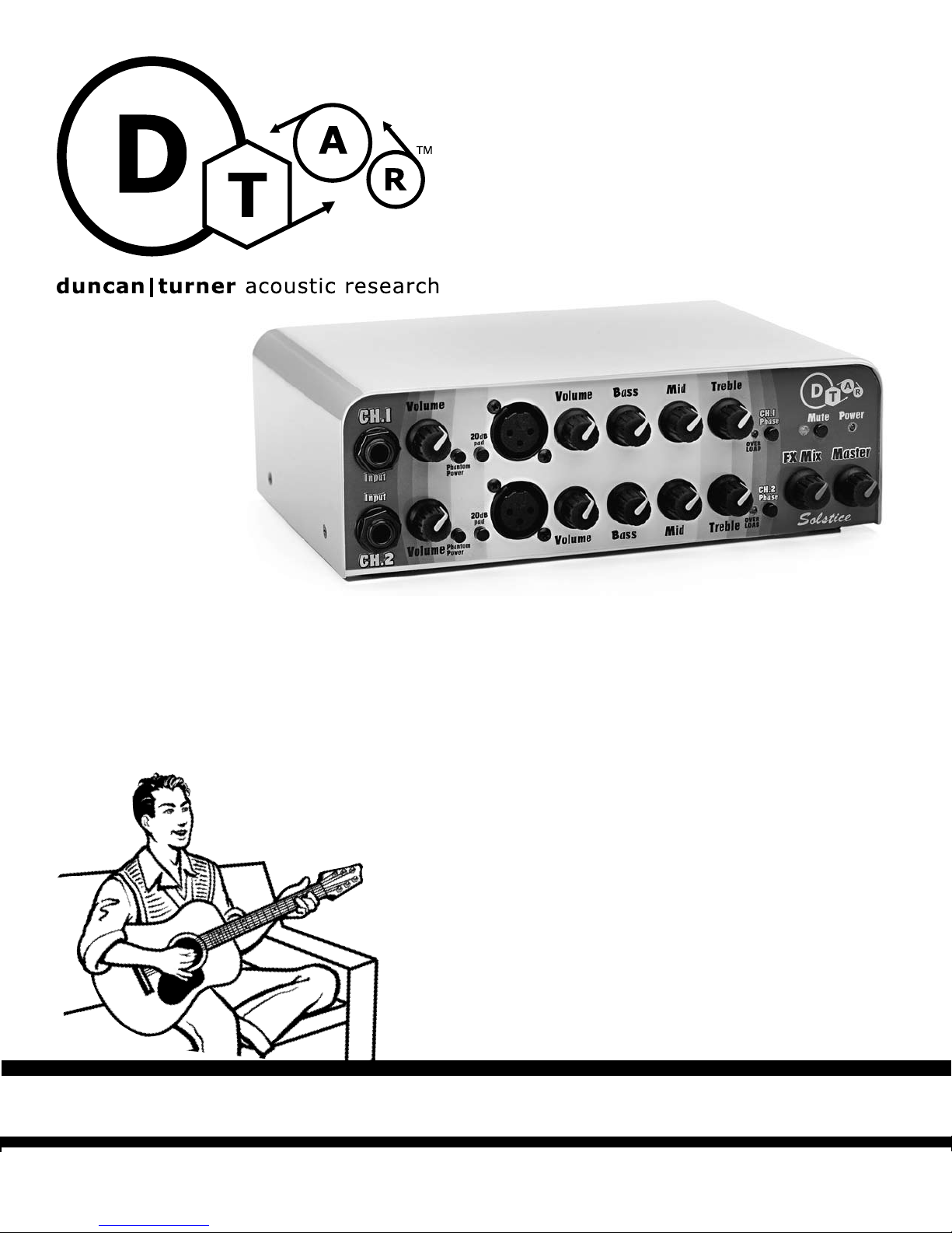
SOLSTICE
High Quality, 2-channel Mixer|Blender Preamp
Did you ever wonder how the best acoustic musicians get that great
sound night after night in every venue? One of the secrets they’ve
learned is that their signature sound not only includes their instruments,
but also their pickups, microphones, cables, and the all-important preamplification and equalization stages of the signal chain. Duncan-Turner
Acoustic Research (“D-TAR”) is dedicated to providing the electronic links
between your strings and your listeners’ ears so you can get a consistently great sound under virtually any circumstance, day in, day out.
D-TAR is a company founded by musicians who want
to make the kind of gear our fellow musicians deserve.
We’ve spent a lot of time listening to and playing fine
instruments as well as amplification and recording
gear, and we are dedicated to building the best sounding gear with the most useful features that we can. We
would like to hear your comments on how you use your
Solstice Mixer/Blender Preamp, and hope the music you
make with it fulfills your dreams.
“WITH RESPECT TO ACOUSTIC TONE”
|
DUNCAN
TURNER ACOUSTI
C RESEARCH 5427 hollister ave santa barbara ca 93111.2345 tel 805.964.9610 fax 805.964.9749 www.dtar.com
Page 2

SOLSTICE
TM
Basic Setup
Inputs
The regular 1/4” input jacks for each channel are very
high impedance inputs; this means you can plug in any
kind of pickup, active or passive, and get the fullest frequency response possible. These inputs also accommodate “stereo” signal sources coming in on a “TRS” (tip,
ring, and sleeve) plug; this is a common configuration
when using dual source pickup systems. With Solstice,
you can plug a stereo input plug into either channel.
Many modern acoustic pickup systems (such as the
D-TAR Timber-line cable pickup) are coupled with
onboard buffer preamps. The high impedance inputs
of Solstice work perfectly fine with these as well,
providing no “load” to the signal and thus preserving
the signal just as your cable delivers it.
Getting Top Performance
Right Away
One of the first things you should know about Solstice
is setting the “Gain” and “Output” volume controls for
best performance and lowest noise. Most of the controls, inputs, and outputs are pretty much self evident,
but to get maximum headroom and lowest noise, you
should adjust the gain control(s) so the clipping light
comes on just a bit when you play or sing your loudest
into the unit. Then control the volume at the output.
With the LED is just flashing, you have about 6 dB more
headroom before Solstice goes into clipping. This is
covered later in the manual, but it is the key to getting
superior performance from the unit, hence we mention
it here.
Cable Connections, Front Panel – Inputs
1. Jacks 1 and 15 are stereo 1/4” inputs. These inputs
are ultra-high impedance on the tip connection and will
accept un-buffered piezo signals (e.g. under-saddle pickups) as well as active and passive magnetic pickups. The
ring connection can be supplied with phantom power
for microphones or for active pickup systems that work
from off-board power. The ring signal is automatically
assigned to the channel opposite of the one plugged
into, assuming that the other channel’s 1/4” input jack is
unused. To take advantage of the stereo input feature, a
stereo cable must be used, with the pickup signal on the
tip and the microphone signal on the ring.
2. XLR jacks 5 and 19 are intended for microphone level
signals. 40dB of gain is provided with the option of a
20dB pad (4, 18) that can be used with high output condenser microphones.
Cable Connections, Rear Panel – Outputs
1. 1/4” jack 4 is intended as the cable connection to a
power amplifier. Its level is controlled by the Master volume on the front panel. It can be shut off with the Mute
switch.
2. 1/4” jack 5 is intended as a tuner output, but can be
used as an auxiliary output for many purposes. It is not
affected by the Master volume or the Mute switch.
3. XLR jack 3 is a line level balanced output. It contains
the blended signal from both channels.
4. 1/4” jacks 7 and 8 are the send and return jacks for
the master effects loop. The signal output is line level
(+4dBu or 1.2V RMS) and intended for professional
effects processors.
5. 1/4” stereo jacks 10 and 12 are insertion points for
channels 1 and 2, respectively. They can be used as individual channel effects loops or as points where a signal
can be taken out of or inserted into the individual channels’ signal chain. A stereo cable is required for most
functions involving the insertion jacks; the send signal is
on the tip and the return is on the ring. The input impedance is low (4.7K ohms), so it will be necessary to drive
the return side with an active device.
6. XLR jacks 9 and 11 are balanced signal outputs for
each channel. They can be used as individual balanced
signal sends to a mixing board or for recording a live
performance. This feature will also allow the Acoustic
Mixer to be used as a stereo mic preamp.
Setting the input level properly for lowest
noise operation
1. Turn the Master all the way down.
2. Plug the instrument or microphone into the appropri
ate input jack on the front panel.
3. Turn up the input Volume control for the jack that
you have plugged into until the red overload LED just
begins to light when you are playing or singing loudest.
4. Turn up the Master until you approach the desired
sound pressure level. If there is any tendency towards
acoustic feedback, try using the Phase Reverse button.
5. Adjust the EQ, if necessary. If a significant amount of
EQ is used, it may be necessary to re-adjust the input
and output levels slightly.
-
1
Page 3
SOLSTICE
TM
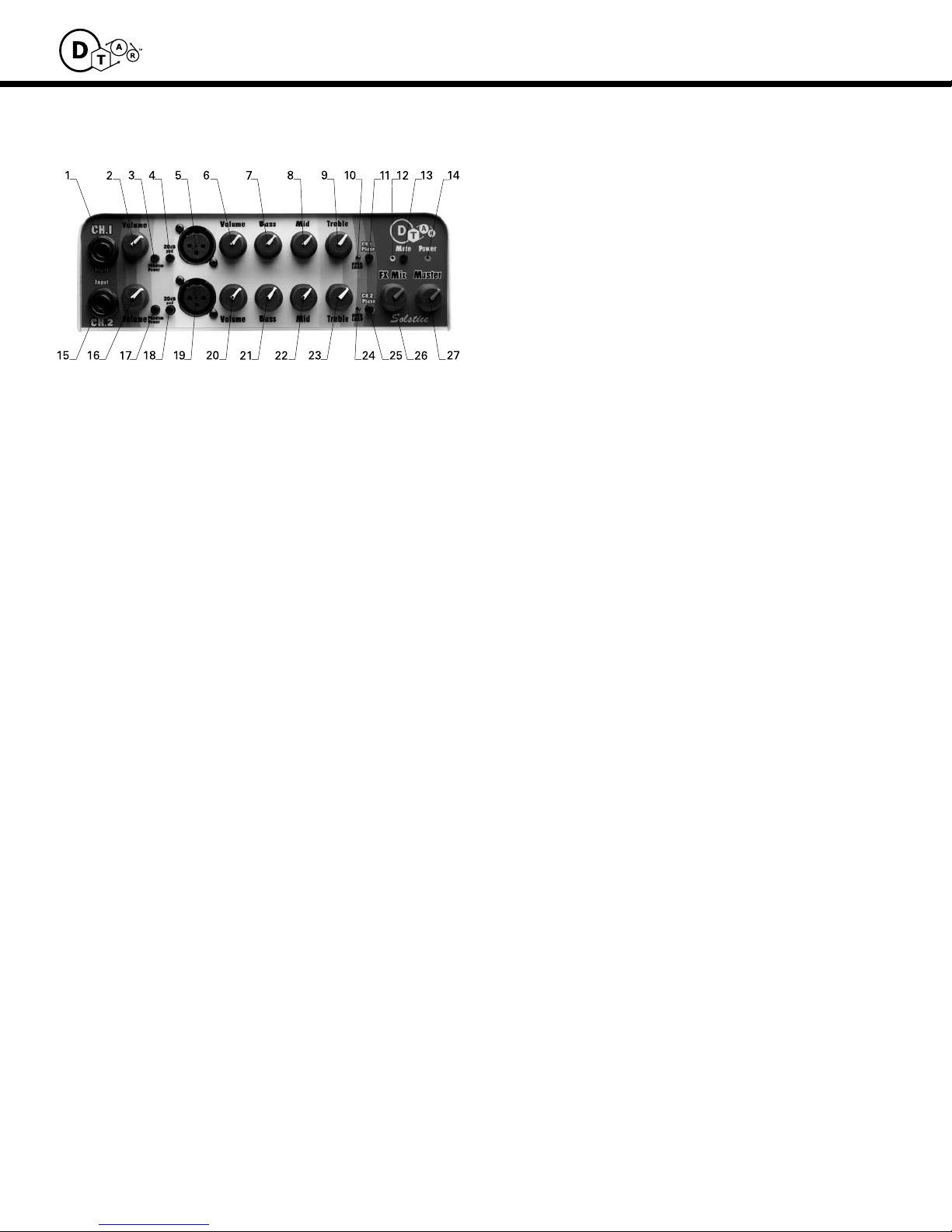
Explanation of features
Front Panel
1, 15 - High Impedance Input Jacks
These inputs can be used for basically anything connected to
a 1/4” plug. The input impedance is 10Meg Ohms (10,000,000
Ohms), so they are well suited to piezo type pickups (for more
information on Impedance considerations, see Appendix A.)
The input stage is a low-noise hybrid circuit with internally
adjustable gain variable from 0dB to 24dB. We have pre-set it
at 18db. This allows a signal of nearly 1 Vrms to be present at
the input without clipping.
Both Ch.1 and Ch.2 input jack will accept stereo signals, but
this feature is functional only if one of the two high impedance inputs is unused. In other words, you can plug a stereo
signal into channel 1, and the signal present on the ring will
be automatically routed to the unoccupied channel 2, or vice
versa. If the phantom power switch is engaged, +15V will be
supplied to the ring of the respective channel jack.
Please note: Because of this unique feature, a pop noise will
tend to be generated when removing a plug from either jack.
Therefore, it is advisable to either turn the channel volumes
down or engage the Mute button before removing a plug
from the high impedance input jacks.
2, 16 High Impedance Input Volume Control
Acts as a normal volume control located directly after the gain
stage of each respective high impedance input. Turn the input
gain controls up until you just see the red LEDs flash on the
highest peak notes and you can leave it there – you still have
6dB of headroom before hard clipping.
3, 17 Phantom Power Button
Engages or disengages +15V phantom power for each channel. Press button in to engage. Phantom power will be present
at the + and – terminals of the XLR input and at the Ring connection of the High Impedance input. Please be sure to only
engage phantom power if it is truly needed in your system.
Inappropriate use of phantom power could be harmful to certain electronic devices in your signal chain.
4, 18 20dB Mic Pad
Push this button in to engage a 20dB pad (gain reduction) on
the XLR input if your microphone signal is particularly hot.
5, 19 Microphone Inputs
This stage is another low-noise hybrid circuit. The design
is unique, but is very similar to some stages used in top of
the line mixing consoles. The gain is set at 40dB but can be
reduced to a level more compatible with high output condenser microphones by engaging the 20dB pad switch.
6, 20 Microphone Volume Control
Acts as a normal volume control located directly after each
respective mic amp.
EQ Controls in General
The Solstice EQ section is made up of filters composed of low
noise discrete components that are side-chained out of the
direct signal path. For more information on the subject of
EQ, see Appendix B.
7, 21 Bass Control
The Bass control provides 12dB of boost and cut and is centered at 155Hz/Q-.61.
8, 22 Midrange Control
The Midrange control provides 12dB of boost and cut and is
centered at 796Hz/Q-.56.
9, 23 Treble Control
The Treble control provides 12dB of boost and cut and is centered at 10KHz/Q-.37.
10, 24 Clipping Indicators
Indicate that the signal level, as sensed after the EQ section, is
6dB below clipping or +14dBm. At the onset of clipping you
will start to hear audible distortion, a sign to turn down either
your input gain control or to back off of EQ boost. If you are
seeing the indicator light up using a microphone plugged into
one of the XLR connectors, you might try engaging the 20 dB
mic pad. See “Setting Your Level” on page 1.
11, 25 Phase Switch
Allows reversal of signal phase for feedback control or to
provide phase agreement between two signal sources.
See Appendix C for more information on phase.
12 Mute Indicator
The yellow LED will be lit when the Mute button is engaged.
13 Mute Button
Removes the signal normally present at both the XLR output
and the single ended output. The Tuner output remains functional to allow for silent tuning. The mute LED will be lit when
the mute is engaged. For more information on the use of the
mute and using a remote foot switch for muting, see the section on page 3.
14 Power Indicator
Shows the presence of DC power from the power supply.
The power remains on until the cable from the wall-mounted
transformer is removed or until the transformer is unplugged
from the wall. Note that there is no power switch on Solstice;
if it’s plugged in it’s on!
26 Effects Mix
Blends the signal present in the Master Effects Loop with the
dry signal. If no external device is plugged into the Master
Effects Loop jacks, this control will have no effect on the signal.
27 Master Volume
Master volume controls all blended signal output for both the
XLR, and 1/4” outputs
2
Page 4

SOLSTICE
TM
Explanation of features
Rear Panel
1 AC Power Input Jacks
Plug the 15VAC power wall mounted transformer supplied with
the product into this jack.
2 Ground Lift Switch
When this button is pushed in, the ground for the Master XLR
Output is lifted. This switch can be useful for breaking ground
loops that can occur during recording sessions. The XLR
ground should typically remain engaged.
3 Balanced Output, Blended Signal
This jack provides a balanced, low impedance signal that is
independent of the Master Volume control. It is located near
the end of the signal chain, just before the Master Volume and
is a blended signal of both channels. This output will typically
be used to feed the Solstice’s blended output to a PA or recording system.
9, 11 Channel XLR Balanced Output
This jack provides a balanced, low impedance signal that is
taken post-EQ at the end of each channel’s signal chain but
before any mixing has occurred. It allows the unit to be used
as a stereo mic preamp for recording purposes or provides
individual channel signals to go to a mixing board.
10, 12 Channel Insertion Point / Effect Loop
Stereo jacks are provided for each channel to allow flexibility
in the use of effects and in sending and receiving auxiliary
signals. The Send signal is assigned to the Tip and the Return
signal is assigned to the Ring. The tip signal can also be treated
as auxiliary signal outputs and, likewise the ring signal can be
treated as auxiliary signal inputs. These effect loops are seriestype, so inserting or removing a signal will break the internal
signal path. It will be necessary to use a stereo cord and a Y
connector to insert an effects processor (Radio Shack 6 foot Yadapter 1/4” stereo to (2) RCA plug cable #42-2547 and 2 each
of RCA plug to 1/4” mono phone plug adapter #274-320). If it is
desired to take an auxiliary signal out, you can simply insert a
standard patch cord. If it is desired to insert an auxiliary signal,
such as a drum machine, it will be necessary to make a cable
with a stereo plug on one end and mono on the other. The
cable must be wired with the tip on the mono end connected
to the ring on the stereo end. The mono end is then connected
to the signal source and the stereo end is plugged into the
Acoustic Mixer channel Insertion jack. As an option, you can
use a Hosa stereo “Y” cord (part #STP-201, 202, 203, or 204)
and just use the mono plug of the “Y” which is connected to
the ring of the stereo plug.
4 Single Ended Output
This jack is located at the end of the signal chain and is
controlled by the Master Volume. It is buffered and provides
very low output impedance. This output will typically be used
to send Solstice’s signal to a power amplifier.
5 Tuner out
This jack provides an auxiliary signal that is located pre-Master
Effects and is unaffected by the Master Volume or the Mute
switch. It is ideal for connection to a tuner, but can be used to
provide an extra output signal for whatever use that comes up.
6 Mute Footswitch Jack
This jack allows remote access to the Mute function. If you
plan to employ remote foot switching, a special stereo footswitch is needed in order to have the Mute light turn on and off
properly. A simple schematic is available if you wish to make
your own footswitch.
7, 8 Master Effect Loop
These jacks provide send and return locations for an effects
processor. The level is optimized for +4dBu effect processors.
When using –10dBu processors, it may be necessary to reduce
input levels somewhat to avoid overdriving them.
Troubleshooting Guide:
Common Problem Try the Following Steps
No sound • Make sure power indicator is on
• Check mute switch / foot switch
• Make sure your red over-load LED indicator is
flashing to show a signal
• Unplug the output to make sure the problem isn’t
further downstream (in the power amp)
Distorted sound • Check input level and make sure it’s not overloaded
• Lower effect input level (it may be necessary to raise
the output level of the effect to minimize signal loss)
Excessive noise • Input level is set too low
• Output level is set too high
Excessive hum • Try unplugging instrument to isolate the source
• Check shielding on input devices
• Try ground lift on master balanced (XLR) output
• Not enough gain on the mic channel Make sure
20dB pad is not engaged
• Excessive amount of EQ boosting
(Note: un-buffered high-impedance signals are very suscep
tible to hum) (See excessive noise above)
3
Page 5

SOLSTICE
Hi-Z Input
Single ended
10M - 0 to 24dB
Gain trim
Balanced Input
1k - 40dB
20dB Pad
Summing Amp
12dB fixed gain
EQ Summing
non-inverting
B/M/T Gyrators
Phase
Inverter
Summing Amp
12dB fixed gain
EQ Summing
non-inverting
B/M/T Gyrators
Phase
Inverter
Level
Indicator
Level
Indicator
Summing Amp
6dB
Return
Amp
Buffer Amp
Master FX Loop
FX Blend
Control
Tuner Out
Output Buffer
non-inverting
Blended Output
Balanced Line
Mute
Switch
Master
Volume
Hi-Z Input
Single ended
10M - 0 to 24dB
Gain trim
Balanced Input
1k - 40dB
20dB Pad
Ground
Lift
Channel 1 Balanced Out
Channel 2 Balanced Out
Functional Block Diagram - DTAR Acoustic Mixer
Blended Signal
Output
Back Panel
front
panel
front
panel
front
panel
Channel 1
Insertion
Channel 2
Insertion
Tip - Send
Ring - Return
TM
APPENDIXES to SOLSTICE INSTRUCTIONS
A) IMPEDANCE CONSIDERATIONS WITH ACOUSTIC INSTRUMENT PICKUPS
Piezo pickups are particularly sensitive to the “input impedance” of the
first stage of electronics into which they are plugged. The effect is the
audio equivalent to trying to balance a 200-pound gorilla on a seesaw with
a 40-pound child...without moving the fulcrum point. If the input imped
ance is too low, as it is with most guitar amps or PA boards, the resulting
mismatch will rob your pickup of output and low end warmth, just about the
last things you want when amplifying an acoustic instrument! Impedance
matching is basically a balancing act with a slight twist: it is best to send a
lower impedance output (for instance a pickup) to a preamp with an input
impedance many times greater.
Also, pickups do not do a great job of driving a signal down a cable, and
this is why most high quality piezo pickups have on-board preamps to condition the signal for its trip to the amp or console. If you do use a “passive”
piezo system in your instrument, keep cable length to a minimum. You will
know whether your guitar pickup system is active or passive by whether it
needs battery power or not. Some magnetic pickups and nearly all piezo
pickups work best when there is a preamp/buffer stage right in the guitar.
Pickups do not make great “line drivers” and you can suffer significant signal loss and degradation with long runs of cable. We have designed your
Solstice preamp to work with either style of pickups, but if you are going
to go passive, use the shortest, lowest capacitance cable you can get to
preserve maximum signal.
B) EQ, USE AND MISUSE
One of the keys to getting great sound is to use just as much EQ as you
need and no more than necessary. A good rule of thumb is that if a signal
source needs a lot of EQ to sound decent, it’s probably a bad source. In the
best recording studios in the world, the engineers will first choose the best
microphone(s) for the instrument and work carefully with mic placement to
get the sound they are after. Only then will they apply EQ to shade the basic
sound they are getting from the straight sound of the mic. Overzealous
use of EQ can cause more problems than it solves by altering the phase
relationships among sounds and by just adding too much noise and a processed quality to the end result. If you think your pickup needs a lot of EQ
to sound right, perhaps what you really need is a better or more appropriate pickup.
It is helpful to understand just what problems you are trying to solve using
EQ. Is it the guitar sound itself? Is it the sound of the PA? Is it a room
specific problem? It is also important not to be duplicating or counteracting
what might be going on elsewhere in your system with other EQ devices.
You may not even realize how much EQ your instrument signal is going
through when you plug into a PA, there may be some in your instrument,
-
there’s the EQ on Solstice or an amplifier, then the EQ on the channel(s) of
the mains PA console and perhaps a separate monitors console, there may
be auxiliary outboard EQ patched into the console, and then there is usually
some EQ dedicated to the speakers and/or room taming. You may just be
dealing with as many as five or six different equalizers in your signal chain
when one or two may just do the trick.
One of the best ways to dial in your sound for amplified acoustic instru
ments is to work with headphones to dial in your pickup blend (if using dual
sources), EQ, and effects. Take Solstice’s output into a headphone amp or
through a console and use high quality headphones to monitor your sound.
This way you will know that you are using your gear to get just the right
instrument sound free of anomalies with loudspeaker response or room
resonances. Then when you play out live, you can deliver your concept of
correct tone to a sound engineer with the instructions to do nothing or as
little as possible to that sound. He or she should already have their dedicat
ed PA and room EQ set correctly, and then the only further possible need of
EQ might be for feedback control in cases where you are trying to achieve
loud monitor levels on stage with acoustically lively instruments.
Some musicians go so far as to carry their own vocal mics with them along
with acoustic instrument preamplification and even stage monitors so
they have as close to the same sound on stage every night no matter what
might be happening in the house with the main PA. Solstice and D-TAR’s
other fine acoustic amplification gear makes this easy. You can carry your
own personal sound with you, feed that to the PA, and have several less
things to worry about.
C) A FEW NOTES RE. PHASE, SOUND, AND FEEDBACK REDUCTION
Acoustically, a sound wave is physically made up of alternating low and
high pressures acting on your eardrums. Phase is the relationship, in time,
between the “the peaks and valleys” of two sound sources (or signals).
If the soundboard or loudspeaker creating a guitar signal first moves out
ward, the first thing that hits your ear is a positive pressure, which pushes
your eardrum inward. If the soundboard or speaker cone first moves in, it
creates a negative pressure on your ear, pulling the eardrum out.
Guitar tops, pickups, preamps, amplifiers, and speakers all affect this phase
relationship, and things really get complicated when you combine these
elements and then start pushing sound levels up further and further. Certain
phase relationships among all these elements can lead to uncontrollable
feedback at even moderate volume levels.
Having the ability to switch the phase relationship between your guitar
signal and the speakers can make all the difference between being in feedback hell or sonic heaven. This can be worth 4 to 10 dB more level when
you need it.
-
4
Page 6

SOLSTICE
TM
Blending two signal sources from an acoustic instrument makes things
even more complicated. The most common combo would be UST (Under
Saddle Transducer) plus internal mic or UST plus magnetic pickup. Often
one phase relationship between the two sources will sound thin and lifeless while switching the phase of one of the two signals can fatten up the
sound and bring the instrument to life. With Solstice you can switch the
phase relationships between the two channels, and also switch the overall
phase of the output by switching both channels if necessary.
The caveat when using phase switching to control feedback is that if you
change your position on stage relative to the speakers, you may find that the
feedback threshold changes, and that you are better off switching phase the
other way. Your relationship to the phase of amplified sound is also affected
by your distance from the loudspeaker(s) and the frequency of the problem
notes. This is one of those “try it to get it right” situations.
D) GLOSSARY OF SOME AMPLIFICATION TERMS
AMPLIFIER
A device for making small electrical signals bigger. The amplifier was actu
ally invented in the late 1800’s before there were any devices that could
make building one possible! In music, the term often refers to a self con
tained “combo amp”—-an electromechanical device combining a preamp,
amplifier, and loudspeaker usually including some kinds of tone shaping
circuitry. With Solstice, you have the option of “custom building” your
amplifier by matching the preamp/mixer/blender stage to a separate power
amp and loudspeaker system.
BUFFER
A preamplifier designed to isolate the source from the next stage of ampli
fication. Buffer amps have high input impedances and low output impedances and can also feature some “gain” or signal boosting capability.
Buffers are required with piezo crystal or piezo polymer pickups, and are
often built into acoustic-electric guitars. Solstice features high impedance
buffer stages for both channels so you can use either active or passive
pickup systems. D-TAR makes several on-board buffered pickup systems
for acoustic instruments.
CARDIOID MIC
A microphone designed to be more sensitive in one direction than in oth
ers, a directional mic. Cardioid mics are used more often than other types
on stage because they make it easier to isolate one voice or instrument
from the others for mixing. Hypercardioid mics, sometimes called shotgun
mics, are designed for use at a distance as they can be aimed at the sound
source and used from many feet away. The good old Shure SM-57 and 58
are cardioid mics.
CHORUS
An electronic device that can split a signal, mildly shifting the pitch and
timing of one part, then mix it back in with the original signal. The effect is
roughly like several people (they’re the chorus) playing the same part at the
same time. Solstice has effects loops to allow convenient interface with
chorus effects.
COMPRESSOR
A processor that “squeezes” the dynamic range of the signal by limiting
peaks and bringing up the level of soft passages. A limiter can be used to
fatten a sound or give it more apparent sustain. If you’ve ever wondered
why music sounds kind of flat on FM radio compared to live, overuse of
compression can be one reason. On the other hand, the Beatles used tons
of compression on their acoustic guitar recordings and it sounds great.
Can be used in Solstice effects loops.
CONDENSER MIC
A microphone in which an electrically charged diaphragm moves with
sound waves while a charged back plate stays stationary. Because the
diaphragms of condenser mics can be made very light in weight, the frequency response can be very good with a condenser mic. Neumann mics,
considered by many to be the ultimate mics for recording voice and acoustic instruments are condenser mics. “Condenser” is an old term for capaci
-
-
-
tor. Condenser mic derive their name from the fact that they are sensing
the change in capacitance between the diaphragm and the
backplate and converting it to a signal voltage.
CONTACT PICKUP
Sometimes called “soundboard transducers” are most often piezoelectric
accelerometers (acceleration monitors). They put out an electrical signal
that is an electrical equivalent to the mechanical vibrations occurring
where they are placed. The D-TAR SA-2 is an excellent example of this
type of pickup.
DI (see also “DIRECT BOX”)
The British term now common in the US for “directly interfacing” a pickup
signal into a recording or PA console, thus bypassing amplifiers, speak
ers, and mics. Used especially for electric bass to get a clear tone. Many
home enthusiasts directly connect their acoustic guitars to the recording
device to gain better isolation from track to track than they can get just
using microphones. Solstice has XLR outputs to allow using it as a DI
source.
DIAPHRAGM
In a microphone, a thin, stretched, plastic film, the equivalent of your ear
drum. The diaphragm vibrates with sound, then transforms that acoustical
energy into an electrical signal that can be amplified.
DIGITAL DELAY (DDL)
A signal processor that converts analog signals into a stream of digital
information that can be delayed and mixed to give echo-like sounds. Digital
delay is usually included with other sonic colorings in multi-effects processors. Can be used with Solstice’s effects loops.
DIRECT BOX
A device used to buffer or isolate guitar and bass signals so they can be
“DI’d”. Many of the direct boxes designed for electric guitars and basses
do not have a sufficiently high input impedance for interface with piezo
pickups. Direct boxes can either be passive, using transformers, or active,
using tube or transistor based circuitry. Solstice serves as a high quality
direct box.
DYNAMIC MIC
A microphone which works like a backwards loudspeaker. The diaphragm
is attached to a small coil of very fine wire that is surrounded by a magnetic field. When the diaphragm and coil vibrate with sound waves, a small
electrical signal is generated in the coil that can be amplified through a
mic preamp and other devices. The Shure SM-57 & 58, two of the most
common mics used in clubs and studios, are dynamic mics. Dynamic mics
are noted for being tough; the mic you can drive a nail with is probably a
dynamic.
EFFECTS LOOP
A set of jacks on an amp or preamp which allow sending a signal out to an
effect and bringing the modified sound back to the main unit. The advantage of an effects loop is that it is buffered (yes, same concept) on the
output and input, the effect will “see” a predictable impedance and level,
and the modified signal can be master volume controlled in the main amp
or preamp.
ELECTRET MICROPHONE
Miniature mics that work on condenser mic principles but have permanently charged polymer diaphragms. Electret mics have miniature preamplifiers
built in and require low voltage DC power (usually 1.5 to 18 volts) often sup
plied as “phantom power.” The Seymour Duncan Mag Mic uses an electret
element for it’s second source with “on-board” blending.
EQUALIZATION or EQ
An electronic means of shaping frequency response; the term generally
refers to sophisticated tone control circuitry. Originally used to mean cor
rection for the unequal frequency response of old PA, recording and play
back gear.
-
-
-
-
-
-
5
Page 7

SOLSTICE
TM
EXTERNAL MIC
Generally referring to the good old practice of standing in front of a mic
on stage as opposed to installing a mic in your guitar. You’ve seen them,
you’ve used them, and now you know what they’re called. There are now
some bracket devices for mounting an external mic on your guitar.
FEEDBACK
Yowl, howl, etc., feedback by any name is the sonic nemesis of the performer. It happens when amplification goes beyond control, and the ampli
fied sound itself is re-circulating and becoming further amplified. The sonic
equivalent of Chernobyl—-audio meltdown. “Ringing” is the precursor of
feedback and refers to a barely controlled resonance just shy of feedback.
D-TAR’s “Equinox” features two notch filters designed to combat feedback.
FLOATING PICKUP
A magnetic pickup mounted to the end of the fingerboard on a guitar or
to some other non-vibrating part of a musical instrument. Floating pickups
are sometimes used on archtop acoustics so the adding of a pickup will
not interfere or change the vibration pattern of the top. Seymour Duncan
makes a variety of floating pickups including the Bob Benedetto signature
pickup for use with archtop guitars.
GRAPHIC EQUALIZER
An equalizer that uses sliding potentiometers (slide pots) to control the
level of the signal in various frequency bands. Called so because the knobs
form a graphic representation of the frequency contouring. Graphic equalizers are generally either “1/3rd octave” or “1/10th octave” referring to the
width of the audio bands covered.
HUMBUCKING PICKUP
A type of pickup using two coils to cancel magnetically induced hum.
Invented by Seth Lover at Gibson in the 1950’s, the “humbucker” is noted
for it’s loud and warm sound. Check the Seymour Duncan website for the
world’s most complete selection of humbucking pickups.
IMPEDANCE
A measurement of the resistance to the flow of AC (which is what audio
signals are); impedance is affected by resistance, capacitance, and inductance in a circuit and is also frequency dependent. Impedance is often
mistaken for resistance and is also incorrectly thought of as being a measurement of the voltage from a pickup. In practical terms, you want low
impedance sources feeding into high impedance loads; this gives maximum
accuracy in signal transfer.
INTERNAL MIC
A microphone, generally an electret condenser mic, mounted inside an
instrument.
LIMITER
A limiter keeps hot signals from overloading the next stage of electronics.
Les Paul takes credit for inventing the limiters as used in recording studios.
He related that he got the idea from watching Mary Ford turn her head
while singing loud passages as she watched the recording VU meters. She
physically limited the input signal to the mic with this technique.
LINE-LEVEL
The voltage level at which most pro gear sends pre-amplified signals to
other devices such as equalizers, limiters, compressors and power amplifiers. Generally considered to be +4(dBm) or 1.2 Volts RMS.
MAGNETIC PICKUP
A pickup that consists of a magnetic structure and one or more coils of
very fine wire which “transduce” or transform the vibration of plain steel or
steel cored wound strings into an electrical signal.
MIDI
Musical Instrument Digital Interface, the computer language used in
modern synthesizers and signal processors to “communicate” with other
devices.
MINI-MIC
Miniature mics derived from hearing aid and CIA “mic in the martini olive”
technology. These are generally electret mics, a simpler variation on the
condenser mic.
MIXER
Used to combine or mix multiple sound signals into a mono, stereo, or other
simpler signal to go onto tape, a CD, or through a PA system. Also refers
-
to the person who does the mixing, not to be confused with re-mixer, the
person who doesn’t mix live, but works on mix-downs of pre-recorded mixups. If you’re reading this, you probably have a Solstice mixer/blender.
MONITOR
Generally referring to a set of speakers aimed at musicians used to give
performers a chance at hearing themselves on stage. Watch for “In-Ear”
monitors the latest thing in stage monitoring; these are like hearing aids
for musicians. The term “Monitor” implies accuracy as well as in, “Studio
monitor speaker.”
“NATURAL” SOUND
Often achieved with the most unnatural of means, natural sound is the Holy
Grail of most acoustic musicians. To hear it, try listening to truly acoustic
music - no, no, not MTV Unplugged! Our goal at D-TAR is to help you
achieve the most natural sound you can get … plugged in.
NOTCH FILTER
A specialized kind of equalizer that can be tuned to “notch out” problem
frequencies without affecting neighboring frequency bands. Usually used
to kill feedback frequencies. D-TAR’s “Equinox” equalizer features two
switchable notch filters.
OMNIDIRECTONAL MICROPHONE
A mic that picks up sound more or less equally in a spherical pattern all
around the mic’s diaphragm.
ONBOARD and OUTBOARD
Generally refers to where pickup buffering and/or EQ stages are located.
Onboard in your instrument, outboard is somewhere else, man.
PA SYSTEM
Originally “Public Address” system. Do you remember, “Would Johnny
Brown please come immediately to the principal’s office?” Some of the first
PA systems were used in department stores and schools. Now the term
refers to sound systems designed for amplifying live music.
PARAMETRIC EQ
A type of equalizer that allows continuous control over three parameters:
frequency, bandwidth, and amount of boost or cut. While a bit harder to
intuitively understand than graphic equalizers, parametric EQ is preferred
by pro audio engineers for fixing specific sonic problems without affecting
other frequencies as happens often with graphic EQ. D-TAR’s “Equinox” is
a three band parametric EQ with two bands of notch filtration.
PHANTOM POWER
A system wherein DC current is run up the same cable used to send the
signal down to a mixer. Used most often in the studio to power high end
condenser mics, but sometimes used for powering mics and other electronics inside guitars.
PHASING
The relative polarity of two or more signals that contain similar information.
In-phase signals add together while out-of-phase signals tend to cancel.
See Appendix “C”.
PICKUP
Any device that changes vibrations of a soundboard or strings into an elec
trical signal. The most common pickups are magnetic and piezoelectric.
-
6
Page 8

SOLSTICE
TM
PIEZO PICKUPS & PIEZOELECTRICITY
Certain crystals, ceramics, and polymers exhibit the phenomenon of piezo
electricity. Piezo means pressure in Greek, and piezo materials directly
transform mechanical vibrations into electrical signals. Most under-saddle
pickups, like D-TAR’s Timber-line and SA-2 pickups are based on the piezo
electric effect.
POLEPIECES
These are magnetically conductive elements of a magnetic pickup used to
shape the magnetic field. Some pickups such as the classic humbuckers
have adjustable polepieces for making fine adjustments to the volume of
each string.
PREAMP
An electronic device usually designed for matching low-level signals to
a power amplifier. EQ and other signal processing is usually done with or
within the preamp stage. Solstice is a preamp in addition to being a mixerblender.
PRESENCE CONTROL
A section or knob of an equalizer operating in the upper midrange.
PROCESSOR
Any signal-modifying device often combining several effects such as
EQ, chorus, delay, and reverb. You can use processors with Solstice by
inserting them in the effects loop(s). Digital multi-effects units are com
monly used for modifying guitar tones.
PROXIMITY EFFECT
A characteristic of cardioid mics whereby low end is boosted as you get
closer to the mic. Proximity effect can make a mic sound overly boomy if
you get too close.
RACK MOUNT
Gear that is designed to be mounted in the international standard 19”
“relay rack”. The standard was set by the phone company for its racks
upon racks of electrical switches that routed phone calls in days of old
when phones had dials and dial tone really meant something.
REVERB
The sound of surf music, echoey without the discreet pulses or repeats
obtained from delay units. The original reverb effect was (and still is)
derived from vibrating a set of springs with a little loudspeaker-like driver
and picking up the reverberant sound at the other end of the springs.
RIBBON MIC
A type of microphone in which a very thin conductive ribbon, usually alu
minum, vibrates in a magnetic field. A small current is induced in the ribbon
itself and is then preamped like other types of mic signal.
SIGNAL
The word I’ve used more often than any other in this glossary. In amplifi
cation, the signal is the electrical analog of the musical note(s) traveling
through the amplification chain.
SINGLE-COIL PICKUP
Refers to the simplest style of magnetic pickup having one coil of magnet
wire. Noted for a certain clarity and focus. Seymour Duncan is famous for
it’s recreations of the most famous single coil pickups from the “golden
era” of magnetic pickup design.
THREE-BAND EQ
Sounds like a good night at the Fillmore, but in our context it refers to types
of equalizers having low, mid, and high frequency controls. Solstice fea
tures a three-band equalizer on each channel.
TRANSDUCER
Any device that changes mechanical or acoustic energy into an electrical
signal or vice versa. Mics, pickups, and loudspeakers are all transducers.
The term transducer is often used with accelerometer style piezo pickups,
but is not exclusive to such pickups.
-
-
-
-
TRANSIENT RESPONSE
-
The quality of how fast a preamp, amplifier, or signal processor responds to
an input signal. Related to “slew rate”. Fast is good, slow is bad.
TUBE
An electrical device that can amplify low-level signals into higher equiva
lents. Tubes are the oldest technology for this purpose and are still preferred by many in preamps, direct boxes, and amplifiers. They’re made of
glass like lightbulbs, and boy, do they get hot!
TWEETER
A loudspeaker designed specifically for high frequencies. Tweeters usually
cover the range from 3000 or 4000 cycles (3 to 4 Kilo Hertz) on up to 20 K Hz.
Think “Tweetie Bird.”
WOOFER
A loudspeaker designed for reproduction of low frequencies, generally
from 20 Hz to 1 to 3 K Hz. “Midrange” drivers are used sometimes to cover
the frequencies between 1 K Hz and 4 K Hz.
Limited Warranty
D-TAR offers the original purchaser a one-year
limited warranty on both labor and materials starting from the day this product is purchased from
an Authorized D-TAR Dealer. D-TAR will repair or
replace this product, at its option, if it fails due to
faulty workmanship or materials during this period.
Defective products should be returned to your USA
dealer, international distributor, or sent direct to our
factory postage prepaid along with dated proof of
purchase (e.g., original store receipt) and a RMA
number clearly written on the outside of the box.
Please call our factory at 805-964-9610 for an RMA
number.
This warranty does not apply to damage to this
product or an instrument caused by misuse, mishandling, accident, abuse, or alteration. Product
appearance and normal wear and tear (worn pain,
scratches, etc.) are not covered by this warranty.
D-TAR reserves the right to be the sole arbiter as to
the misuse or abuse of this product.
D-TAR assumes no liability for any incidental or
consequential damages, which may result from the
failure of this product. Any warranties implied in fact
or by law are limited to the duration of this express
limited warranty.
duncan | turner acoustic research
5427 hollister avenue
santa barbara ca 93111.2345
PN#501055-115 Rev. D
-
7
 Loading...