

Page 1

DStv Switch (5-1)
User Guide
Page 2

Introduction
You’re one step closer to our world of extraordinary entertainment!
This DStv Switch has been specially designed and manufactured for your
DStv Explora and XtraView installations. You’ll need the DStv Switch in
order to connect your DStv Explora to most existing DStv installations.
This User Guide will help you with simple connections to your satellite
dish, your DStv Explora and some XtraView combinations. If you have
another kind of multiswitch or a custom installation, then please refer to
www.dstv.com for further information.
The DStv Switch (5-1) carries a 12-month warranty from the day you
bought it. Terms and Conditions can be found on www.dstv.com.
Some of the information in this guide can get a little technical; as always, we recommend the use of
a DStv Accredited Installer for all your installation needs. It’s easy to locate one in your area - just go
to www.dstv.com.
Page 3
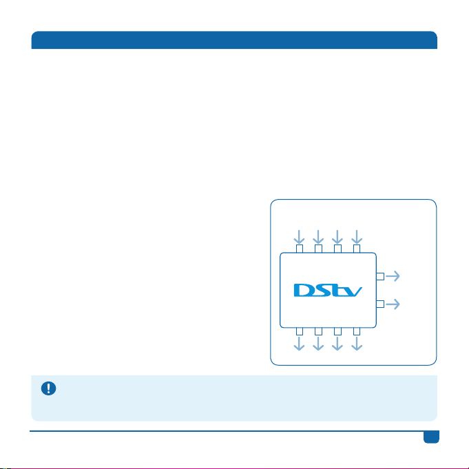
Your DStv Switch (5-1)
• The DStv Switch (5-1) has:
- Four inputs (labelled H/L, V/L, H/H, V/H);
- Four normal multiswitch outputs (labelled 1 to 4); and
- Two Explora outputs (labelled A and B). The DStv Explora can only be
connected to this output.
• Each multiswitch output (labelled 1 to 4) outputs a signal equivalent to a
normal multiswitch output or a single LNB output.
• The DStv Switch comes with 3 cables. You may need additional cabling,
depending on your set up.
• The DStv Switch self-terminates unused
ports, which means you don’t have to cap
them.
• You’ll know your switch is powered when
the blue light is on.
• Keep in mind - this switch is not a signal
booster.
Troubleshooting Tip
If the DStv Switch’s blue light is not on (indicating that it’s getting power), check that the outputs to
the decoder(s) are: 1) Securely connected (both to the switch and decoder), and 2) That the decoder(s)
themselves are switched on and getting power.
DStv Switch (5-1)
Inputs
H/L V/L H/H V/H
1 2 3 4
Multiswitch outputs
A
Explora
outputs
B
DStv Switch - User Guide
1
Page 4
LNB Requirements
• If you are in South Africa or Southern Africa (an IS20* installation), your
DStv Switch (5-1) requires input from a twin, quad or quattro LNB. It will
not work if connected to a single feed or UnicableTM LNB**, even if the feed
is split.
• If you’re in Angola or Mozambique (an E36B* installation), your DStv
Switch (5-1) requires inputs from either a quad or quattro LNB. It will not
work if connected to a twin LNB, single feed or UnicableTM LNB**, even if
the feed is split.
• If you are located anywhere else in Africa (an E36B* installation), your DStv
Switch (5-1) requires input from a twin, quad or quattro LNB. It will not
work if connected to a single feed or UnicableTM LNB**, even if the feed is
split.
If you are unsure of the LNB used in your installation, which satellite your installation connects to, or if
your installation has several multiswitches, we recommend contacting a DStv Accredited Installer. You
can find your nearest one at www.dstv.com
* IS20 is the satellite footprint used for DStv services in Southern Africa. E36B is for East and
West African countries.
** Unicable™, is a standard for single cable distribution of multiple satellite signals. SatCR (Satellite
Cable Router) and CSS (Channel Stacking Switch) both provide Unicable™ solutions.
2
DStv Switch - User Guide
Page 5
Connecting the Inputs from your Satellite Dish
Please Note
• If you have a Unicable™ LNB, you can connect your LNB cable directly to the DStv Explora (there is
no need to use this switch).
• If you have a Unicable™ LNB with multiple decoders in your home, please contact your DStv
Accredited Installer.
• The DStv Switch (5-1) may not be required when connecting the DStv Explora to existing singlecable distribution systems (like those found in apartments or complexes). Please refer to the
installer of the system for confirmation.
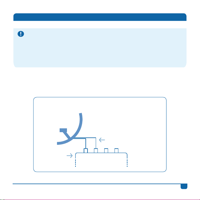
The following diagrams show you how to connect the inputs from your
satellite dish.
Twin LNB Connection (IS20 only)
Twin LNB
Any LNB cable can
connect to any of these
two inputs
DStv Switch (5-1)
DStv Switch - User Guide
H/L V/L H/H V/H
3
Page 6
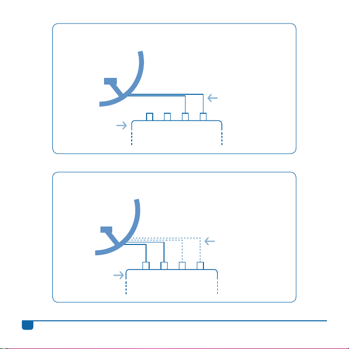
Twin LNB Connection (E36B only)
Twin LNB
Any LNB cable can
connect to any of
these two inputs
DStv Switch (5-1)
H/L V/L H/H V/H
Quad LNB Connection
At least two of the quad LNB cables
have to be connected to the H/L and
V/L inputs. Any LNB cable can go to
Quad LNB
DStv Switch (5-1)
4
the any of the latter inputs.
Optional to
connect the
second two quad
LNB cables.
H/L V/L H/H V/H
DStv Switch - User Guide
Page 7
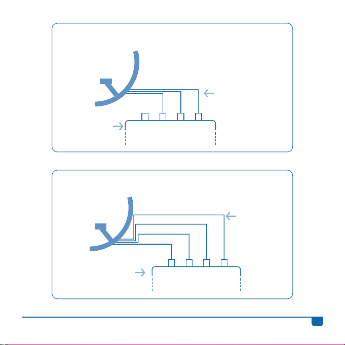
3 Cable Quad LNB Connection
(E36B Angola and Mozambique only)
Quad LNB
Any LNB cable can
connect to any of
these 3 inputs
DStv Switch (5-1)
Quattro LNB Connection
Quattro LNB
DStv Switch (5-1)
DStv Switch - User Guide
H/L V/L H/H V/H
V/H
H/H
V/L
H/L
H/L V/L H/H V/H
Use quattro
LNB output
labels to match
DStv Switch (5-1)
input labels.
5
Page 8
Connecting the Switch to your Decoder(s)
The DStv Switch (5-1) has two Explora outputs (labelled A and B) and four
normal multiswitch outputs (labelled 1 to 4).
• The Explora outputs can only be connected to a DStv Explora, they aren’t
designed to connect to other decoder models. (Note: The DStv Switch (5-1)
can only be connected to one DStv Explora at any one time.)
• The four normal multiswitch outputs can be connected to up to four single
view decoders, one 4 Tuner HD PVR, or a mix of DStv decoders (other
than the DStv Explora). Again, remember that the DStv Explora cannot be
connected to these particular outputs.
These diagrams exclude the connections between decoders that are required for XtraView. For
information on XtraView installations, including connections and settings, please contact a DStv
Accredited Installer or go to www.dstv.com
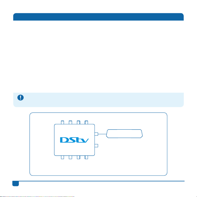
Connecting the DStv Switch (5-1) to one DStv Explora
H/L V/L H/H V/H
A
B
1 2 3 4
Once the switch has been connected to the satellite dish, use the
supplied cable and connect output A or B on the switch to the input
labelled UNICABLE™ IN on the back of your DStv Explora.
DStv Explora
6
DStv Switch - User Guide
Page 9
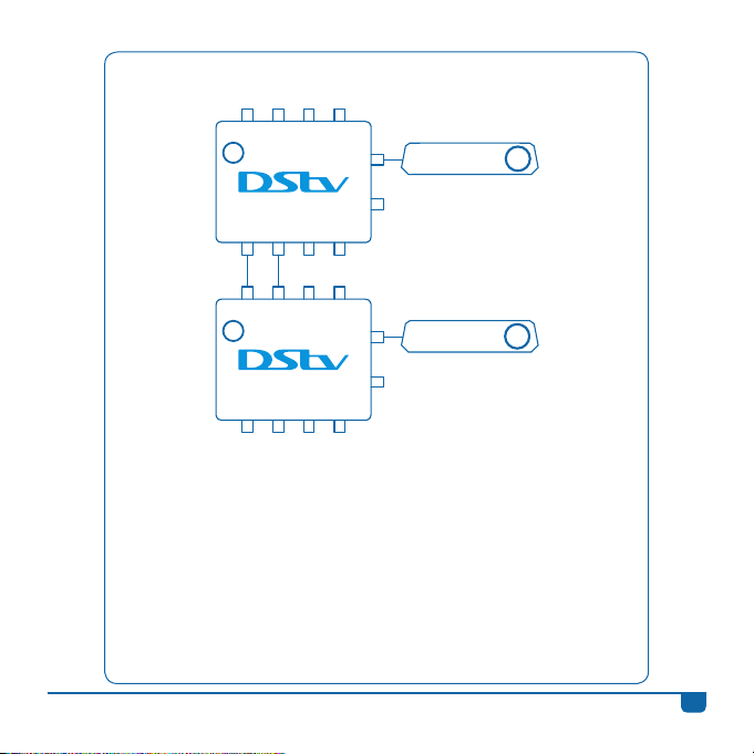
Connecting the DStv Switch (5-1) to two DStv Exploras (IS20)
H/L V/L H/H V/H
1
1 2 3 4
H/L V/L H/H V/H
2
1 2 3 4
This installation requires a DStv Switch per DStv Explora. The DStv Switch
(5-1) can only be connected to one DStv Explora at any one time.
• Once the first switch has been connected to the satellite dish, connect
output A or B on the first switch to the input labelled UNICABLE™ IN on
the back of your first DStv Explora.
• Then, using the provided cables, connect the first DStv Switch to a second
DStv Switch. Connect the outputs labelled 1 and 2 on the first switch, to
the inputs marked H/L and V/L on the second switch.
• Once the DStv Switches have been connected, connect output A or B on
the second switch to the input labelled UNICABLE™ IN on the back of
your second DStv Explora.
A
B
A
B
DStv Explora
DStv Explora
1
2
DStv Switch - User Guide
7
Page 10
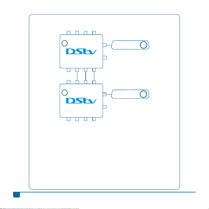
Connecting the DStv Switch (5-1) to two DStv Exploras
(E36B Angola and Mozambique only)
H/L V/L H/H V/H
1
1 2 3 4
H/L V/L H/H V/H
2
1 2 3 4
This installation requires a DStv Switch per DStv Explora. The DStv Switch
(5-1) can only be connected to one DStv Explora at any one time.
• Once the first switch has been connected to the satellite dish, connect
output A or B on the first switch to the input labelled UNICABLE™ IN on
the back of your first DStv Explora.
• Then, using the provided cables, connect the first DStv Switch to a second
DStv Switch. Connect the outputs labelled 2, 3 and 4 on the first switch,
to the inputs marked V/L, H/H and V/H on the second switch.
• Once the DStv Switches have been connected, connect output A or B on
the second switch to the input labelled UNICABLE™ IN on the back of
your second DStv Explora.
A
B
A
B
DStv Explora
DStv Explora
1
2
8
DStv Switch - User Guide
Page 11
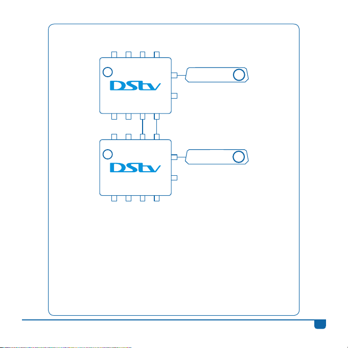
Connecting the DStv Switch (5-1) to two DStv Exploras (E36B)
H/L V/L H/H V/H
1
1 2 3 4
H/L V/L H/H V/H
2
1 2 3 4
This installation requires a DStv Switch per DStv Explora. The DStv Switch
(5-1) can only be connected to one DStv Explora at any one time.
• Once the first switch has been connected to the satellite dish, connect
output A or B on the first switch to the input labelled UNICABLE™ IN on
the back of your first DStv Explora.
• Then, using the provided cables, connect the first DStv Switch to a second
DStv Switch. Connect the outputs labelled 3 and 4 on the first switch, to
the inputs marked H/H and V/H on the second switch.
• Once the DStv Switches have been connected, connect output A or B on
the second switch to the input labelled UNICABLE™ IN on the back of
your second DStv Explora.
A
B
A
B
DStv Explora
DStv Explora
1
2
DStv Switch - User Guide
9
Page 12
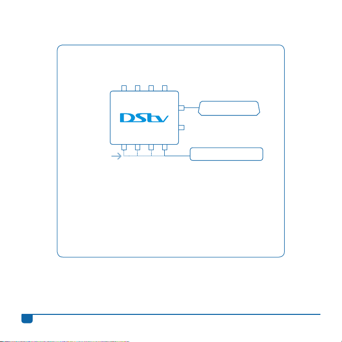
Connecting the DStv Switch (5-1) to one
DStv Explora and one to four Single View Decoders
H/L V/L H/H V/H
A
B
1 2 3 4
Use any
one of the
outputs.
• Once the switch has been connected to the satellite dish,
use the supplied cable and connect output A or B on the
switch to the input labelled UNICABLE™ IN on the back of
your DStv Explora.
• Then connect the outputs labelled 1 to 4 on the switch to the
satellite inputs on the back of the Single View Decoder(s).
DStv Explora
Single View Decoder(s)
10
DStv Switch - User Guide
Page 13
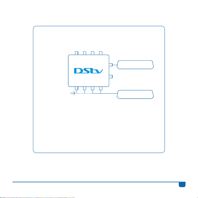
Connecting the DStv Switch (5-1) to one DStv Explora
and one 2 Tuner Decoder
H/L V/L H/H V/H
A
DStv Explora
Use a
combination of
any two outputs.
• Once the switch has been connected to the satellite dish,
use the supplied cable and connect output A or B on the
switch to the input labelled UNICABLE™ IN on the back of
your DStv Explora.
• Then connect any two outputs (labelled 1 to 4) on
DStv Switch - User Guide
B
1 2 3 4
Decoder Models:
2P, 2U, SD PVR &
Dual View
2 Tuner Decoder
the switch to the satellite inputs on the back of the 2 Tuner
Decoder (like a Dual View, SD PVR, HD PVR 2P or HD PVR 2U).
11
Page 14
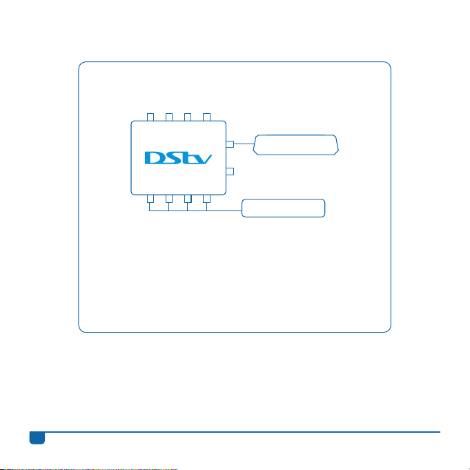
Connecting the DStv Switch (5-1) to one DStv Explora
and one 4 Tuner HD PVR
H/L V/L H/H V/H
A
B
1 2 3 4
DStv Explora
4 Tuner HD PVR
• Once the switch has been connected to the satellite dish,
use the supplied cable and connect output A or B on the
switch to the input labelled UNICABLE™ IN on the back of
your DStv Explora.
• Then connect the outputs labelled 1 to 4 on the switch to the
satellite inputs on the back of the 4 Tuner HD PVR.
Information correct at time of going to print. For updated information, go to www.dstv.com (the “DStv website”).
In the event of conflict between this information and the information on the DStv website, the information on the DStv website will prevail.
e&oe (August 2013, V2.7)
12
DStv Switch - User Guide
Page 15

Call Centres (open 7am - 11pm daily)
Johannesburg (011) 289 2222
Pretoria (012) 422 2222
Ca pe To wn (021) 508 2222
Durban (031) 710 2222
Port Elizabeth (041) 395 2222
Bloemfontein (051) 503 2222
Mobile 083 900 DSTV ( 3788) VAS rates apply
Also find us on
www.dstv.com
Page 16

 Loading...