

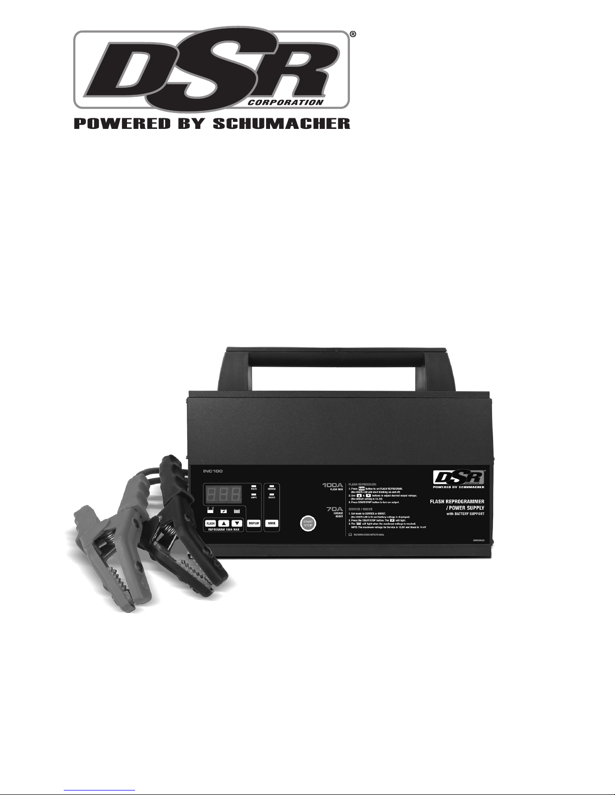
DSR INC100 Owner's Manual
0099001771-03
MODEL / MODELO / MODÈLE :
INC100
100A Flash Reprogrammer / Power Supply
with Battery Support
Reprogramador Flash de 100 A /
Fuente de alimentación con soporte de batería
Reprogrammation Flash 100A / source
d’alimentation électrique avec batterie d’appui.
PLEASE SAVE THIS OWNER’S MANUAL AND READ BEFORE EACH USE.
This manual will explain how to use the unit safely and effectively. Please read
and follow these instructions and precautions carefully.
POR FAVOR GUARDE ESTE MANUAL DEL PROPIETARIO Y LEER ANTES
DE CADA USO. En este manual se explica cómo utilizar la unidad con seguridad
y ecacia. Por favor, lea y siga las siguientes instrucciones y precauciones.
VEILLEZ A CONSERVER CES INSTRUCTIONS ET LES LIRE AVANT CHAQUE
UTILISATION. Ce guide vous montrera comment utiliser l'unité efcacement et
en toute sécurité. Veuillez lire et suivre ces instructions et précautions.
OWNERS MANUAL
MANUAL DEL USUARIO
MANUEL D’UTILISATION

• 2 •
1. IMPORTANT SAFETY INSTRUCTIONS
SAVE THESE INSTRUCTIONS.
SAVE THESE INSTRUCTIONS –
This manual contains important safety
and operating instructions.
WARNING:
RISK OF ELECTRIC SHOCK OR FIRE.
1.1 Keep out of reach of children.
1.2 Do not expose the unit to rain or snow.
1.3 Use of an attachment not recommended
or sold by the manufacturer may result
in a risk of re, electric shock or injury to
persons.
1.4 To reduce the risk of damage to electric
plug and cord, pull by the plug rather than
the cord when disconnecting the unit.
1.5 An extension cord should not be used
unless absolutely necessary. Use of
improper extension cord could result
in a risk of re and electric shock. If an
extension cord must be used, make sure:
• The pins on plug of extension cord are
the same number, size and shape as
those of plug on the unit.
• The extension cord is properly wired and
in good electrical condition
• The wire size is large enough for AC
ampere rating of the unit, as specied in
section 8.
1.6 Do not operate the unit with a damaged
cord or plug – replace the cord or plug
immediately.
1.7 Do not operate the unit if it has received
a sharp blow, been dropped, or otherwise
damaged in any way; take it to a qualied
serviceman.
1.8 Do not disassemble the unit; take it to
a qualied serviceman when service or
repair is required. Incorrect reassembly
may result in a risk of electric shock or re.
1.9 To reduce risk of electric shock, unplug
the unit from the outlet before attempting
any maintenance or cleaning. Turning off
controls will not reduce this risk.
1.10 WARNING:
RISK OF EXPLOSIVE GASES.
a. WORKING IN VICINITY OF A LEAD-
ACID BATTERY IS DANGEROUS.
BATTERIES GENERATE EXPLOSIVE
GASES DURING NORMAL BATTERY
OPERATION. FOR THIS REASON, IT IS
OF UTMOST IMPORTANCE THAT YOU
FOLLOW THE INSTRUCTIONS EACH
TIME YOU USE THE UNIT.
b. To reduce risk of battery explosion,
follow these instructions and those
published by battery manufacturer
and manufacturer of any equipment
you intend to use in vicinity of battery.
Review cautionary markings on these
products and on engine.
2. PERSONAL SAFETY PRECAUTIONS
WARNING:
RISK OF EXPLOSIVE GASES.
2.1 Consider having someone close enough
by to come to your aid when you work
near a lead-acid battery.
2.2 Have plenty of fresh water and soap
nearby in case battery acid contacts skin,
clothing, or eyes.
2.3 Wear complete eye protection and
clothing protection. Avoid touching eyes
while working near battery.
2.4 If battery acid contacts skin or clothing,
wash immediately with soap and water.
If acid enters eye, immediately ood
eye with running cold water for at least
10 minutes and get medical attention
immediately.
2.5 NEVER smoke or allow a spark or ame
in vicinity of battery or engine.
2.6 Be extra cautious, to reduce risk of
dropping a metal tool onto battery. It might
spark or short-circuit battery or other
electrical part that may cause explosion.
2.7 Remove personal metal items such as
rings, bracelets, necklaces, and watches
when working with a lead-acid battery. A
lead-acid battery can produce a shortcircuit current high enough to weld a ring
or the like to metal, causing a severe burn.
2.8 Use unit for only LEAD-ACID rechargeable
batteries. It is not intended to supply power
to a low voltage electrical system other
than in a starter-motor application.
2.9 NEVER use with a frozen battery.
2.10 WARNING: This product contains one
or more chemicals known to the State
of California to cause cancer and birth
defects or other reproductive harm.

• 3 •
3. PREPARING TO USE THE UNIT WITH A BATTERY
WARNING: RISK OF CONTACT WITH
BATTERY ACID. BATTERY ACID IS A
HIGHLY CORROSIVE SULFURIC ACID.
3.1 If necessary to remove the battery from
the vehicle, always remove the grounded
terminal from battery rst. Make sure all
accessories in the vehicle are off, so as
not to cause an arc.
3.2 Be sure area around battery is well
ventilated while using the unit.
3.3 Clean battery terminals. Be careful to
keep corrosion from coming in contact
with eyes.
3.4 Add distilled water in each cell until
battery acid reaches level specied by
battery manufacturer. Do not overll. For a
battery without removable cell caps, such
as valve regulated lead acid batteries,
carefully follow manufacturer’s recharging
instructions.
3.5 Study all battery manufacturer’s specic
precautions while using the unit with
a battery.
3.6 Determine the voltage of the battery by
referring to the car owner’s manual and
make sure that the battery is a 12V rated
battery. The unit is designed for 12V
batteries only.
3.7 Make sure that the unit's cable clips make
tight connections.
4. UNIT LOCATION
WARNING: RISK OF EXPLOSION
AND CONTACT WITH BATTERY ACID.
4.1 Locate the unit as far away from battery
as DC cables permit.
4.2 Never place the unit directly above the
battery; gases from battery will corrode
and damage the unit.
4.3 Never allow battery acid to drip on the unit
when reading electrolyte specic gravity
or lling battery.
4.4 Do not operate the unit in a closed-in area
or restrict ventilation in any way.
4.5 Do not set a battery on top of the unit.
5. DC CONNECTION PRECAUTIONS
5.1 Connect and disconnect DC output clips
only after setting any switches to “off”
position and removing AC cord from
electric outlet. Never allow the clips of the
unit to touch each other.
5.2 Attach clips to battery and chassis, as
indicated in sections 6 and 7.
6. FOLLOW THESE STEPS WHEN BATTERY IS INSTALLED IN VEHICLE
WARNING: A SPARK NEAR THE
BATTERY MAY CAUSE A BATTERY
EXPLOSION. TO REDUCE THE RISK OF
A SPARK NEAR THE BATTERY:
6.1 Position AC and DC cords to reduce risk
of damage by hood, door, or moving
engine part.
6.2 Stay clear of fan blades, belts, pulleys, and
other parts that can cause injury to persons.
6.3 Check polarity of battery posts. POSITIVE
(POS, P, +) battery post usually has larger
diameter than NEGATIVE (NEG, N,–) post.
6.4 Determine which post of battery is
grounded (connected) to the chassis. If
negative post is grounded to chassis (as
in most vehicles), see (6.5). If positive
post is grounded to the chassis, see (6.6).
6.5 For negative-grounded vehicle, connect
POSITIVE (RED) clip from the unit to
POSITIVE (POS, P, +) ungrounded post
of battery. Connect NEGATIVE (BLACK)
clip to vehicle chassis or engine block
away from battery. Do not connect clip to
carburetor, fuel lines, or sheet-metal body
parts. Connect to a heavy gauge metal
part of the frame or engine block.
6.6 For positive-grounded vehicle, connect
NEGATIVE (BLACK) clip from the unit
to NEGATIVE (NEG, N, –) ungrounded
post of battery. Connect POSITIVE (RED)
clip to vehicle chassis or engine block
away from battery. Do not connect clip to
carburetor, fuel lines, or sheet-metal body
parts. Connect to a heavy gauge metal
part of the frame or engine block.
6.7 Connect the unit's AC supply cord to
electrical outlet and press the START/
STOP button to turn the output on.
6.8 When disconnecting the unit, press the
START/STOP button to turn the output off,
disconnect the AC cord, remove the clip
from the vehicle chassis and then remove
the clip from the battery terminal.

• 4 •
7. FOLLOW THESE STEPS WHEN BATTERY IS OUTSIDE VEHICLE
WARNING: A SPARK NEAR THE
BATTERY MAY CAUSE A BATTERY
EXPLOSION. TO REDUCE THE RISK OF
A SPARK NEAR THE BATTERY:
7.1 Check polarity of battery posts. POSITIVE
(POS, P, +) battery post usually has a larger
diameter than NEGATIVE (NEG, N, –) post.
7.2 Attach at least a 24-inch long 4-gauge
(AWG) insulated battery cable to
NEGATIVE (NEG, N, –) battery post.
7.3 Connect POSITIVE (RED) clip to
POSITIVE (POS, P, +) post of battery.
7.4 Position yourself and free end of cable as
far away from battery as possible – then
connect NEGATIVE (BLACK) clip to free
end of cable.
7.5 Do not face battery when making nal
connection.
7.6 Connect the unit's AC supply cord to
electrical outlet and press the START/
STOP button to turn the output on.
7.7 When disconnecting the unit, press the
START/STOP button to turn the output off,
disconnect the AC cord, remove the clip
from the cable attached to the negative
battery terminal and then remove the clip
from the positive battery terminal.
8. GROUNDING AND AC POWER CORD CONNECTIONS
WARNING:
RISK OF ELECTRIC SHOCK OR FIRE.
8.1 This unit is for use on a nominal 120 volt
circuit and has a grounded plug. The unit
must be grounded, to reduce the risk of
electric shock. The plug must be plugged
into an outlet that is properly installed and
grounded in accordance with all local codes
and ordinances. The plug pins must t
the receptacle (outlet). Do not use with an
ungrounded system.
8.2 DANGER: Never alter the AC cord or
plug provided – if it does not t the outlet,
have a proper grounded outlet installed
by a qualied electrician. An improper
connection can result in a risk of an
electric shock or electrocution.
NOTE: Pursuant to Canadian
Regulations, use of an adapter plug
is not allowed in Canada. Use of an
adapter plug in the United States is not
recommended and should not be used.
8.3 USING AN EXTENSION CORD
The use of an extension cord is not
recommended. If you must use an
extension cord, follow these guidelines:
• Pins on plug of extension cord must be
the same number, size, and shape as
those of plug on the unit.
• Ensure that the extension cord is properly
wired and in good electrical condition.
• Wire size must be large enough for the
AC ampere rating of unit as specied:
▫ 100 feet (30.5 meters) long or less –
use a 12 gauge (3.31 mm2)
extension cord.
▫ Over 100 feet (30.5 meters) long –
use an 8 gauge (8.36 mm2)
extension cord.
• 5 •
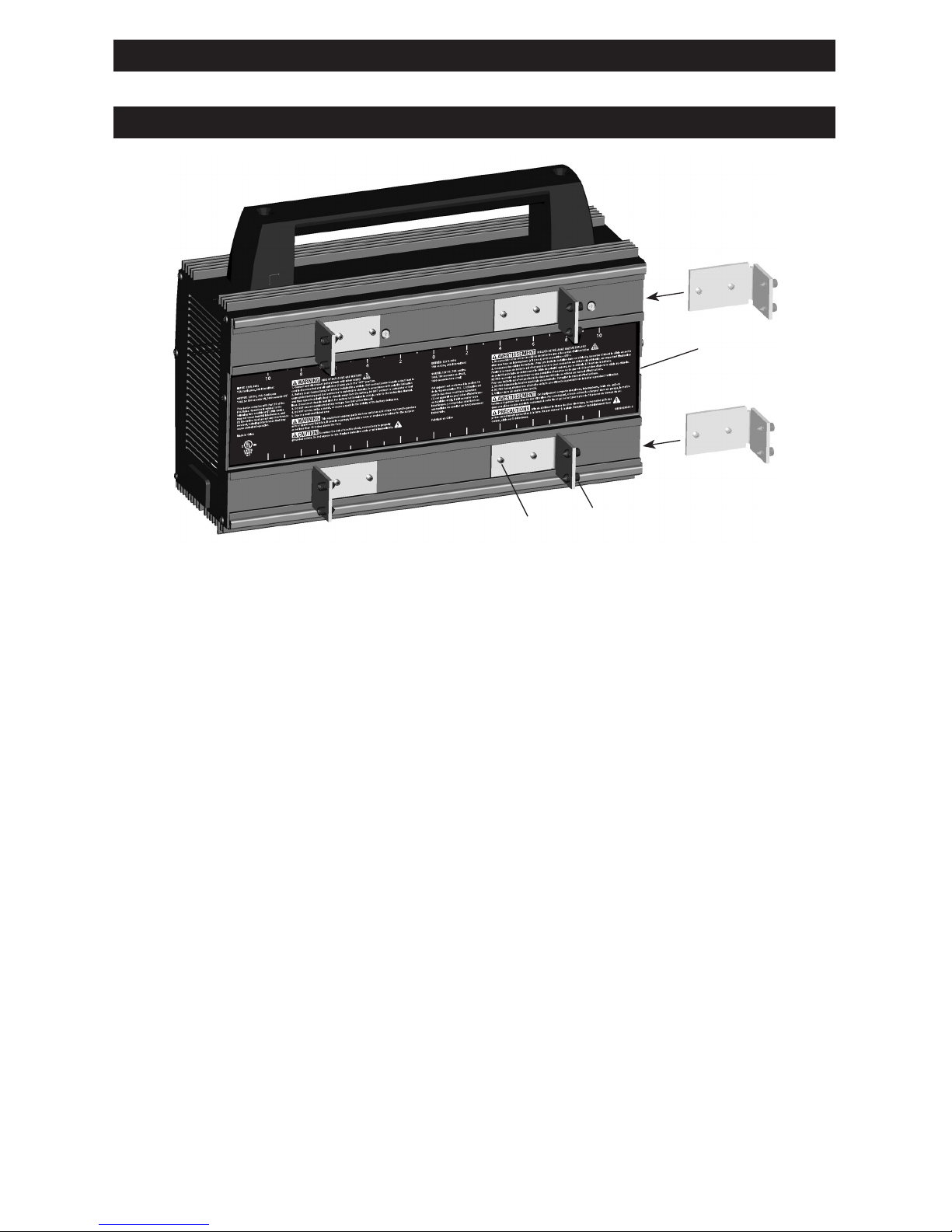
9. ASSEMBLY INSTRUCTIONS
9.1 Remove all cord wraps and uncoil the cables prior to using the unit.
10. MOUNTING INSTRUCTIONS
1
3
4
2
To permanently mount the unit, use the
following instructions:
10.1 Slide all 4 brackets (Item 1) into the track
on the back, from the right side, as shown
above. Make sure the set screws (Item 2)
are unscrewed enough so they do not
scratch the surface of the housing.
10.2 Measure what you are mounting the
unit to before deciding where to locate
the brackets (add an additional ¼ to ½
inch). Use the ruler on the label (Item
3) to mount the brackets (Item 1) in the
correct position (position each bracket an
equal distance from the center of the unit).
Note that the inches shown are for both
bracket dimensions combined (meaning
the dimensions are doubled), this is for
easier reference. Make sure the ¼-28 set
screws (Item 4) are unscrewed enough
so the pointed end is almost ush with the
bracket. Mount the brackets (Item 1) by
tightening all 8 set screws (Item 2) to 14
in/lb (1.6 n/m) of torque.
10.3 Lift the unit by its handle and set it against
your mounting location, tighten the set
screws (Item 4) to 66 in/lb (7.5 n/m) of
torque to secure the brackets (Item 1),
starting with the top two brackets rst.
• 6 •
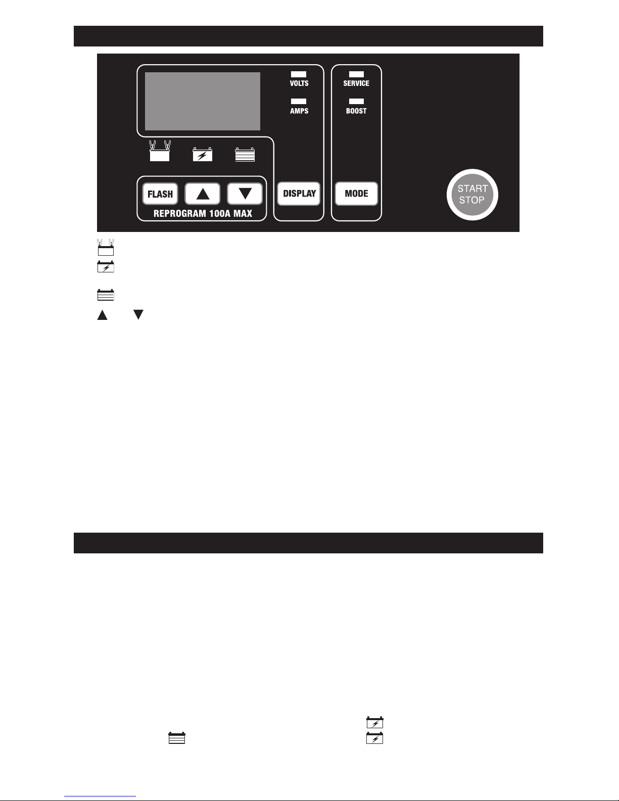
11. CONTROL PANEL
LED (yellow/orange) – Lights when the battery is properly connected.
LED (yellow/orange) – Lights when output begins; turns off when maximum voltage
is reached.
LED (green) – Lights when maximum voltage is reached.
and (UP and DOWN) Buttons
Use these buttons to set the voltage needed for FLASH REPROGRAM.
START/STOP Button – This starts and stops all modes.
Digital Display – Gives a digital indication of voltage or amperes, depending on the
display function chosen.
Display Button – Press to set the function of the digital display to one of the following:
• VOLTS (Voltmeter)
The voltmeter indicates the voltage at the load/battery terminals.
If the reading is 12.8 volts or more when output is off, the battery is charged.
• AMPS (Ammeter)
The ammeter indicates the amount of current, measured in amps, that is being drawn by
the load/battery (± 2 amps).
Mode Button – Use this button to select between SERVICE and BOOST modes.
See Operating Instructions for details of these modes.
Flash Reprogram Button – Press to select the FLASH REPROGRAM function.
See Operating Instructions for details of this function.
12. OPERATING INSTRUCTIONS
Application Information
This unit can be used to support 12V batteries with rated capacities of 12 Ah to 111 Ah.
Unit Operation
NOTE: Once Service, Boost or Flash Reprogram has started, the buttons will not work until you
turn off the output, with the exception of the START/STOP button. When the display shows ,
no buttons will work for ve seconds as the unit automatically goes back to the default settings.
Service Mode
Use to prevent the battery from being discharged during service and in the showroom.
1. Connect the battery and AC power, following the precautions listed in sections 5, 6 and 7.
2. Set the MODE to SERVICE.
3. The VOLTS LED will light, and the display will show battery voltage.
4. Press the START/STOP button. The yellow/orange LED will light.
5. The green LED will light and the yellow/orange LED will turn off when the
maximum voltage is reached.
NOTE: Maximum voltage for Service Mode is 13.5V.

• 7 •
Boost Mode
For quickly adding energy to a severely discharged or large capacity battery.
NOTE: Do not leave in Boost mode for extended periods of time. When connected for long
periods of time, Service Mode is recommended.
1. Connect the battery and AC power, following the precautions listed in sections 5, 6 and 7.
2. Set the MODE to BOOST.
3. The VOLTS LED will light, and the display will show battery voltage.
4. Press the START/STOP button. The yellow/orange LED will light.
5. The green LED will light and the yellow/orange LED will turn off when the
maximum voltage is reached.
NOTE: Maximum voltage for Boost Mode is 14.4V. Disconnect the unit when maximum
voltage has been reached, to avoid overheating of the battery.
100A Flash Reprogram
NOTE: Do not attempt to Flash Reprogram a vehicle that has a discharged or defective
battery. Make sure that the vehicle battery is in good condition and fully charged before
proceeding. In Flash Reprogram Mode, the unit is able to deliver 70A charging current
continuously, and to deliver up to 100A for three minutes.
1. Press the FLASH button.
2. The VOLTS LED will light, and the display will show the default setting 14.2V.
3. Press the and buttons to adjust to the voltage needed for the vehicle being
programmed (refer to OEM specications). Selected voltage is shown on the digital
display. The unit has a voltage range of 13 to 14.8, with a default of 14.2.
4. Press the START/STOP button.
5. When nished, press the START/STOP button to exit this mode.
Using the Battery Voltage Tester
Overview
This unit has a built-in voltmeter to measure your battery’s voltage. The unit does not
have a built in load tester. As such, a recently charged battery could have a temporarily
high voltage due to what is known as “surface charge”. The voltage of such a battery will
gradually drop during the period immediately after the charging system is disengaged.
Consequently, the tester could display inconsistent values for such a battery. For a more
accurate reading, the surface charge should be removed by temporarily creating a load on
the battery, such as by turning on lights or other accessories for a couple of minutes before
you read the display. Read it a couple of minutes after you have shut the headlights off.
Testing Sequence: There are seven basic steps required to test the battery state of charge:
NOTE: You cannot test the battery voltage while Flash Reprogram, Boost or Service
modes are active.
1. With the unit unplugged from the AC outlet, connect the unit to the battery, following the
instructions given in Sections 6 and 7.
2. Plug the unit's AC power cord into the AC outlet.
3. The yellow/orange LED will light if a properly connected battery is detected.
4. Conrm the yellow/orange LED is off.
5. Set the DISPLAY to VOLTS.
6. If the output is on, press the START/STOP button. If the output is already off, do not
press the START/STOP button.
7. Read the voltage on the digital display.
General Usage Notes
Fans – The unit is designed to control its cooling fans for efcient operation. It is normal for
the fans to start and stop as needed. Keep the area near the unit clear of obstructions to allow
the fans to operate efciently. NOTE: The unit has thermal protection, and it will shut down if it
gets too hot.
Voltage – The voltage displayed during output is the loading voltage and is usually higher
than the battery’s resting voltage.

• 8 •
13. MAINTENANCE INSTRUCTIONS
13.1 Before performing maintenance, unplug
and disconnect the unit (see sections 5.8
and 6.7).
13.2 After use, unplug the unit and use a dry
cloth to wipe all battery corrosion and
other dirt or oil from the terminals, cords,
and the case.
13.3 After every 100 hours or whenever
you see dust accumulating on the fan
blades, you should clean both fans using
compressed air (as shown). NOTE: Use
the compressed air on the fan blades
only. Do not blow dirt into the fan shaft or
bearing. These fans push a lot of air and
are precision balanced. Excessive dirt and
grime buildup will
cause the fan to be
unbalanced and wear
out quickly. If the
fans fail, the unit may
overheat and the
thermal protection
of the unit will shut it
down.
13.4 Ensure that all of the components are
in place and in good working condition,
including the plastic boots on the battery
clips.
13.5 Servicing does not require opening the unit,
as there are no user-serviceable parts.
14. MOVING AND STORAGE INSTRUCTIONS
14.1 If the unit is moved around the shop or
transported to another location, take care
to avoid/prevent damage to the cords,
clips and unit. Failure to do so could result
in personal injury or property damage. Do
not store the clips on the handle, clipped
together, on or around metal, or clipped
to cables.
14.2 Store the unit unplugged. The cord will
still conduct electricity until it is unplugged
from the outlet.
14.3 Store inside, in a dry, cool place).
15. TROUBLESHOOTING
PROBLEM POSSIBLE CAUSE SOLUTION
No display and the LEDs
are not lit.
Unit is not plugged in.
No power at the receptacle.
Plug the unit into an AC outlet.
Check for open fuse or circuit
breaker supplying AC outlet.
Display reads 0.0 volts. Clamps are not making
a good connection to the
battery.
Connections are reversed.
Battery is defective.
Check for poor connection to
battery and frame. Make sure
connection points are clean. Rock
clamps back and forth for a better
connection.
Unplug the unit and reverse
the clips.
Have battery checked.
The battery is connected
and the unit is on, but
there is no output.
Battery is severely
discharged (Service/Boost
modes only).
If your battery does not have 1
volt, you must press and hold
the START/STOP button for ve
seconds.
Unit has shut down or
will not turn on when
properly connected.
The unit has gotten too hot
and it has shut down.
The unit has thermal protection,
and it will shut down if it gets too
hot. Unplug the AC cord and let the
unit cool down. Make sure there is
nothing obstructing the air ow to
the fans, clean them as shown in
Maintenance Instructions.
The cooling fan is
making a rattling noise.
The fan has a buildup of dirt
and grime, causing it to be
unbalanced.
Blow the dirt and grime off the
fan blades using compressed
air as described in Maintenance
Instructions.

• 9 •
16. SPECIFICATIONS
Input .................................................................................. 120V~60Hz 15A Cont.; 24A Int.
Output:
Service mode .......................................................................................... 13.5V 0-70A
Boost mode ............................................................................................. 14.4V 0-70A
Reprogram mode ..................................................................... 13-14.8V 0-70A Cont.
100A Int. (180 sec. on; 1600 sec. off)
Weight ..................................................................................................................... 4.75 kg
Operating temperature .................................................... -20 °C – +40 °C (-4 °F– +104 °F)
Operating humidity ................................................................ 0 – 90% RH non-condensing
Working life (MTBF) ....................................................................................... 85,000 hours
17. REPLACEMENT PARTS
Battery cable, 3m (4 AWG) ........................................................................... 2299003103Z
Battery cable, 4m (2 AWG) ........................................................................... 2299003115Z
Battery cable, 5m (2 AWG) ........................................................................... 2299003116Z
18. BEFORE RETURNING FOR REPAIRS
If these solutions do not eliminate the problem,
or for more information about troubleshooting,
contact customer service for assistance:
services@schumacherelectric.com
www.batterychargers.com
or call 1-800-621-5485
Monday-Friday 7:00am to 5:00pm CST
For REPAIR OR RETURN, contact Customer Service at 1-800-621-5485. DO NOT SHIP
UNIT until you receive a RETURN MERCHANDISE AUTHORIZATION (RMA) number
from Customer Service at Schumacher Electric Corporation.

• 10 •
19. LIMITED WARRANTY
SCHUMACHER ELECTRIC CORPORATION, 801 BUSINESS CENTER DRIVE, MOUNT
PROSPECT, IL 60056-2179, MAKES THIS LIMITED WARRANTY TO THE ORIGINAL
RETAIL PURCHASER OF THIS PRODUCT. THIS LIMITED WARRANTY IS NOT
TRANSFERABLE OR ASSIGNABLE.
Schumacher Electric Corporation (the “Manufacturer”) warrants this Flash Reprogrammer/
Power Supply for one (1) year from the date of purchase at retail against defective
material or workmanship that may occur under normal use and care. If your unit is not free
from defective material or workmanship, Manufacturer’s obligation under this warranty
is solely to repair or replace your product with a new or reconditioned unit at the option
of the Manufacturer. It is the obligation of the purchaser to forward the unit, along with
proof of purchase and mailing charges prepaid to the Manufacturer or its authorized
representatives in order for repair or replacement to occur.
Manufacturer does not provide any warranty for any accessories used with this product
that are not manufactured by Schumacher Electric Corporation and approved for use
with this product. This Limited Warranty is void if the product is misused, subjected to
careless handling, repaired, or modied by anyone other than Manufacturer or if this
unit is resold through an unauthorized retailer.
Manufacturer makes no other warranties, including, but not limited to, express, implied
or statutory warranties, including without limitation, any implied warranty of merchantability or implied warranty of tness for a particular purpose. Further, Manufacturer
shall not be liable for any incidental, special or consequential damage claims incurred
by purchasers, users or others associated with this product, including, but not limited
to, lost prots, revenues, anticipated sales, business opportunities, goodwill, business
interruption and any other injury or damage. Any and all such warranties, other than the
limited warranty included herein, are hereby expressly disclaimed and excluded. Some
states do not allow the exclusion or limitation of incidental or consequential damages or
length of implied warranty, so the above limitations or exclusions may not apply to you.
This warranty gives you specic legal rights and it is possible you may have other rights
which vary from this warranty.
THIS LIMITED WARRANTY IS THE ONLY EXPRESS LIMITED WARRANTY AND
THE MANUFACTURER NEITHER ASSUMES OR AUTHORIZES ANYONE TO
ASSUME OR MAKE ANY OTHER OBLIGATION TOWARDS THE PRODUCT
OTHER THAN THIS WARRANTY.
Schumacher® and the Schumacher logo are registered trademarks
of Schumacher Electric Corporation.
 Loading...