

DSR DSR1020, DSR8020, DSR2020, DSR4020 Installer/user Manual

DSR® Switch
Installer/User Guide
For models: DSR1020, DSR2020, DSR4020, DSR8020
A vocent, the Avocent logo, The Power of Being There, DSR, DSView
and OSCAR are registered trademarks of Avocent Corporation or its
affiliates. All other marks are the property of their respective owners.
© 2004 Avocent Corporation. All rights reserved.
USA Notification
W arning: Changes or modifications to this unit no t expressly approved by the party responsible for compliance
could void the user’s authority to operate the equipment.
Note: This equipment has been tested and found to comply with the limits for a Class A digital device,
pursuant to Part 15 of the FCC Rules. These limits are designed to provide reasonable protection against
harmful interference when the equipment is operated in a commercial environment. This equipmen t generat es,
uses and can radiate radio frequency energy and, if not installed and used in accordance with the instruction
manual, may cause harmful interference to radio communications. Operation of this equipment is a re sidentia l
area is likely to cause harmful interference, in which case the use r will be required to correct the interference at
his/her own expense.
Japanese Approvals
Safety and EMC Standards
UL, FCC, cUL, ICES-003, CE, GS, VCCI, MIC, C-Tick, GOST

iii
List of Figures .................................................................................................................. v
List of Tables..................................................................................................................vii
Chapter 1: Product Overview.......................................................................................... 1
Features and Benefits.................................................................................................................1
Safety Precautions......................................................................................................................4
Chapter 2: Installation ..................................................................................................... 5
Installation Overview..................................................................................................................5
Getting Started...................................................... ......................................................................7
Connecting the DSR Switch Hardware.......................................................................................8
Verifying the Connections............................. ............................................................................10
Configuring DSView Software and Adjusting Mouse Settings.................................................10
Chapter 3: Local Port Operation................................................................................... 13
Controlling Your System at the Local Port ..............................................................................13
Viewing and Selecting Ports and Servers.................................................................................13
Navigating the OSCAR Interface..............................................................................................15
Configuring OSCAR Interface Menus......................................................................................17
Managing Server Tasks Using the OSCAR Interface...............................................................33
Chapter 4: Terminal Operations ................................................................................... 39
The Console Menu.................... ................................................... .............................................39
Other Console Main Menu Options..........................................................................................42
Appendices..................................................................................................................... 45
Appendix A: FLASH Upgrades.................................................................................................45
Appendix B: Using DSView Software Over a Modem Connection..........................................47
Appendix C: Using DSRIQ-SRL Modules ................................................................................48
Appendix D: UTP Cabling........................................................................................................52
Appendix E: Technical Specifications......................................................................................54
Appendix F: Sun Advanced Key Emulation..............................................................................56
Appendix G: Technical Support................................................................................................58
Index................................................................................................................................ 59
TABLE OF CONTENTS

iv DSR Switch Installer/User Guide

v
Figure 1.1: Example DSR Switch Configuration...............................................................................3
Figure 1.2: DSR Switch Model Comparison ......................................... ............................................3
Figure 2.1: Basic DSR Switch Configuration....................................................................................6
Figure 3.1: Main Dialog Box ..........................................................................................................13
Figure 3.2: Setup Dialog Box..........................................................................................................18
Figure 3.3: Names Dialog Box...................................................................... ..................................19
Figure 3.4: Name Modify Dialog Box.............................................................................................20
Figure 3.5: Devices Dialog Box......................................................................................................21
Figure 3.6: Device Modify Dialog Box ........................................................................................ ...22
Figure 3.7: Menu Dialog Box......................................... .................................................................23
Figure 3.8: Flag Dialog Box ...........................................................................................................24
Figure 3.9: Position Flag ................................................................................................................25
Figure 3.10: Broadcast Dialog Box ................................................................................................26
Figure 3.11: Scan Dialog Box.........................................................................................................27
Figure 3.12: Commands Dialog Box...............................................................................................29
Figure 3.13: Screen Saver Dialog Box............................................................................................30
Figure 3.14: Keyboard Dialog Box.................................................................................................32
Figure 3.15: Commands Dialog Box...............................................................................................33
Figure 3.16: User Status Dialog Box ..............................................................................................34
Figure 3.17: Disconnect Dialog Box...............................................................................................35
Figure 3.18: Version Dialog Box ....................................................................................................36
Figure 3.19: DSRIQ Selection Dialog Box......................................................................................37
Figure 3.20: DSRIQ Version Dialog Box........................................................................................37
Figure 4.1: Console Main Menu......................................................................................................40
Figure 4.2: Network Configuration Menu..................................................... ... ...............................41
LIST OF FIGURES

vi DSR Switch Installer/User Guide

vii
Table 3.1: OSCAR Interface Status Symbols............... ... .................................................................14
Table 3.2: OSCAR Interface Navigation Basics................ ..............................................................15
Table 3.3: Setup Features to Configure the OSCAR Interface........................................................17
Table 3.4: OSCAR Interface Status Flags .......................................................................................24
Table 3.5: Commands to Manage Routine Tasks for Your Target Device(s)..................................33
Table C.1: DSRIQ-SRL Module Pinouts .........................................................................................51
Table D.1: UTP Wiring Standards ..................................................................................................52
Table E.1: DSR Switch Product Specifications ...............................................................................54
Table F.1: Sun Key Emulation.........................................................................................................56
Table F.2: PS/2-to-USB Keyboard Mappings .................................................................................57
LIST OF TABLES

viii DSR Switch Installer/User Guide

1
CHAPTER
1
Product Overview
Features and Benefits
Avocent DSR® switches combine analog and digital technology to provide flexible, centralized
control of data center servers and facilitate the OA&M (operations, activation and maintenance) of
remote branch offices where trained operators may be unavailable. They provide enterprise
customers with a significant reduction of cable volume, secure remote access and flexible server
management from anywhere at anytime.
Each DSR switch model consists of a rack mountable keyboard, video and mouse (KVM) switch,
configurable for analog (local) or digital ( remote) connectivity. Video resolutions are supported
up to1280 x 1024 for remote users. Enhanced vide o quality o f up to 1600 x 1200 is available to
local users via the video port.
The DSR switch has user peripheral ports for PS/2 and USB keyboards and mice and an SPC port
that may be used to connect to an SPC power control device. An SPC device is an 8- or 16-outlet
device that can be used to control the power state of any attached target devices using the
DS software.
The DSR switches work over standard LAN connections. Users can access target devices
across a 1000BaseT LAN port that is used to establish an Ethernet connection, or directly
through a local port. Each DSR switch model includes a MODEM port that supports V.34, V.90
or V.92-compatible modems that may be used to access the switch when an Ethernet
connection is not available.
The IP-based DSR switches give you flexible target device management control from anywhere in
the world.
Reduce cable bulk
With server densities continually increasing, cable bulk remains a major concern for network
administrators.The DSR switches significantly reduce KVM cable volume in the rack by utilizing
the innovative DSRIQ module and single, industry-standard Unshielded Twisted Pair (UTP) CAT
5 cabling. This allows a higher server density while providing greater airflow and cooling capacity.
The DSRIQ module is powered directly from the target device and provides Keep Alive
functionality when the DSR switch is not powered.

2 DSR Switch Installer/User Guide
The DSRIQ-SRL (serial) module is a DCE device that provides the primary interface between a
serial device and a DSR switch. It provides VT100 terminal emulation, break suppression and port
history in a compact, convenient module.
Access the DSR switch via network connection
No special software or drivers are required on the attached, or client, computers.
NOTE: The client connects to the server housing the DSView® management software using an Internet browser.
For modem access, you must install DSR Remote Operations software included on the DSView software
CD-ROM (see the DSView Installer/User Guide for more information).
Users access the DSR switch and all attached systems via Ethernet or using a V.34, V.90 or V.92
modem from a client computer, such as a PC. Clients can be located anywhere a valid network
connection exists.
Simple access to any target device
When a user accesses the DSView Server software, a listing of all target devices to which the user
has permission to view and manage is displayed. When a user selects a target device from the list,
the video of the selected target device is displayed in a Video Viewer window.
Chapter 1: Product Overview 3
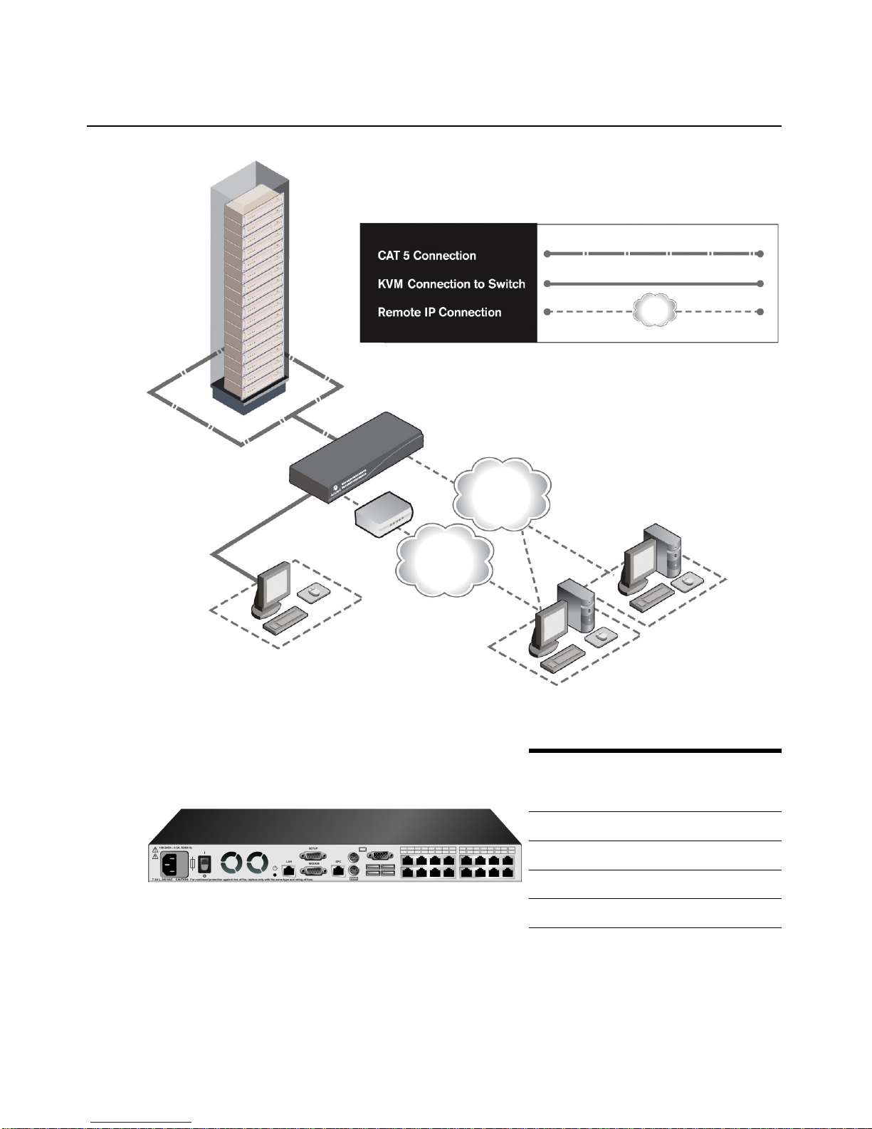
Figure 1.1: Example DSR Switch Configuration
Figure 1.2: DSR Switch Model Comparison
Digital User
(Computer with Internet browser)
Analog User
(OSCAR Graphical
User Interface)
DSR Switch
Modem
Telephone
Network
Ethernet
DSView Server
Software
Model
Number
of
Servers
Digital
paths
Analog
User
DSR1020 16 1 1
DSR2020 16 2 1
DSR4020 16 4 1
DSR8020 16 8 1
DSR Switch

4 DSR Switch Installer/User Guide
Safety Precautions
To avoid potential video and/or keyboard problems when using Avocent products:
• If the building has 3-phase AC power , ensure that th e computer and monitor are on the same phase.
For best results, they should be on the same circuit.
To avoid potentially fatal shock hazard and possible damage to equipment, please observe the
following precautions:
• Do not use a 2-wire power cord in any Avocent product configuration.
• T est AC ou tlets at th e tar get device and mo nitor for proper polarity and gr ounding .
• Use only with grounded outlets at bo th the tar get device and monitor. When using a backup
Uninterruptible Power Supply (UPS), power t he target device, the monitor and the DSR switch from
the UPS.
NOTE: The AC inlet is the main power disconnect.
Rack mount safety considerations
• Elevated Ambient Temperature: If installed in a closed rack assembly, the operating temperature of
the rack environment may be greater than room ambient. Use care not to exceed the rated maximum
ambient temperature of the switch.
• Reduced Air Flow: Installation of the equipment in a rack should be such that the amount of airflow
required for safe operation of the equipment is not compromised.
• Mechanical Loading: Mounting of the equipment in the rack should be such that a hazardous
condition is not achieved due to uneven mechanical loading.
• Circuit Overloading: Consideration should be given to the connection of the equipment to the supply
circuit and the effect that ov erloading of ci rcuits might h ave on overcurrent protection and supp ly
wiring. Consider equipment nameplate r atings for maximu m current.
• Reliable Earthing: Reliable earthing of rack mounted equi pment should be maintain ed. Pay
particular attention to supply connections other than direct connections to the branch circuit (for
example, use of power strips).

5
CHAPTER
2
Installation
The DSR switching system requires connectivity to a server running the DSView Server software.
DSView software allows a user to view and control target devices (one at a time) attached to the
DSR switching system. For more information on the DSView software, see the DSView
Installer/User Guide.
The DSR switching system transmits keyboard, video and mouse (KVM) information between
operators and target devices attached to the DSR switch over a network using either an Ethernet
connection or a modem connection.
The DSR switch uses TCP/IP for communication over Ethernet. Although 10BaseT Ethernet may
be used, Avocent recommends a dedicated, switched 100BaseT network, or even a
1000BaseT network.
The DSR switch uses the Point-to-Point Protocol (PPP) for communication over a V.34, V.90 or
V.92 modem.
Installation Overview
The general procedure for setting up and installing the DSR switch is as follows:
• Unpack the DSR switch and verify that all components are present and in good condition. See
the Getting S tarted section in this chapter.
• Make all hardware connections between the power source, DSR switch, target devices,
optional SPC device, the Ethernet and the optional modem connection. See the Connecting the
DSR Switch Hardware section.
• Turn on the power and verify that all connections are working. See the Verifying the
Connections section.
• If you are configuring the DSR switch using the console menu interface, do that at this point.
See Chapter 4 for more information.
• Use the DSView Server software to configure the DSR switch. See the DSView Installer/User
Guide for detailed instructions.
• Make the appropriate mouse setting adjustments. See the Adjusting mouse settings on target
devices section.
6 DSR Switch Installer/User Guide
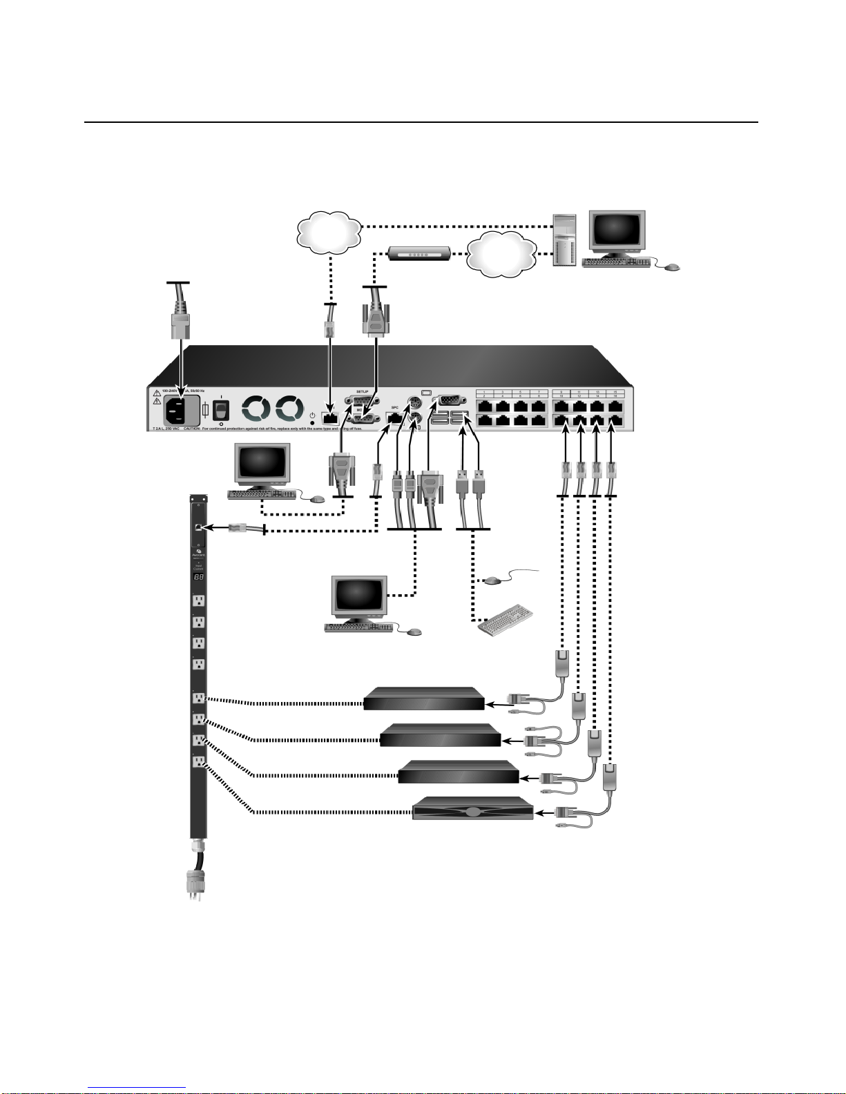
The following diagram illustrates one possible configuration for your DSR switch .
Figure 2.1: Basic DSR Switch Configuration
Digital User
Servers 1-16
DSR1020 Switch
Power
Telephone
Network
Ethernet
Internet Connection
Cord
Ethernet and/or
Modem
Setup
Analog User
SPC Port
Connection
KVM
Connections
Ports
1-16
CAT 5
Cable
USB
SPC
Power Control
Device
DSRIQ Modules
PS/2, USB, Sun and
serial adaptors
are available
PS/2
Port

Chapter 2: Installation 7
Setting up your network
The DSR switching system uses IP addresses to uniquely identify the switch and the target devices.
The DSR switch supports both Dynamic Host Configuration Protocol (DHCP) and static IP
addressing. Avocent recommends that IP addresses be reserved for each switch and that they
remain static while the DSR switches are connected to the network. For additional information on
setting up the DSR switch using the DSView Server software, and for information on how the DSR
switch uses TCP/IP, see the DSView Installer/User Guide.
Getting Started
Before installing your DSR switch, refer to the following lists to ensure you have all items that shipped
with the DSR switch, as well as other items necessary for proper installation.
Supplied with the DSR switch
• Local country power cord
• Rack mounting brackets
• Null modem cable
• DSR Installer/User Guide (this manual)
• DSR Quick Installation Guide
Additional items needed
• One DSRIQ module per target server or DSRIQ-SRL module per serial device
• One CAT 5 patch cable per DSRIQ module (4-pair UTP, up to 10 meters)
• One CAT 5 patch cable for network connecti vit y (4-pair UTP, up to 10 meters)
• DSView software
• (Optional) V.34, V.90 or V.92-co mpat ibl e modem and cables
• (Optional) SPC power control device
8 DSR Switch Installer/User Guide
Connecting the DSR Switch Hardware
NOTE: The DSR switch may be rack mounted in a 1U configuration. The DSR switch does not support a
0U configuration.
To connect and power up your DSR switch:
1. Power down the target device(s) that will be part of your DSR switching system. Locate the
power cord that came with the DSR switch. Plug one end into the power socket on the rear of
the DSR switch. Plug the other end into an appropriate AC wall outlet.
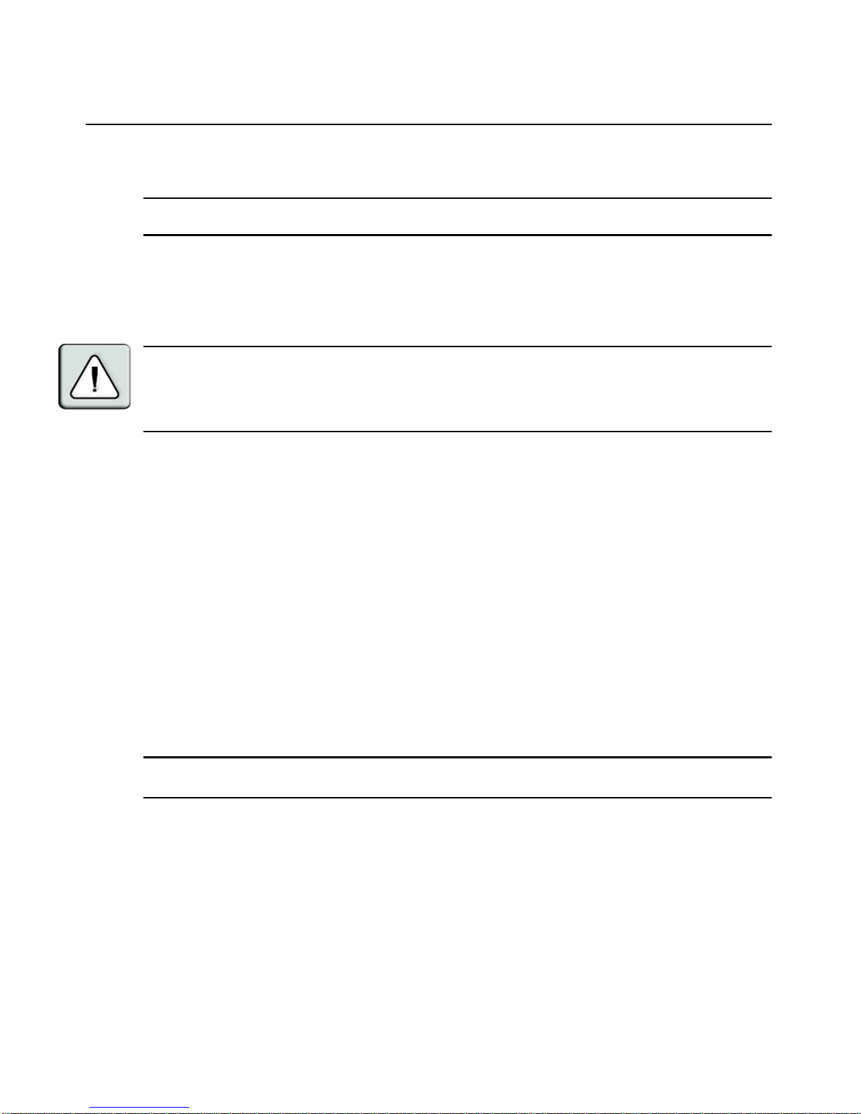
WARNING: To reduce the risk of electric shock or damage to your equipment:
- Do not disable the power cord gro unding plug. The grounding plug is an important safety feature.
- Plug the power cord into a grounded (earthed) outlet that is easily accessible at all times.
- Disconnect the power from the switch by unplugging the power cord from either the electrical outlet or
the appliance.
2. Plug your VGA monitor and either PS/2 or USB keyboard and mouse cables into appropriately
labeled DSR switch ports. You must install both a keyboard and mouse on the local port or the
keyboard will not initialize properly.
3. Choose an available numbered port on the rear of your DSR switch. Plug one end of a CAT 5
patch cable (4-pair, up to 10 meters) into the selected port and plug the other end into the RJ-45
connector of a DSRIQ module.
4. Plug the DSRIQ module into the appropriate ports on the back of the target server. Repeat this
procedure for all servers that are to be connected to the DSR switch. See To connect a DSRIQ
module to a server and To connect a DSRIQ module to a serial device for
more information.
5. Plug a CAT 5 patch cable from your Ethernet network into the LAN port on the back of your
DSR switch. Network users will access the DSR switch through this port.
6. (Optional) The DSR switch may also be accessed using a ITU V.92, V.90 or V.34-compatible
modem. Plug the 9-pin serial cable into the MODEM port on the back of your DSR switch.
Plug the other end into the connector on the modem.
NOTE: Using a modem connection instead of a LAN connection will limit the performance capability of your
DSR switch.
7. (Optional) Plug one end of the cable supplied with the SPC power control device into the SPC
port on the DSR switch and plug the other end into an SPC device. Plug the power cords from
the target servers into the SPC device power outlets. Plug the SPC device into an appropriate
AC wall outlet. Plug the SPC device into an appropriate AC wall outlet.
8. If you will be configuring the DSR switch using the console menu interface, connect a terminal
or PC running terminal emulation software (such as HyperTerminal
®
) to the SETUP port on
the back panel of the DSR switch using the supplied null modem cable. The terminal should be
set to 9600 bits per second (bps), 8 bits, 1 stop bit, no parity and no flow control. Otherwise,
proceed to the next step.

Chapter 2: Installation 9
9. Power up each target device and then power up the DSR switch. After approximately one
minute, the switch completes initialization and displays the OSCAR
®
graphical user interface
Free tag on the local port monitor.
10. Use the DSView software to configure the switch. See the DSView Installer/User Guide for
detailed instructions.
To connect a DSRIQ module to a server:
1. Attach the appropriately color-coded connectors of a DSRIQ module to the keyboard, monitor
and mouse ports on the server you will be connecting to this DSR switch.
2. Attach one end of the CAT 5 patch cable to the RJ-45 connector on the DSRIQ module.
Connect the other end of the CAT 5 patch cable to the desired port on the back of your
DSR switch.
3. Repeat this procedure for all servers you wish to attach.
NOTE: When connecting a Sun DSRIQ module, you must use a multi-sync monitor in the local port to
accommodate Sun computers that support both VGA and sync-on-green or composite sync.
To connect a DSRIQ module to a serial device:
1. Attach the DSRIQ-SRL module 9-pin serial connector to the serial port of the device to be
connected to your DSR switch.
2. Attach one end of the CAT 5 patch cable to the RJ-45 connector on the DSRIQ-SRL module.
Connect the other end of the CAT 5 patch cable to the desired port on the back of your
DSR switch.
NOTE: The DSRIQ-SRL module is a DCE device and only supports VT100 terminal emulation.
3. Connect the power supply to the power connector on your DSRIQ-SRL module. The cable
expander can be used to power up to four DSRIQ-SRL modules from a single power supply.
4. Connect the DSRIQ-SRL module power supply to an appropriate AC wall outlet. Power up
your serial device. See Appendix C for more infor mation on DSRIQ-SRL modules.

10 DSR Switch Installer/User Guide
Verifying the Connections
DSR switch
The front panel of the DSR switch features two LEDs indicating the Ethernet connection. The top
green LED is the Link indicator. It will illuminate when a valid connection to the network is
established and blink when there is activity on the port. The lower amber/green LED, labeled 100/
1000, will indicate that you are communicating at the 100 Mbps rate (amber) or the 1000 Mbps rate
(green) when using an Ethernet connection.
Additionally, there are two LEDs above each port number on the front of your DSR switch to
indicate the target device status: one green and one amber. The green LED will illuminate when the
attached target device is powered. The amber LED will illuminate when that port is selected.
DSRIQ modules
PS/2, Sun and USB DSRIQ modules are available for attaching computers to your DSR switch.
The DSRIQ-SRL serial module is used to connect serial devices to your DSR switch and features
two green LEDs: a POWER LED and a STATUS LED. The POWER LED indicates that the
attached DSRIQ-SRL is powered. The STATUS LED indicates that a valid selection has been made
to a DSR switch. The DSRIQ-SRL module prevents a serial break from the attached device if the
module loses power. However, a user can generate a serial break with the attached device by
pressing
Alt-B after accessing the Terminal Applications menu.
Configuring DSView Software and Adjusting Mouse Settings
Setting up the DSView software
See the DSView Installer/User Guide that ships with your software.
Adjusting mouse settings on target devices
Before a computer connected to the DSR switch may be used for remote user control, you must set
the target mouse speed and turn off acceleration. For machines running Microsoft
®
Windows®
(Windows NT
®
, 2000, XP, Server 2003), use the default PS/2 mouse driver.
NOTE: For the various versions of Windows, mouse motion and acceleration are set in different places within the
Mouse Control Panel applet. If you don’t find the motion or acceleration options as described in the following
procedures, check the other tabs on the Mouse Control Panel applet.
To adjust mouse settings on Windows NT (using default drivers):
1. From the Desktop, select Start - Settings - Control Panel - Mouse. The Mouse Properties
dialog box will appear.
2. Click on the Motion tab.
3. Set the Pointer speed to Slow. This will also need to be done for any NT user account that will
be accessing the NT system through the DSR switch.

Chapter 2: Installation 11
4. Set Acceleration to None for mouse sync.
5. Click OK.
6. Click Mouse Align in the DSView software remo te sessio n wi ndow(s) to r eal ign the mouse.
To adjust mouse settings on Windows 2000 (using default drivers):
1. From the Desktop, select Start - Settings - Control Panel - Mouse. The Mouse Properties
dialog box will appear.
2. Click on the Motion tab.
3. Set Speed to the default of 50% (the sixth tick mark from the left).
4. Set Acceleration to None for mouse sync.
5. Click OK.
6. Click Mouse Align in the DSView software remote session window(s) to realign the mouse.
To adjust mouse settings on Windows XP or Server 2003 (using default drivers):
1. From the Desktop, select Start - Control Panel - Mouse. The Mouse Properties dialog box
will appear.
2. Click on the Pointer Options tab.
3. Set Speed to the default of 50% (the sixth tick mark from the left).
4. Uncheck the Enhance pointer precision checkbox.
5. Click OK.
6. Click Mouse Align in the DSView software remote session window(s) to realign the mouse.
To adjust mouse settings using IntelliPoint
®
drivers:
1. From the Desktop, select Start - Settings - Control Panel - Mouse. The Mouse Properties
dialog box will appear.
2. Click on the Pointer Options tab.
3. Set the speed setting to the default, which is the midpoint of the Pointer Speed slider (five tick
marks on each side of the slider).
4. Click Advanced. The Advanced Pointer Speed dialog box will appear.
5. Uncheck the Enhanced pointer precision checkbox, then click OK to close the dialog box.
6. Click OK to close the Mouse Properties dialog box.
7. Click Mouse Align in the DSView software remo te sessio n wi ndow(s) to r eal ign the mouse.

12 DSR Switch Installer/User Guide
To adjust mouse settings using Red Hat® Linux® drivers:
1. From the Desktop Controls, select the mouse settings.
2. Set acceleration to the center position of the slider (the fourth tick mark from the left) and
apply the changes.
NOTE: If you are using an older version of Red Hat Linux software with a numerical slider, set mouse
acceleration to 1.0 and apply the changes.
3. Click Mouse Align in the DSView software remote session window(s) to realign the mouse.
To adjust mouse settings using Sun Solaris™ drivers:
1. From the Workspace Menu, select Applications and then select Application Manager from the
Applications menu. The Application Manager will appear.
2. From the Application Manager, double-click Desktop_Controls. The Application Manage r Desktop_Controls will appear.
3. From the Application Manager - Desktop_Controls, double-click Mouse Style Manager. The
Mouse Style Manager dialog box will appear.
4. Set Acceleration to 1.0 for mouse sync.
5. Click OK.
6. In the DSView software remote session window, select Video - Scaling - Auto Scale.
7. In the DSView software remote session window, select Mouse - Scale. The Mouse Scaling
dialog box will appear.
8. In the Scaling Type area, select Normal, then click OK.
9. Click Mouse Align in the DSView software remo te sessio n wi ndow(s) to r eal ign the mouse.
13
Local Port Operation
Controlling Your System at the Local Port
The DSR switch includes a local port on the back. This port allows you to connect a keyboard,
monitor and mouse to the switch for direct access. The DSR switch uses the OSCAR
®
graphical
user interface, which has intuitive menus to configure your system and select target devices.
Targets can be identified by customizable names.
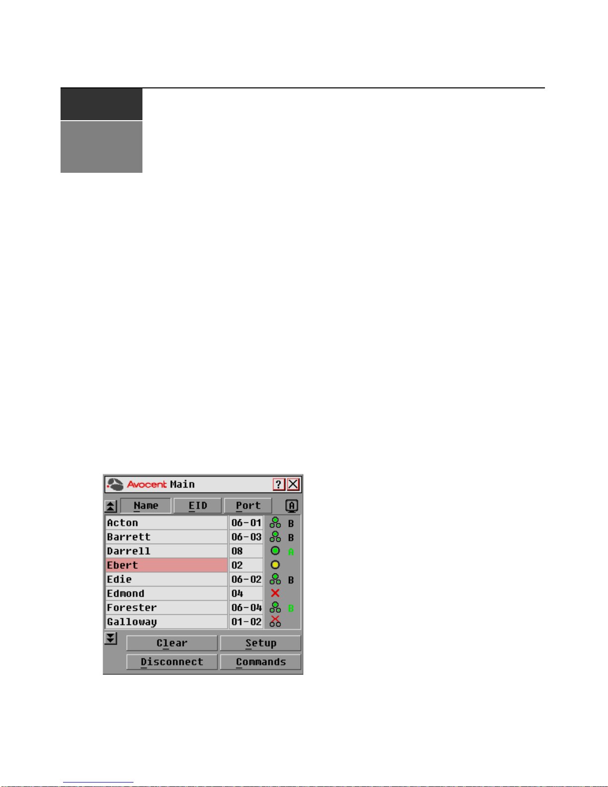
Viewing and Selecting Ports and Servers
Use the Main dialog box to view, configure and control target devices in the DSR switching
system. You may view the target devices by name, port or by the unique Electronic ID (EID)
embedded in each DSRIQ module. You will see an OSCAR interface generated port list by default
when you first launch the OSCAR interface.
The Port column indicates the port to which a target device is connected.
To access the OSCAR interface Main dialog box:
Press
Print Screen to launch the OSCAR interface. The Main dialog box will appear.
Figure 3.1: Main Dialog Box
CHAPTER
3
14 DSR Switch Installer/User Guide
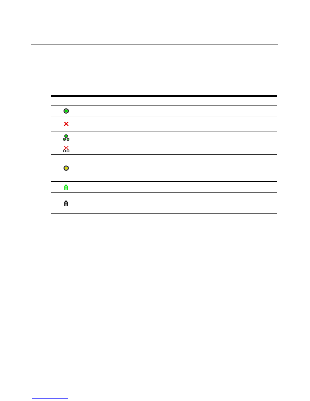
Viewing the status of your DSR switching system
The status of target devices in your system is indicated in the far right columns of the Main dialog
box. The following table describes the status symbols.
Selecting target devices
Use the Main dialog box to select target devices. When you select a target device, the DSR switch
reconfigures the keyboard and mouse to the settings for the selected target device.
To select target devices:
Double-click the target device name, EID or po rt nu mber.
-orIf the display order of your list is by port (Port button is depressed), type the port number and
press
Enter.
-orIf the display order of your list is by name or EID (Name or EID button is depressed), type the first
few letters of the name of the target device, or the EID number to establish it as unique and
press
Enter.
To select the previous target device:
Press
Print Screen and then Backspace. This key combination toggles you between the previous
and current connections.
Table 3.1: OSCAR Int e rface Status Symbols
Symbol Description
(green circle) Server connected, powered up and the DSRIQ module is online.
Connected target device is powered down or is not operating properly and the DSRIQ module
is offline.
Connected switch is online.
Connected switch is offline or not operating properly.
(yellow circle) The designated DSRIQ module is being upgraded. When this symbol displays, do
not cycle power to the DSR switch or connected target devices and do not disconnect DSRIQ
modules. Doing so may render the module permanently inoperable and require the DSRIQ
module to be returned to the factory for repair.
(green letter) DSRIQ module is being accessed by the indicated user channel.
(black letter) DSRIQ module is blocked by the indicated user channel. For instance, in Figure
3.1, user B is viewing Forester, but is blocking access to Acton, Barrett and Edie which are
connected to the same DSRIQ module.
 Loading...