

DSR Pro Series, DSR116 Owner's Manual
0099001808-00
MODEL / MODELO / MODÈLE :
DSR116
12 Volt Jump Starter with Power Converter
Arrancador portátil de 12 voltios con convertidor de energía
Démarrage de secours 12 volts avec convertisseur
OWNERS MANUAL / MANUAL DEL USUARIO / MANUEL D’UTILISATION
PLEASE SAVE THIS OWNER’S MANUAL AND READ BEFORE EACH USE.
This manual will explain how to use your jump starter safely and effectively. Please
read and follow these instructions and precautions carefully.
POR FAVOR GUARDE ESTE MANUAL DEL PROPIETARIO Y LEER ANTES DE
CADA USO. En este manual se explica cómo utilizar el arrancador con seguridad
y ecacia. Por favor, lea y siga las siguientes instrucciones y precauciones.
ESSAYER DE GARDER LE MANUEL D’INSTRUCTIONS ET LE LIRE AVANT
CHAQUE UTILISATION. Ce manuel explique comment utiliser l’unité d’une façon
sûre et efcace. S’il vous plaît lisez et suivez ces instructions et précautions.
• 2 •
1. IMPORTANT SAFETY INSTRUCTIONS
SAVE THESE INSTRUCTIONS.
WARNING – RISK OF EXPLOSIVE GASES
WORKING IN THE VICINITY OF A LEAD-ACID BATTERY IS DANGEROUS.
BATTERIES GENERATE EXPLOSIVE GASES DURING NORMAL OPERATION.
IT IS IMPORTANT THAT YOU FOLLOW THESE INSTRUCTIONS EACH TIME
YOU USE THE UNIT.
To reduce the risk of battery explosion, follow these instructions and those published by
the battery manufacturer and the manufacturer of any equipment you intend to use in the
vicinity of a battery. Review cautionary markings on these products and on the engine.
WARNING!
RISK OF ELECTRIC SHOCK OR FIRE.
1.1 Read the entire manual before using this
product. Failure to do so could result in
serious injury or death.
1.2 Keep out of reach of children.
1.3 Do not put ngers or hands into any of the
jump starter’s outlets.
1.4 Do not expose the jump starter to rain
or snow.
1.5 Use only recommended attachments. Use
of an attachment not recommended or
sold by the jump starter manufacturer may
result in a risk of re, electric shock or
injury to persons or damage to property.
1.6 To reduce the risk of damage to the
electric plug or cord, pull by the plug
rather than the cord when disconnecting
the jump starter.
1.7 To reduce the risk of electric shock, unplug
the jump starter charger from the outlet
before attempting any maintenance or
cleaning. Simply turning off the controls will
not reduce this risk.
1.8 Do not operate the jump starter with
damaged cables or clips; replace the
damaged cable or clip immediately.
1.9 Do not operate the jump starter if it has
received a sharp blow, been dropped or
otherwise damaged in any way; take it to
a qualied service person.
1.10 Do not disassemble the jump starter;
take it to a qualied service person when
service or repair is required. Incorrect
reassembly may result in a risk of re or
electric shock.
WARNING! RISK OF EXPLOSIVE GASES.
1.11 To reduce the risk of a battery explosion,
follow these instructions and those
published by the battery manufacturer and
the manufacturer of any equipment you
intend to use in the vicinity of the battery.
Review the cautionary markings on these
products and on the engine.
1.12 This jump starter employs parts, such as
switches and circuit breakers, that tend
to produce arcs and sparks. If used in a
garage, locate this jump starter 18 inches
(46 cm) or more above oor level.
CONTAINS SEALED, NON-SPILLABLE LEAD-ACID BATTERY.
MUST BE DISPOSED OF PROPERLY.
CONTIENE UNA BATERÍA SELLADA DE ÁCIDO-PLOMO NO
DERRAMABLE QUE DEBE DESECHARSE APROPIADAMENTE.
CONTIENT UNE BATTERIE À L’ACIDE QUI DOIT ÊTREDISPOSÉ
CORRECTEMENT.
WARNING: Possible explosion hazard. Contact with battery acid may cause severe burns
and blindness. Keep out of reach of children.
ADVERTENCIA: Posible riesgo de una explosión. El contacto con una batería de ácido
puede causar quemaduras y ceguera. Manténgase alejado de los niños.
AVERTISSEMENT : Hasard d’explosion possible. Contact avec l’acide de batterie peut
provoquer sévère brûle et la cécité. Ne le laissez pas a la portée des enfants.

• 3 •
2. PERSONAL PRECAUTIONS
WARNING! RISK OF EXPLOSIVE
GASES. A SPARK NEAR THE BATTERY
MAY CAUSE A BATTERY EXPLOSION.
TO REDUCE THE RISK OF A SPARK
NEAR THE BATTERY:
2.1 NEVER smoke or allow a spark or ame
in the vicinity of a battery or engine.
2.2 Do not permit the internal battery of the
jump starter to freeze. Never charge a
frozen battery.
2.3 To prevent sparking, NEVER allow clips to
touch together or contact the same piece
of metal.
2.4 When charging the internal battery, work
in a well ventilated area and do not restrict
the ventilation in any way.
2.5 Be sure the area around the battery is
well ventilated while the jump starter is
being used.
2.6 Remove personal metal items such as
rings, bracelets, necklaces and watches
when working with a lead-acid battery. A
lead-acid battery can produce a shortcircuit current high enough to weld a ring
or the like to metal, causing a severe burn.
2.7 Be extra cautious, to reduce the risk of
dropping a metal tool onto the battery. It
might spark or short-circuit the battery or
other electrical part that may cause an
explosion.
2.8 Consider having someone nearby to
come to your aid when you work near a
lead-acid battery.
2.9 Have plenty of fresh water and soap
nearby in case battery acid contacts your
skin, clothing or eyes.
2.10 Wear complete eye and body protection,
including safety goggles, face shield and
protective clothing. Avoid touching your
eyes while working near the battery.
2.11 If battery acid contacts your skin or
clothing, immediately wash the area
with soap and water. If acid enters your
eye, immediately ood the eye with cold
running water for at least 10 minutes and
get medical attention right away.
2.12 If battery acid is accidentally swallowed,
drink milk, the whites of eggs or water.
DO NOT induce vomiting. Seek medical
attention immediately.
WARNING! RISK OF CONTACT WITH
BATTERY ACID. BATTERY ACID IS A
HIGHLY CORROSIVE SULFURIC ACID.
2.13 Clean the battery terminals before using
the jump starter. During cleaning, keep
airborne corrosion from coming into
contact with your eyes, nose and mouth.
Use baking soda and water to neutralize
the battery acid and help eliminate
airborne corrosion. Do not touch your
eyes, nose or mouth.
2.14 Add distilled water to each cell until the
battery acid reaches the level specied
by the battery manufacturer. Do not
overll. For a battery without removable
cell caps, such as valve regulated lead
acid batteries (VRLA), carefully follow the
manufacturer’s instructions.
2.15 Read, understand and follow all
instructions for the jump starter, battery,
vehicle and any equipment used near the
battery and jump starter.
2.16 Determine the voltage of the battery by
referring to the vehicle owner’s manual
and make sure that the output voltage of
the jump starter is correct.
2.17 Make sure that the jump starter cable
clips make tight connections.
2.18 WARNING: This product contains one
or more chemicals known to the State
of California to cause cancer and birth
defects or other reproductive harm.
2.19 Restrictions on Use:
The converter may not be used with life
support devices or systems. Failure of this
converter can reasonably be expected to
cause failure of that life support device
or system, or to affect the safety or
effectiveness of that device or system.
3. CONNECTING THE JUMP STARTER
WARNING! A SPARK NEAR THE
BATTERY MAY CAUSE A BATTERY
EXPLOSION. TO REDUCE THE RISK
OF A SPARK NEAR THE BATTERY:
3.1 Attach the output cables to the battery
and chassis as indicated below. Never
allow the output clips to touch each other.
3.2 Position the DC cables to reduce the risk of
damage by the hood, door and moving or
hot engine parts. NOTE: If it is necessary
to close the hood during the jump starting
process, ensure that the hood does not
touch the metal part of the battery clips or
cut the insulation of the cables.
3.3 Stay clear of fan blades, belts, pulleys
and other parts that can cause injury.
3.4 Check the polarity of the battery posts.
The POSITIVE (POS, P, +) battery post
usually has a larger diameter than the
NEGATIVE (NEG, N, -) post.
3.5 Determine which post of the battery is
grounded (connected) to the chassis.
• 4 •
If the negative post is grounded to the
chassis (as in most vehicles), see step
3.6. If the positive post is grounded to the
chassis, see step 3.7.
3.6 For a negative-grounded vehicle, connect
the POSITIVE (RED) clip from the jump
starter to the POSITIVE (POS, P, +)
ungrounded post of the battery. Connect
the NEGATIVE (BLACK) clip to the
vehicle chassis or engine block away from
the battery. Do not connect the clip to the
carburetor, fuel lines or sheet-metal body
parts. Connect to a heavy gauge metal
part of the frame or engine block.
3.7 For a positive-grounded vehicle, connect
the NEGATIVE (BLACK) clip from the
jump starter to the NEGATIVE (NEG, N, -)
ungrounded post of the battery. Connect
the POSITIVE (RED) clip to the vehicle
chassis or engine block away from the
battery. Do not connect the clip to the
carburetor, fuel lines or sheet-metal body
parts. Connect to a heavy gauge metal
part of the frame or engine block.
3.8 When disconnecting the jump starter, turn
all switches to off (if applicable), remove
the clip from the vehicle chassis, then
remove the clip from the battery terminal.
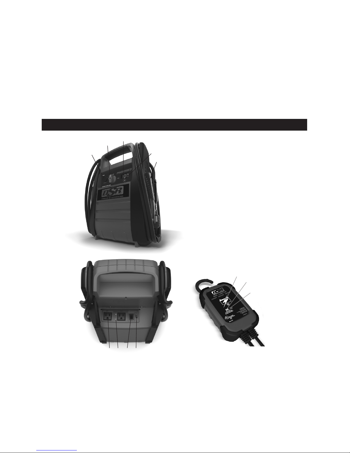
4. FEATURES
1
2
3
Jump Starter
1. 12 Volt DC power outlet
2. Jump starter ON/OFF switch
3. Multi-function digital display
4. Display button
5. Heavy-duty battery clamps
6. (2) AC outlets
7. Converter status LEDs
8. Converter/USB ON/OFF switch
9. USB port
Charger
1. Charging status LED
2. Bad Battery LED
3. Power LED
1
2
3
4
5
6 7 8 9
4.1 Digital Display
When connected to a battery, the digital
display can be used to indicate the battery’s
voltage. When not connected to a battery,
the digital display can be used to indicate
the percent of charge or the voltage of the
jump starter’s internal battery.
To check the internal battery’s charge
status, make sure the rotary switch is in
the OFF position, then press the display
button on the front of the jump starter.
The digital display will show the battery’s
percent of charge. A fully charged battery
will read 100%. Charge the internal battery
if the display shows it is under 100%.
NOTE: The internal battery’s percent of
charge is most accurate when the jump
starter has been disconnected from all
devices and charging sources for a few
hours.

• 5 •
To check the voltage level of the jump
starter’s internal battery, make sure the clips
are attached to their plastic storage holders
and not touching each other, and then turn
the rotary switch to the 12V position. The
display will indicate the battery’s voltage.
To check the voltage level of the vehicle’s
battery, make sure the switch in the OFF
position, then connect the clips to the
vehicle’s battery. The display will indicate
the battery’s voltage.
4.2 Charger LED Indicators
POWER (green) LED lit: The
charger is connected to AC power.
CHARGING STATUS LED (green)
pulsing slowly: The charger is
charging the jump starter’s internal
battery, or the battery is fully
charged and the charger is in
Maintain mode.
CHARGING STATUS LED
(yellow/orange) ashing rapidly:
The charger has detected a problem
with the battery. See Troubleshooting
for more information.
BAD BATTERY (red) LED lit:
The charger has detected a problem
with the battery. See Troubleshooting
for more information.
5. CHARGING THE INTERNAL BATTERY OF THE JUMP STARTER
IMPORTANT!
CHARGE IMMEDIATELY AFTER
PURCHASE, AFTER EACH USE AND
EVERY 30 DAYS, TO KEEP THE UNIT’S
INTERNAL BATTERY FULLY CHARGED
AND PROLONG BATTERY LIFE.
To check the internal battery’s charge
status, make sure the rotary switch is in the
OFF position, then press the display button
on the front of the jump starter. The digital
display will show the battery’s percent of
charge. A fully charged battery will read
100%. Charge the internal battery if the
display shows it is under 100%. Complete
charging may take up to 48 hours.
5.1 Grounding and AC Power Cord
Connections
IMPORTANT: Only use the charger that
was included with the jump starter to charge
the internal battery of the jump starter.
Using a different charger could result in
personal injury or property damage.
WARNING!
RISK OF ELECTRIC SHOCK OR FIRE.
This battery charger is for use on a
nominal 120V circuit. The plug must be
plugged into an outlet that is properly
installed in accordance with all local
codes and ordinances. The plug pins
must t the receptacle (outlet). Do not use
with an ungrounded system.
DANGER. Never alter the AC cord or plug
provided – if it does not t the outlet, have
a proper outlet installed by a qualied
electrician. An improper connection can
result in a risk of an electric shock or
electrocution.
An extension cord should not be used
unless absolutely necessary. Use of an
improper extension cord could result
in a risk of re and electric shock. If an
extension cord must be used, make sure:
• That the pins on the plug of the extension
cord are the same number, size and
shape as those of the plug on the charger.
• That the extension cord is properly wired
and in good electrical condition.
• That the wire size is large enough for the
AC ampere rating of the charger,
as specied:
Length of cord (feet) 25 50 100 150
AWG* size of cord 18 18 18 16
*AWG-American Wire Gauge
5.2 Charging the Jump Starter
with included Charger
1. Make sure the charger and jump starter
are placed on a dry, nonammable
surface. To charge the jump starter, plug
the charger into the charging port on the
front of the jump starter.
2. Conrm the AC outlet voltage matches
the input voltage of the charger.
3. Connect the charger to the AC wall
outlet and conrm that the green
POWER LED on the charger turns on.
4. Check that the green CHARGING
STATUS LED on the charger is pulsing
slowly, to indicate that charge process
has started. To see the status of the
charge, check the percentage shown
on the jump starter display.
5. When the jump starter display shows
100 (%), the internal battery is fully
charged and the jump starter is ready
to use. Complete charging may take up
to 24 hours.
NOTE: The green CHARGING

• 6 •
STATUS LED will remain pulsing after
the display shows 100%, as the charger
automatically goes into Maintain mode
and maintains the battery at full charge
without damaging it.
6. After the charge is complete, disconnect
the charger from the AC outlet, then
disconnect the charger from jump starter.
5.3 Charger Modes
Automatic charging mode
When an automatic charge is performed,
the charger switches to maintain mode
automatically after the battery is charged.
Aborted Charge
If charging cannot be completed normally,
charging will abort. When charging aborts,
the charger’s output is shut off. The BAD
BATTERY (red) LED will light. Do
not continue attempting to charge the
battery. Check the battery and replace, if
necessary.
Desulfation Mode
Desulfation could take 8 to 10 hours. If
desulfation fails, charging will abort. The
red BAD BATTERY LED will light and
the yellow/orange CHARGING STATUS
LED will ash.
Completion of Charge
When the internal battery is fully charged,
the jump starter’s display will show “100”.
Maintain Mode (Float Mode Monitoring)
When the internal battery is fully charged
and the jump starter display shows “100”,
the charger has started maintain mode. In
this mode, the charger keeps the battery
fully charged by delivering a small current
when necessary. If the charger has to
provide its maximum maintain current for
a continuous 12 hour period, it will go into
abort mode (see Aborted Charge). This
is usually an indication of a bad battery;
have the jump starter checked.
5.4 Charging the Internal Battery
While Driving
You may also charge the internal battery
while driving, using a male-to-male charger
cable (part number 94500109 – sold
separately).
IMPORTANT: DO NOT CHARGE THE
INTERNAL BATTERY FOR MORE THAN
30 MINUTES OR LEAVE THE BATTERY
UNATTENDED. IT COULD EXPLODE,
CAUSING PROPERTY DAMAGE OR
PERSONAL INJURY.
1. Make sure the car is running.
2. Insert one end of the accessory cable
into the 12V DC power outlet.
3. Insert the other end of the accessory
cable into the vehicle’s accessory
outlet (lighter socket).
NOTE: Using this method to charge the
battery overrides the maintain mode and
the battery can be overcharged.
4. Monitor the progress of the charge by
pressing the Percentage of Charge
button on the front of the unit. Do not
leave the battery unattended or it could
explode, causing property damage and
personal injury. When the battery is fully
charged, disconnect the accessory cable
from the jump starter, and then from the
lighter socket of the vehicle.
NOTE: Completely disconnect the charger
cable when the engine is not running.
6. OPERATING INSTRUCTIONS
6.1 Jump Starting a Vehicle Engine
IMPORTANT: Using the jump starter
without a battery installed in the vehicle will
damage the vehicle’s electrical system.
IMPORTANT: Do not use the jump starter
while charging its internal battery.
1. Turn the vehicle’s ignition OFF before
making cable connections.
2. Make sure the rotary switch on the
front of the jump starter is in the OFF
position. Connect the jump starter to
the battery, following the precautions
listed in section 3.
WARNING! RISK OF EXPLOSION.
If you have connected the clips backward,
an audio alarm will sound. DO NOT turn
the rotary switch to the 12V position.
This could cause serious damage to the
jump starter or the vehicle. Reverse the
connections and the audio alarm will stop.
3. If no audio alarm sounds, turn the
rotary switch to the 12V position. The
clips are now powered.
4. Crank the engine. If the engine does not
start within 3-8 seconds, stop cranking
and wait at least 1 minute before
attempting to start the vehicle again.
(This permits the battery to cool down.)
5. After the engine starts, turn the rotary
switch to the OFF position. Disconnect
the black clip (-), then the red clip (+) in
that order, and clip them back onto the
jump starter storage holders.
6. Recharge the jump starter as soon as
possible after use.
NOTE: If the cables are connected to a
24 volt system when the switch is in the
12 volt position, the audio alarm will
sound continuously. TURN OFF the jump
starter immediately or internal battery
damage could occur.

• 7 •
WARNING! RISK OF EXPLOSION.
To prevent sparking, NEVER allow the
clips to touch together or to contact the
same piece of metal. Never attempt to
jump start a frozen battery.
6.2 Powering A 12V DC Device:
The jump starter is a power source for all
12V DC accessories that are equipped
with a 12V accessory plug. Use it for
power outages and shing or camping
trips. Estimated usage time is listed in the
following chart.
1. Make sure the device to be powered
is OFF before inserting a 12V DC
accessory plug into the 12V DC socket.
2. Ensure the battery clips are securely
clipped on the storage holders.
3. Open the protective cover of the 12V DC
power outlet on the front of the jump
starter.
4. Plug the 12V DC device into the 12V
DC power outlet, and turn the 12V DC
device on (if required).
5. If the 12V DC device draws more than
15A or has a short circuit, the internal
circuit breaker of the jump starter
will trip and disconnect the power to
the device. Disconnect the 12V DC
device. The breaker will automatically
reset a short time after an overload is
disconnected.
6. Recharge immediately after unplugging
the 12V DC device.
NOTE: The DC power outlet is wired
directly to the internal battery. Extended
operation of a 12V DC device may result
in excessive battery drain.
12V DC ESTIMATED RUN-TIMES
APPLIANCE
TYPE
ESTIMATED
WATTAGE
ESTIMATED
RUN TIME
Cell phone,
uorescent light
4 watts 66 hrs
Radio, fan,
depth nder
9 watts 23.9 hrs
Camcorder 15 watts 17.6 hrs
Electrical tool 24 watts 11 hrs
Electric cooler 48 watts 5.5 hrs
Car vacuum,
air compressor
80 watts 3.3 hrs
NOTE: Actual time may vary. Times are based
on a fully charged internal battery.
6.3 Using the USB Port
The USB port provides up to 2.1A at 5V DC.
1. Ensure the battery clips are securely
clipped on the storage holders.
2. Turn the Rear Console USB/Converter
switch to the “USB” position.
3. Plug the device into the USB port on
the rear console.
4. Turn the USB device on.
5. Reverse these steps when nished
using the USB port.
6. Charge the jump starter as soon as
possible after using the USB port.
6.4 Before Using the Converter
Important Safety Instructions:
1. Keep the jump starter well ventilated
in order to properly disperse heat
generated while it is in use. Make sure
there are several inches of clearance
around the top and sides and do not
block the vents on the sides of the
jump starter.
2. Make sure the jump starter is not close
to any potential source of ammable
fumes or clothing.
3. Keep the jump starter dry.
4. DO NOT allow the jump starter to
come into contact with rain or moisture.
5. DO NOT operate the jump starter if
you, the jump starter, the device being
operated or any other surfaces that
may come in contact with any power
source are wet. Water and many other
liquids can conduct electricity, which
may lead to serious injury or death.
6. Do not place the jump starter on or
near heating vents, radiators or other
sources of heat.
7. Do not place the jump starter in direct
sunlight. The ideal air temperature for
operation is between 50° and 80°F.
8. Do not use the converter near an open
engine compartment where fumes may
accumulate.
9. Do not modify the AC receptacles in
any way.
6.5 Using the Converter
It is important to know the continuous
wattage of the device you plan to use with
the converter. The jump starter must be
used with devices drawing 400 watts or
less. If the wattage is not marked on the
device, use only devices that draw less than
4.0 Amps of AC current.
Devices like TVs, fans or electric motors
require additional power to start (commonly
known as the “starting” or “peak” power).
The jump starter can supply a momentary
surge in wattage; however, even devices
rated less than the maximum 400 watts can
exceed the converter’s surge capability and
cause an automatic overload shutdown.
Do not use the converter with a product
that draws a higher wattage than the
converter can provide, as this may cause
damage to the converter and the product.
Make sure the device you are using is
compatible with a modied sine wave
converter.
• 8 •
CAUTION: Always run a test to establish
whether the converter will operate a
particular piece of equipment or device.
In the event of a power overload, the
converter is designed to automatically
shut down. This safety feature prevents
damaging the converter while testing
devices and equipment with the 400-watt
range.
If powering more than one device, start
one device at a time to avoid a power
surge and/or converter overload. The
surge load of each device should not
exceed the converter’s continuous
operation wattage rate.
IMPORTANT: If you are using the power
converter to operate a battery charger,
monitor the temperature of the battery
charger for about 10 minutes. If the
battery charger becomes abnormally
warm, disconnect it from the converter
immediately.
NOTE: You can use an extension cord
from the converter to the device without
signi cantly decreasing the power being
generated by the converter. For best
operating results, the extension cord should
be no longer than 50 feet (15.24 meters).
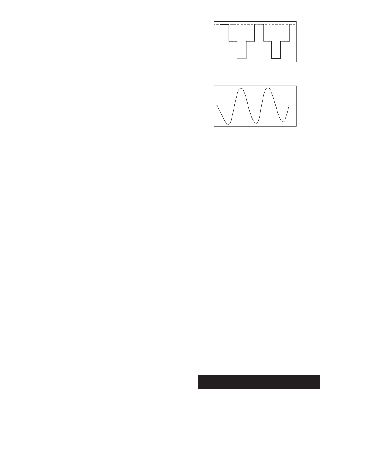
IMPORTANT: This converter uses a
modi ed sine waveform (diagram A)
which is not quite the same as power
company electricity (diagram B). For the
following devices, we strongly recommend
that you use caution and check the
device’s manual to make sure it is
compatible with modi ed sine waveform.
1. Switch mode power supplies
2. Linear power supplies
3. Class 2 transformers
4. Line lter capacitors
5. Shaded pole motors
6. Fan motors
7. Microwave ovens
8. Fluorescent and high intensity lamps
(with a ballast)
9. Transformerless battery chargers
Using the converter with any of these
devices may cause the device to run
warmer or overheat.
Modifi ed sine waveform
produced by converter
Diagram A
Diagram B
Pure sine waveform
typical of home AC outlet
6.6 Powering a 110V AC Device
1. Ensure the battery clips are securely
on the storage holders.
2. Make sure the 110V AC device to be
operated is turned OFF.
3. Plug the 110V AC device into the AC
power outlet on the back of the jump
starter and place the converter switch in
the “120V” position. The GREEN LED
will light, indicating the converter is on.
4. Turn the device on.
5. If the device does not operate properly
when rst connected to the converter,
push the converter rocker switch ON,
OFF, and ON again in quick succession.
If this procedure is not successful, it is
likely that the converter does not have
the required capacity to operate the
device intended.
6. To disconnect: Turn off the device,
place the converter switch in the “O”
(OFF) position, then unplug the device
from the 110V AC power outlet.
7. Charge the jump starter as soon as
possible after each use.
WARNING: RISK OF ELECTRIC SHOCK.
Incorrect operation of your converter may
result in damage and personal injury.
The converter output is 110V AC and can
shock or electrocute the same as any
ordinary household AC wall outlet.
110V AC ELECTRICAL DEVICE RUN-TIMES
APPLIANCE TYPE
ESTIMATED
WATTAGE
ESTIMATED
RUN TIME
Spotlights, sump
pumps, DVD players
100 watts 1.5 hrs
Faxes, TVs,
small power tools
150 watts 1.25 hrs
Computer printer,
medium power tools,
blenders
200 watts 55 min.
NOTE: These are estimated run-times, actual time
may vary. Times are based on the internal battery
being new, fully charged and operated at room
temperature.

• 9 •
NOTE: The maximum continuous load is
400 watts. Do not use the inverter with a
product that draws more than 400 watts,
as this may cause damage to the inverter
and the product.
6.7 Converter Shutdown Protection
The GREEN LED lights automatically
when the converter is turned on. The RED
LED will light and the coinverter will shut
down under the following conditions:
1. When the power input from the jump
starter’s battery drops to approximately
10.5 volts, low battery shutdown
occurs and the inverter shuts off.
NOTE: At approximately 10.5 volts, the
inverter alarm will sound, indicating the
battery voltage is getting low. Solution:
Recharge the jump starter.
2. When the power input from the jump
starter’s battery exceeds 15 volts, high
voltage overload protection occurs.
Solution: Reduce the voltage range of the
battery to between 12 volts and 14 volts.
3. The continuous load demand from the
equipment or device being operated
exceeds the inverter’s 400 watt capacity.
Solution: Use a lower rated device.
4. The case temperature becomes hot
(exceeds 145°F). Solution: Allow the
inverter to cool. Do not block the cooling
slots or air ow over and through the
jump starter. Reduce the load on the
converter to the continuous rated output.
RESET: To reset after shutdown occurs,
turn the converter OFF. Check the source of
the problem and correct. Turn the converter
back ON.
7. MAINTENANCE INSTRUCTIONS
7.1 After use and before performing
maintenance, unplug and disconnect
the jump starter.
7.2 Use a dry cloth to wipe all battery corrosion
and other dirt or oil from the battery clips,
cords and the jump starter case.
7.3 Ensure that all of the jump starter
components are in place and in good
working condition.
7.4 All servicing should be performed by
qualied service personnel.
8. MOVING AND STORAGE INSTRUCTIONS
8.1 Store inside, in a cool, dry place.
8.2 Do not store the clips on the handle,
clipped together, on or around metal, or
clipped to cables. The clips on the jump
starter are live when the switch is in the
ON position and will produce arcing or
sparking if they come in contact with each
other. To prevent accidental arcing, always
place the switch in the OFF position and
keep the clips on the storage holders when
not using it to jump start a vehicle.
8.3 If the jump starter is moved around the
shop or transported to another location,
take care to avoid/prevent damage to the
cords, clips and jump starter. Failure to
do so could result in personal injury or
property damage.
IMPORTANT: Do not use and/or store the
jump starter in or on any area or surface
where damage could occur if the internal
battery should unexpectedly leak acid.
8.4 IMPORTANT:
• CHARGE IMMEDIATELY AFTER
PURCHASE
• KEEP FULLY CHARGED
Charge the jump starter’s internal battery
immediately after purchase, after every
use and every 30 days.
All batteries are affected by temperature.
The ideal storage temperature is at
70°F. The internal battery will gradually
self-discharge (lose power) over time,
especially in warm environments. Leaving
the battery in a discharged state may
result in permanent battery damage. To
ensure satisfactory performance and
avoid permanent damage, charge the
internal battery every month.

• 10 •
9. TROUBLESHOOTING
Jump Starter
PROBLEM POSSIBLE CAUSE SOLUTION
The jump starter won’t
jump start my car.
Clamps are not making a good
connection to the battery.
The jump starter’s battery is not
charged.
The vehicle’s battery is defective.
Check for poor connection to
battery and frame. Make sure
connection points are clean.
Check the battery charge status
by pressing the Display button
on the front of the unit. The display
will show the percentage of
charge.
Have the battery checked.
The jump starter won’t
power my 12V device.
The 12V device is not
turned on.
The battery inside the jump
starter is not properly charged
(is under 10.5V).
The 12V device draws more
than 15A or has a short circuit.
Turn on the 12V device.
Check the battery charge status
by pressing the Display button on
the front of the unit. The display
will show the percentage of
charge.
Disconnect the 12V device. The
internal breaker will automatically
reset after a minute or two. Try
using the 12V device again.
The battery in the jump
starter won’t hold a
charge.
The battery is bad (will not
accept a charge).
Replace the battery.
The jump starter’s alarm
is on.
Connections are reversed. Disconnect the jump starter and
reverse the clamps.
The jump starter won’t
power my 110V AC
device.
The converter is not turned on.
The 110V AC device is not
turned on.
The battery inside the jump
starter is not properly charged
(is under 10.5V).
The 110V AC device draws
more than 400 watts or has a
short circuit.
Turn on the converter.
Turn on the 110V AC device.
Check the battery charge status
by pressing the button on the
front of the jump starter. See the
Digital Display section of this
manual.
Disconnect the 110V AC device.
The converter will reset after a
second or two. Try the 110V AC
device again. If it happens again,
use a smaller device.
The RED LED near the
converter ON/OFF switch
is on and the converter
will not function.
Converter has gone into
shutdown mode.
See the Converter Shutdown
Protection section.
Charger
PROBLEM REASON SOLUTION
The green POWER
LED does not light when
charger is properly
connected.
AC outlet is dead.
Poor electrical connection.
Check for open fuse or circuit
breaker supplying AC outlet.
Check power cord and extension
cord for a loose tting plug.

• 11 •
PROBLEM REASON SOLUTION
The red BAD
BATTERY LED is lit.
The battery is sulfated.
Lack of progress is detected and
battery voltage is below 14.2V.
The battery’s initial voltage is
below 12.2V and the total input
is less than 1.5 Ah.
The battery voltage drops
below 12.2V during Maintain
Mode.
The charger is in desulfation
mode. Continue charging for
several hours. If not successful,
have the battery checked.
The battery may be overheated. If
so, allow the battery to cool. The
battery may be too large or have a
short circuit. Have battery checked
or replaced.
The battery capacity is too low,
or the battery is too old. Have it
checked or replaced.
The battery won’t hold a charge.
May be caused by a drain on
the battery or the battery could
be bad. Make sure there are no
loads on the battery. If there are
remove them. If there are none,
have the battery checked or
replaced.
The red BAD
BATTERY LED is lit and
the yellow/orange
CHARGING STATUS
LED is ashing rapidly.
The battery voltage is still below
10V after 2 hours of charging.
(or)
In maintain mode, the output
current is more than 1.5A for 12
hours.
Desulfation was unsuccessful.
The battery may be defective.
Make sure there are no loads on
the battery. If there are, remove
them. If there are none, have the
battery checked or replaced.
The battery may be defective.
Have battery checked or replaced.
10. BEFORE RETURNING FOR REPAIRS
If these solutions do not eliminate the problem, or for more information
about troubleshooting, contact customer service for assistance:
services@schumacherelectric.com
www.batterychargers.com
or call 1-800-621-5485, Monday-Friday 7:00am to 5:00pm CST
For REPAIR OR RETURN, contact Customer Service at 1-800-621-5485.
DO NOT SHIP UNIT until you receive a RETURN MERCHANDISE AUTHORIZATION
(RMA) number from Customer Service at Schumacher Electric Corporation.
11. SPECIFICATIONS
Jump Starter
Internal Battery Type .....................................Sealed, Maintenance Free, AGM, Lead-Acid
Nominal Voltage ......................................................................................................12V DC
Capacity ......................................................................................................................22Ah
DC Power Output (Maximum Continuous Load)...........................................................15A
Peak Amps .................................................................................................................. 2250
Cranking Amps.............................................................................................................. 525
Cold Cranking Amps ..................................................................................................... 350
Battery Hookup Cables .................................................................. 4 AWG, 60" (152.4 cm)
Dimensions (H x W x D)..................................... 16.3˝ x 12.9˝ x 7.9˝ (41.4 x 32.7 x 20 cm)
Weight ....................................................................................................25.5 lbs (11.56 kg)

• 12 •
AC Power Specications
Maximum continuous power ............................................................................... 400 Watts
Surge capability (peak power) ............................................................................ 800 Watts
No load current draw.......................................................................................... <0.3 Amps
Output waveform...................................................................................Modied sine wave
Input voltage range ................................................................................... 10.5V-15.5V DC
AC outlet ...........................................................................Two, 110V AC NEMA 5-15 USA
Charger
Input voltage ..................................................................................120V AC @ 60Hz, 0.5A
Output voltage.........................................................................................................12V DC
Output current rating .......................................................................................................2A
12. REPLACEMENT PARTS/ACCESSORIES
Male-to-male accessory cable ............................................................................ 94500109
DSR2 Charger ..............................................................................................2299003063Z
Replacement battery ..................................................................................... 5799000010Z
13. LIMITED WARRANTY
SCHUMACHER ELECTRIC CORPORATION, 801 BUSINESS CENTER DRIVE, MOUNT
PROSPECT, IL 60056-2179, MAKES THIS LIMITED WARRANTY TO THE ORIGINAL
RETAIL PURCHASER OF THIS PRODUCT. THIS LIMITED WARRANTY IS NOT
TRANSFERABLE OR ASSIGNABLE.
Schumacher Electric Corporation (the “Manufacturer”) warrants this jump starter for one
(1) year from the date of purchase at retail against defective material or workmanship that
may occur under normal use and care. If your unit is not free from defective material or
workmanship, Manufacturer’s obligation under this warranty is solely to repair or replace
your product, with a new or reconditioned unit, at the option of the Manufacturer. It is the
obligation of the purchaser to forward the unit, along with proof of purchase and mailing
charges prepaid to the Manufacturer or its authorized representatives in order for repair
or replacement to occur.
Manufacturer does not provide any warranty for any accessories used with this product
that are not manufactured by Schumacher Electric Corporation and approved for use
with this product. This Limited Warranty is void if the product is misused, subjected to
careless handling, repaired, or modied by anyone other than Manufacturer or if this unit
is resold through an unauthorized retailer. Manufacturer may void this Limited Warranty if
a “warranty void if removed” label is removed from the product.
Manufacturer makes no other warranties, including, but not limited to, express, implied or
statutory warranties, including without limitation, any implied warranty of merchantability or
implied warranty of tness for a particular purpose. Further, Manufacturer shall not be liable
for any incidental, special or consequential damage claims incurred by purchasers, users
or others associated with this product, including, but not limited to, lost prots, revenues,
anticipated sales, business opportunities, goodwill, business interruption and any other injury
or damage. Any and all such warranties, other than the limited warranty included herein,
are hereby expressly disclaimed and excluded. Some states do not allow the exclusion or
limitation of incidental or consequential damages or length of implied warranty, so the above
limitations or exclusions may not apply to you. This warranty gives you specic legal rights
and it is possible you may have other rights which vary from this warranty.
THIS LIMITED WARRANTY IS THE ONLY EXPRESS LIMITED WARRANTY AND THE
MANUFACTURER NEITHER ASSUMES OR AUTHORIZES ANYONE TO ASSUME OR
MAKE ANY OTHER OBLIGATION TOWARDS THE PRODUCT OTHER THAN THIS
WARRANTY.
Schumacher® and the Schumacher logo are registered trademarks
of Schumacher Electric Corporation.
 Loading...