

DSR DSR100 Owner's Manual
0099001647-02
Model / Modelo / Modèle :
DSR100
Booster
Arrancador
Aide au démarrage
PLEASE SAVE THIS OWNER’S MANUAL AND READ BEFORE EACH USE.
This manual will explain how to use the booster and charger safely and effectively.
Please read and follow these instructions and precautions carefully.
POR FAVOR GUARDE ESTE MANUAL DEL PROPIETARIO Y LEER ANTES DE
CADA USO. En este manual se explica cómo utilizar el arrancador y cargador con
seguridad y ecacia. Por favor, lea y siga las siguientes instrucciones y precauciones.
VEILLEZ A CONSERVER CES INSTRUCTIONS ET LES LIRE AVANT CHAQUE
UTILISATION. Ce guide vous montrera comment utiliser le booster efcacement
et en toute sécurité. Veuillez lire et suivre ces instructions et précautions.
OWNERS MANUAL
MANUAL DEL USUARIO
MANUEL D’UTILISATION
CONTENTS
IMPORTANT SAFETY INSTRUCTIONS ............................................................................... 5
PERSONAL SAFETY PRECAUTIONS ..................................................................................5
PREPARING TO USE THE BOOSTER .................................................................................. 6
BOOSTER LOCATION ........................................................................................................... 6
INSTALLATION INSTRUCTIONS ........................................................................................... 6
FEATURES ............................................................................................................................. 6
CHARGING THE INTERNAL BATTERY OF THE BOOSTER ................................................ 7
OPERATING INSTRUCTIONS ............................................................................................... 8
MAINTENANCE INSTRUCTIONS.......................................................................................... 9
MOVING AND STORAGE INSTRUCTIONS .......................................................................... 9
SPECIFICATIONS ................................................................................................................ 10
REPLACEMENT PARTS ...................................................................................................... 10
TROUBLESHOOTING.......................................................................................................... 10
BEFORE RETURNING FOR REPAIRS ............................................................................... 12
LIMITED WARRANTY .......................................................................................................... 12
WARRANTY CARD .............................................................................................................. 31
CONTAINS SEALED NON-SPILLABLE LEAD-ACID BATTERY.
MUST BE DISPOSED OF PROPERLY.
CONTIENE UNA BATERÍA SELLADA DE ÁCIDO-PLOMO NO
DERRAMABLE QUE DEBE DESECHARSE APROPIADAMENTE.
CONTIENT UNE BATTERIE À L’ACIDE QUI DOIT ÊTRE
MANIPULEE CORRECTEMENT.
WARNING: Possible explosion hazard. Contact with battery acid may cause
severe burns and blindness. Keep out of reach of children.
ADVERTENCIA: Posible riesgo de una explosión. El contacto con una batería de
ácido puede causar quemaduras y ceguera. Manténgase alejado de los niños.
AVERTISSEMENT : Risque d’explosion possible. Entrer en contact avec l'acide de
batterie peut provoquer de sévères brûlures et la cécité. Tenir hors de portée des enfants.

CONTENIDOS
INSTRUCCIONES DE SEGURIDAD IMPORTANTES ......................................................... 13
PRECAUCIONES DE SEGURIDAD PERSONAL ................................................................ 13
PREPARACIÓN PARA UTILIZAR EL ARRANCADOR ......................................................... 14
UBICACIÓN DEL ARRANCADOR ....................................................................................... 14
INSTRUCCIONES PARA LA INSTALACIÓN ........................................................................ 14
CARACTERÍSTICAS ............................................................................................................ 14
CARGA DE LA BATERÍA INTERNA DEL ARRANCADOR ................................................... 15
INSTRUCCIONES DE OPERACIÓN ................................................................................... 16
INSTRUCCIONES DE MANTENIMIENTO ........................................................................... 17
INSTRUCCIONES PARA EL MANEJO Y ALMACENAMIENTO........................................... 18
ESPECIFICACIONES........................................................................................................... 18
REPUESTOS ........................................................................................................................ 18
LOCALIZACIÓN Y SOLUCIÓN DE PROBLEMAS ............................................................... 19
ANTES DE DEVOLVER A REPARACIONES ....................................................................... 20
GARANTÍA LIMITADA .......................................................................................................... 21
TARJETA DE GARANTÍA ..................................................................................................... 31

TABLE DES MATIÈRES
CONSIGNES DE SÉCURITÉ IMPORTANTES ................................................................... 22
MESURES DE SÉCURITÉ PERSONNELLES ..................................................................... 22
PRÉPARATION À L’UTILISATION DU BOOSTER ............................................................... 23
EMPLACEMENT DU BOOSTER .......................................................................................... 23
INSTRUCTIONS POUR L’INSTALLATION ...........................................................................23
CARACTÉRISTIQUES ......................................................................................................... 23
CHARGE DE LA BATTERIE INTERNE DU BOOSTER ....................................................... 24
CONSIGNES D’UTILISATION .............................................................................................. 25
INSTRUCTIONS D’ENTRETIEN .......................................................................................... 26
INSTRUCTIONS DE STOCKAGE ET EMPLACEMENT ...................................................... 27
SPÉCIFICATIONS ................................................................................................................ 27
PIÊCES DE RECHANGE ..................................................................................................... 27
DÉPANNAGE ....................................................................................................................... 28
AVANT DE RETOURNER POUR LES RÉPARATIONS ....................................................... 29
GARANTIE LIMITÉE ............................................................................................................ 30
CARTE DE GARANTIE ........................................................................................................ 32

• 5 •
1. IMPORTANT SAFETY INSTRUCTIONS
SAVE THESE INSTRUCTIONS.
1.1 SAVE THESE INSTRUCTIONS –
This manual contains important safety
and operating instructions.
WARNING!
RISK OF ELECTRIC SHOCK OR FIRE.
1.2 Read the entire manual before using this
product. Failure to do so could result in
serious injury or death.
1.3 This booster is not intended for use by
persons (including children) with reduced
physical, sensory or mental capabilities,
or lack of experience and knowledge,
unless they have been given supervision or
instruction concerning the use of the booster
by a person responsible for their safety.
1.4 Children should be supervised, to ensure
they do not play with the booster or charger.
1.5 Do not put ngers or hands into the
booster clamps.
1.6 Do not expose the booster to rain or snow.
1.7 Do not operate the booster with damaged
cables or clips; have the cable or clip
replaced immediately a qualied service
person.
1.8 Do not operate the booster if it has
received a sharp blow, been dropped or
otherwise damaged in any way; take it to
a qualied service person.
1.9 Do not disassemble the booster; take it to
a qualied service person when service or
repair is required. Incorrect reassembly may
result in a risk of re or electric shock.
1.10 Use only the included charger for
recharging the booster.
WARNING! RISK OF EXPLOSIVE GASES.
1.11 WORKING IN THE VICINITY OF A
LEAD-ACID BATTERY IS DANGEROUS.
BATTERIES GENERATE EXPLOSIVE
GASES DURING NORMAL BATTERY
OPERATION. FOR THIS REASON, IT IS
OF UTMOST IMPORTANCE THAT YOU
FOLLOW THE INSTRUCTIONS EACH
TIME YOU USE THE BOOSTER.
1.12 To reduce the risk of a battery explosion,
follow these instructions and those
published by the battery manufacturer and
the manufacturer of any equipment you
intend to use in the vicinity of the battery.
Review the cautionary markings on these
products and on the engine.
1.13 This booster employs parts, such as
circuit breakers, that tend to produce arcs
and sparks. If used in a garage, locate
this booster 18 inches (46 cm) or more
above oor level.
2. PERSONAL SAFETY PRECAUTIONS
WARNING! RISK OF EXPLOSIVE
GASES. A SPARK NEAR THE BATTERY
MAY CAUSE A BATTERY EXPLOSION.
TO REDUCE THE RISK OF A SPARK
NEAR THE BATTERY:
2.1 NEVER smoke or allow a spark or ame
in the vicinity of a battery or engine.
2.2 Remove personal metal items such as
rings, bracelets, necklaces and watches
when working with a lead-acid battery.
A lead-acid battery can produce a
short-circuit current high enough to weld
a ring or the like to metal, causing a
severe burn.
2.3 Be extra cautious, to reduce the risk of
dropping a metal tool onto the battery. It
might spark or short-circuit the battery or
other electrical part that may cause an
explosion.
2.4 Do not permit the internal battery of the
booster to freeze. Never charge a
frozen battery.
2.5 To prevent sparking, NEVER allow clips to
touch together or contact the same piece
of metal.
2.6 Consider having someone nearby to
come to your aid when you work near a
lead-acid battery.
2.7 Have plenty of fresh water and soap
nearby in case battery acid contacts your
skin, clothing or eyes.
2.8 Wear complete eye and body protection,
including safety goggles and protective
clothing. Avoid touching your eyes while
working near the battery.
2.9 If battery acid contacts your skin or
clothing, immediately wash the area
with soap and water. If acid enters your
eye, immediately ood the eye with cold
running water for at least 10 minutes and
get medical attention right away.
2.10 If battery acid is accidentally swallowed,
drink milk, the whites of eggs or water.
DO NOT induce vomiting. Seek medical
attention immediately.
2.11 WARNING: This product contains one
or more chemicals known to the State
of California to cause cancer and birth
defects or other reproductive harm.
• 6 •
3. PREPARING TO USE THE BOOSTER
IMPORTANT: AFTER PURCHASE,
CHARGE YOUR BOOSTER FOR
24 HOURS, BEFORE USE.
WARNING! RISK OF CONTACT WITH
BATTERY ACID. BATTERY ACID IS A
HIGHLY CORROSIVE SULFURIC ACID.
3.1 Be sure the area around the battery is well
ventilated while the booster is being used.
3.2 Clean the battery terminals before using
the booster. During cleaning, keep
airborne corrosion from coming into
contact with your eyes, nose and mouth.
Use baking soda and water to neutralize
the battery acid and help eliminate
airborne corrosion. Do not touch your
eyes, nose or mouth.
3.3 Determine the voltage of the battery by
referring to the vehicle owner’s manual
and make sure that the output voltage of
the booster is correct.
3.4 Make sure that the booster cable clips
make tight connections.
4. BOOSTER LOCATION
WARNING! RISK OF EXPLOSION
AND CONTACT WITH BATTERY ACID.
4.1 Locate the booster as far away from the
battery as the DC cables permit.
4.2 Never place the booster directly above
the battery being jumped; gases from
the battery will corrode and damage the
booster.
4.3 Do not operate the booster in a closed-in
area or restrict the ventilation in any way.
5. INSTALLATION INSTRUCTIONS
5.1 Remove all cord wraps and uncoil the cables
prior to using the charger and booster.
5.2 After purchase, charge your booster for
24 hours, before use.
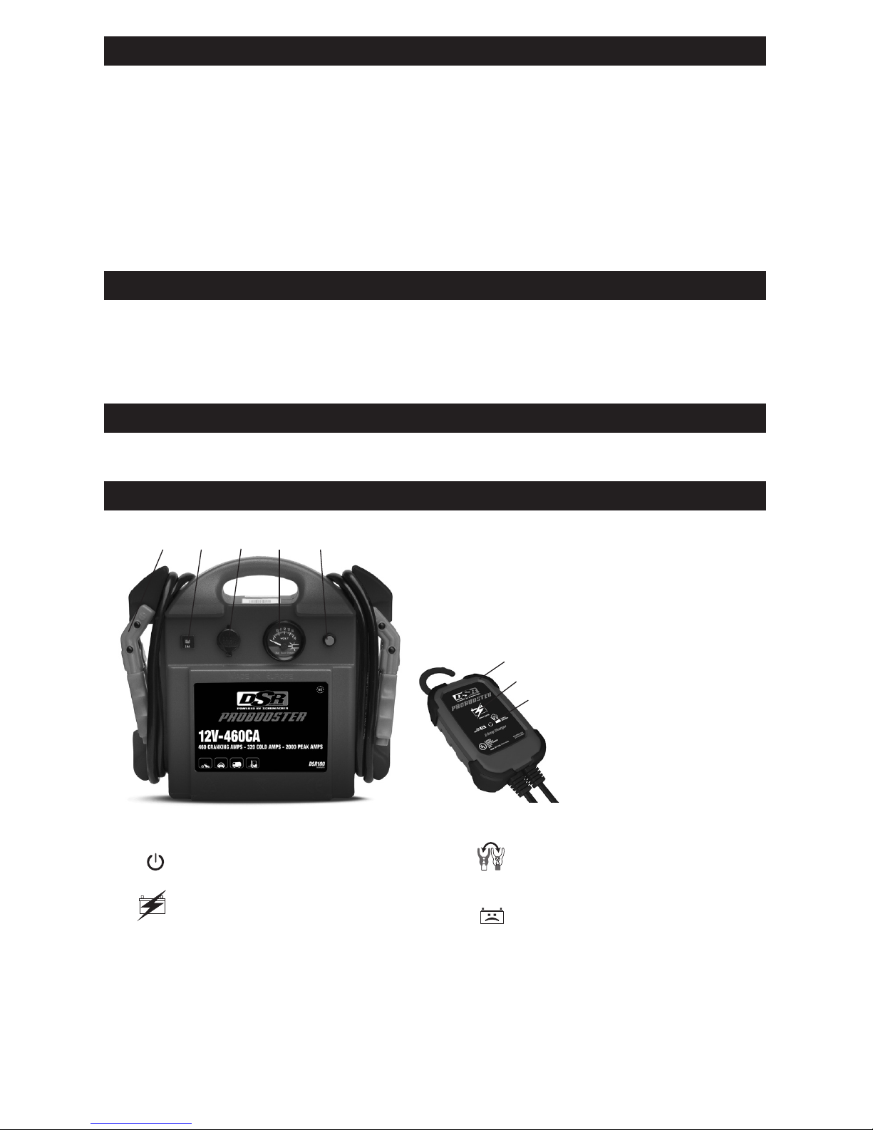
6. FEATURES
1 2 3 4 5
6
7
8
1. Battery clamps
2. Circuit breaker for
12V DC power output
and charge port
3. 12 Volt DC power outlet
and charge port
4. Voltmeter
5. Voltmeter button
6. SC2DSR charger
7. Charging status LED
8. Power LED
9. 12V DC adaptor
(not shown)
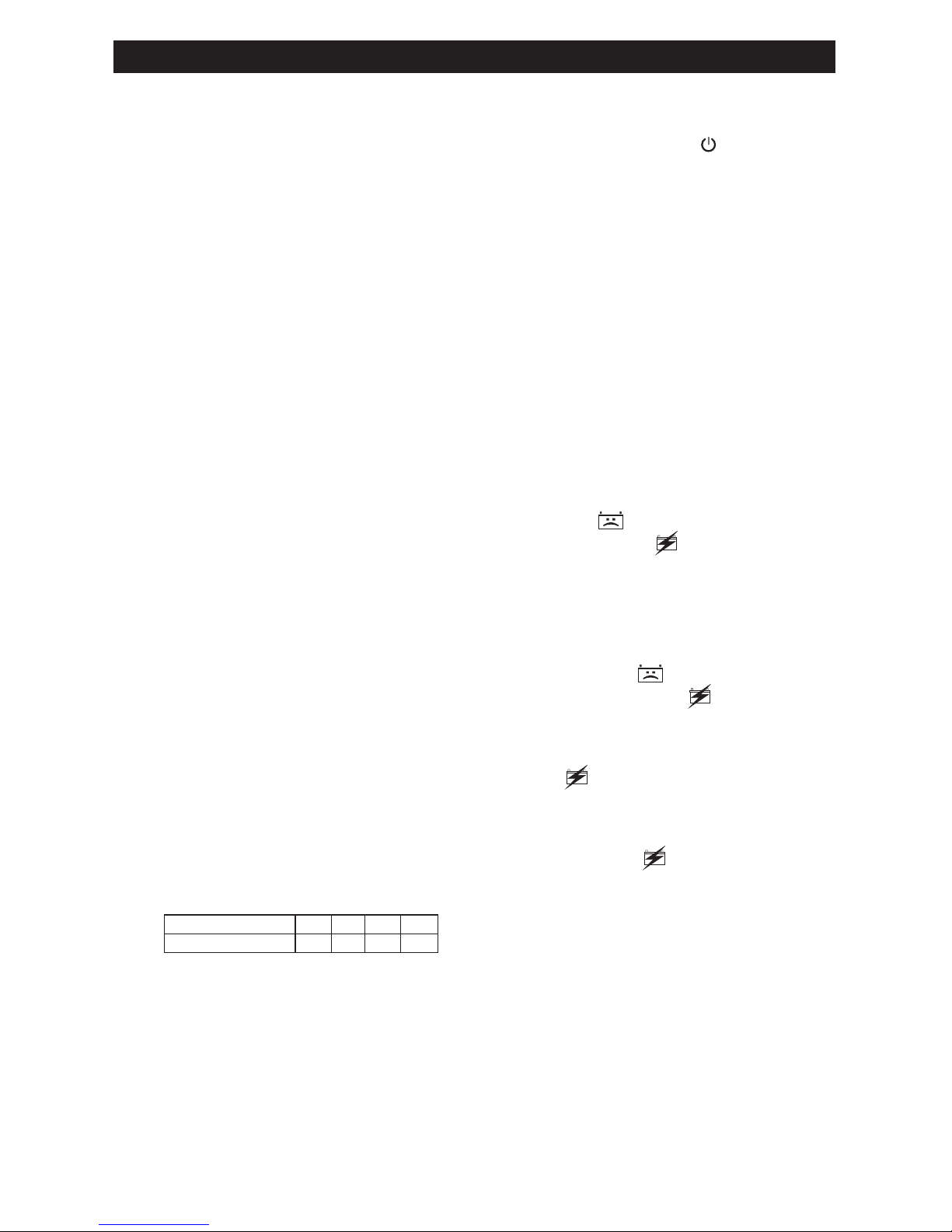
6.1 Charger LED Indicators
POWER (green) LED lit: The
charger is connected to AC power.
CHARGING INDICATOR
Yellow/orange LED lit: The charger
is charging the battery.
Yellow/orange LED ashing:
The charger is in abort mode.
Green LED pulsing: The battery
is fully charged and the charger
is in maintain mode.
CLAMPS REVERSED (red)
LED ashing: The connections
are reversed.
BAD BATTERY (red) LED lit:
The charger has detected
a problem with the battery. See
Troubleshooting for more information.
• 7 •
7. CHARGING THE INTERNAL BATTERY OF THE BOOSTER
• Press the Voltmeter button to show the
charge level of the battery.
• After starting the engine at 2000 rpm,
leave the booster connected to the
vehicle and press the voltmeter button.
The voltmeter will indicate between
14 and 14,4 volts (at 2000 rpm) if the
alternator is functioning correctly.
7.1 Grounding and AC Power Cord
Connections
IMPORTANT. Only use the charger that
was included with the booster to charge
the internal battery of the booster. Using a
different charger could result in personal
injury or property damage.
WARNING!
RISK OF ELECTRIC SHOCK OR FIRE.
This battery charger is for use on a
nominal 120V circuit. The plug must be
plugged into an outlet that is properly
installed in accordance with all local
codes and ordinances. The plug pins
must t the receptacle (outlet). Do not use
with an ungrounded system.
DANGER. Never alter the AC cord or plug
provided – if it does not t the outlet, have
a proper outlet installed by a qualied
electrician. An improper connection can
result in a risk of an electric shock or
electrocution.
An extension cord should not be used
unless absolutely necessary. Use of an
improper extension cord could result
in a risk of re and electric shock. If an
extension cord must be used, make sure:
• That the pins on the plug of the extension
cord are the same number, size and
shape as those of the plug on the
charger.
• That the extension cord is properly wired
and in good electrical condition.
• That the wire size is large enough for the
AC ampere rating of the charger,
as specied:
Length of cord (feet) 25 50 100 150
AWG* size of cord 18 18 18 16
*AWG-American Wire Gauge
7.2 Charging the Booster
1. Connect the end of the 12V accessory
plug quick-connect to the charger.
2. Insert the 12V accessory plug into
the 12V accessory outlet of the jump
starter.
3. Plug the charger’s power cord into
a grounded 120V AC electrical wall
outlet.
4. The charger’s green POWER LED
will light.
5. The yellow/orange LED will light, to
indicate charging.
6. The pulsing green LED indicates the
battery is fully charged.
7. When charging is complete,
disconnect the charger from the
AC power. Then remove the 12V
accessory plug from the booster.
7.3 Charger Modes
Automatic charging mode
When an automatic charge is performed,
the charger switches to maintain mode
automatically after the battery is charged.
Aborted Charge
If charging cannot be completed normally,
charging will abort. When charging aborts,
the charger’s output is shut off. The BAD
BATTERY (red) LED will light and
the yellow/orange (CHARGING) LED
will ash. Do not continue attempting to
charge the battery. Check the battery and
replace, if necessary.
Desulfation Mode
Desulfation could take 8 to 10 hours. If
desulfation fails, charging will abort. The
BAD BATTERY (red) LED will light
and the yellow/orange (CHARGING)
LED will ash.
Completion of Charge
Charge completion is indicated by the
green (CHARGED) LED. When
pulsing, the charger has switched to
maintain mode.
Maintain Mode (Float-Mode Monitoring)
When the green (CHARGED) LED is
pulsing, the charger has started maintain
mode. In this mode, the charger keeps the
battery fully charged by delivering a small
current when necessary. If the charger
has to provide its maximum maintain
current for a continuous 12 hour period,
it will go into abort mode (see Aborted
Charge). This is usually caused by a
drain on the battery or the battery could
be bad. Make sure there are no loads on
the battery. If there are, remove them. If
there are none, have the battery checked
or replaced.

• 8 •
Maintaining the Battery
The SC2 DSR maintains 12V batteries,
keeping them at full charge.
NOTE: The maintain mode technology
allows you to safely charge and maintain
a healthy battery for extended periods
of time. However, problems with the
battery, improper connections or other
unanticipated conditions could cause
excessive current draws. Occasionally
monitoring your battery and the charging
process is recommended.
8. OPERATING INSTRUCTIONS
8.1 Jump Starting a Vehicle Engine
IMPORTANT: Using the booster without a
battery installed in the vehicle will damage
the vehicle’s electrical system.
IMPORTANT: Do not use the booster while
charging its internal battery.
WARNING! A SPARK NEAR THE
BATTERY MAY CAUSE A BATTERY
EXPLOSION. TO REDUCE THE RISK
OF A SPARK NEAR THE BATTERY:
1. Turn the vehicle’s ignition OFF before
making cable connections.
2. Position the DC cables to reduce the
risk of damage by the hood, door and
moving or hot engine parts.
NOTE: If it is necessary to close the
hood during the jump starting process,
ensure that the hood does not touch
the battery clips or cut the insulation of
the cables.
3. Stay clear of fan blades, belts, pulleys
and other parts that can cause injury.
4. Check the polarity of the battery posts.
The POSITIVE (POS, P, +) battery
post usually has a larger diameter
than the NEGATIVE (NEG, N, -) post.
5. Determine which post of the battery is
grounded (connected) to the chassis.
If the negative post is grounded to the
chassis (as in most vehicles), see step
6. If the positive post is grounded to
the chassis, see step 7.
6. For a negative-grounded vehicle,
connect the POSITIVE (RED) clip from
the booster to the POSITIVE (POS,
P, +) ungrounded post of the battery.
Connect the NEGATIVE (BLUE) clip
to the vehicle chassis or engine block
away from the battery. Do not connect
the clip to the carburetor, fuel lines or
sheet-metal body parts. Connect to a
heavy gauge metal part of the frame
or engine block.
7. For a positive-grounded vehicle,
connect the NEGATIVE (BLUE) clip
from the booster to the NEGATIVE
(NEG, N, -) ungrounded post of the
battery. Connect the POSITIVE (RED)
clip to the vehicle chassis or engine
block away from the battery. Do not
connect the clip to the carburetor,
fuel lines or sheet-metal body parts.
Connect to a heavy gauge metal part
of the frame or engine block.
8. Crank the engine. If the engine does
not start within 8-10 seconds, stop
cranking and wait at least 3 minutes
before attempting to start the vehicle
again.
• To allow the voltage of the booster
battery to build up again.
• To allow the renewal of gasses inside
the battery.
• To allow the internal components of
the battery to cool down.
If you do not wait and/or the starting
attempt is too long, you risk losing power,
you reduce your starting possibilities by
the second attempt and you risk melting
the fuse inside.
IMPORTANT:
• Never connect the booster to a battery
or starter which is in short-circuit. The
internal fuse will blow.
• Make sure clamps are connected
correctly.
• Never disconnect the booster while
engine running when there is no
battery in the vehicle or when the
vehicle’s battery is at 0 volt. This may
damage the alternator.
9. After the engine starts, disconnect the
blue clamp (-) and then the red clamp,
(+) in that order.
10. Immediately recharge the booster.
8.2 Internal fuse replacement
The booster is equipped with an internal
fuse. It can melt following a short circuit or
a too-long start attempt.
To monitor the fuse:
• Press on the voltmeter. If it does not
deviate, the fuse has melted.
• Measure the voltage at the clamps:
0 volt = melted fuse.

• 9 •
Fuse specication
AMG Heavy Duty 300A
WARNING! KEEP AWAY FROM SPARKS
AND FLAMES – BATTERY COULD EMIT
EXPLOSIVE GASES.
1. Allow the fuse to cool down
completely (approximately 5 minutes).
2. Make sure the unit is unplugged from
the external charger.
3. Open the back cover to expose the
battery and the fuse.
4. Using a wrench, remove the rst nut
and bolt securing the fuse on the
battery. Repeat the same steps for
the second nut and bolt. Remove the
open fuse and replace it with a new
one of the same type and rating.
5. Tighten the nuts and bolts to secure
the fuse, and then replace the cover.
6. The unit is now ready to use.
8.3 Powering a 12V DC Device:
The booster is a power source for all 12V
DC accessories that are equipped with
a 12V accessory plug. Use it for power
outages and shing or camping trips.
1. Make sure the device to be powered
is OFF before inserting the 12V DC
accessory plug into the 12V DC
accessory outlet.
2. Open the protective cover of the DC
power outlet on the front of the booster.
3. Plug the device into the outlet and turn
the device on (if required).
4. If the device draws more than 16A
or has a short circuit, the internal
circuit breaker of the booster will
trip and disconnect the power to
the device. Disconnect the device
and manually reset the breaker by
pressing the red button.
IMPORTANT: The DC power outlet is
wired directly to the internal battery.
Extended operation of a 12V device may
result in excessive battery drain. Recharge
immediately after unplugging the device.
9. MAINTENANCE INSTRUCTIONS
9.1 After use and before performing
maintenance, unplug and disconnect the
booster.
9.2 Use a dry cloth to wipe all battery corrosion
and other dirt or oil from the battery clips,
cords, and the booster’s case.
9.3 Ensure that all of the booster’s
components are in place and in good
working condition, including the plastic
boots on the battery clips.
9.4 All servicing should be performed by
qualied service personnel.
10. MOVING AND STORAGE INSTRUCTIONS
10.1 IMPORTANT:
• CHARGE IMMEDIATELY AFTER
PURCHASE
• KEEP FULLY CHARGED
The internal battery will gradually
self-discharge (lose power) over time,
especially in warm environments. Leaving
the battery in a discharged state may
result in permanent battery damage.
10.2 Store inside, in a cool, dry place.
The ideal storage temperature is between
50°-77°F (0°-25°C).
10.3 Clamps must be stored on their support
posts, to make sure they do not come to
contact with any metallic surface.
10.4 If the booster is moved around the shop
or transported to another location, take
care to avoid/prevent damage to the
cords, clips and the unit. Failure to do so
could result in personal injury or property
damage.
IMPORTANT: Do not use and/or store
the booster in or on any area or surface
where damage could occur if the internal
battery should unexpectedly leak acid.

• 10 •
11. SPECIFICATIONS
Booster
Internal battery type ....................................................Maintenance-free AGM lead-acid
Nominal voltage ..................................................................................................12V DC
Capacity ................................................................................................................. 20 Ah
DC power outlet (max. continuous load) ................................................................... 16A
Peak amps .............................................................................................................. 2000
Cranking amps .......................................................................................................... 460
Cold cranking amps .................................................................................................. 320
Jumper cables.........................................................................................25 mm2, 51.18"
Dimensions ........................................................................... 14.76 x 4.33 x 12.6 inches
Weight .................................................................................................20.94 lbs. (9.5 kg)
Charger
Input Voltage. .............................................................................120V AC @ 60Hz, 0.5A
Output Voltage ..........................................................................................................12V
Output Current Rating ..................................................................................... 2A @ 12V
12. REPLACEMENT PARTS
Booster
Meter ......................................................................................................... 5399200032Z
Push button ............................................................................................... 0499000177Z
Circuit breaker........................................................................................... 3999002161Z
Internal battery (12V, 20Ah) ...................................................................... 5799000041Z
Battery clamps .......................................................................................... 2299002912Z
Fuse (AMG heavy-duty, 300A) .................................................................. 3999002113Z
Charger
SC2DSR charger ...................................................................................... 2299002872Z
12V accessory plug (quick-connect). ........................................................ 3899003573Z
13. TROUBLESHOOTING
Booster
PROBLEM REASON SOLUTION
The booster does not recharge. The AC outlet is dead.
Poor electrical connection.
The booster is not connected
correctly.
16A 12V accessory plug breaker
is tripped.
The battery is bad.
Check for open fuse or circuit
breaker supplying AC outlet.
Check power cord and extension
cord for a loose tting plug.
Verify the connections from the
booster’s charging plug to the
battery.
Press the red button, to
manually reset the breaker
on the charge port.
Replace the battery.
 Loading...