

Page 1
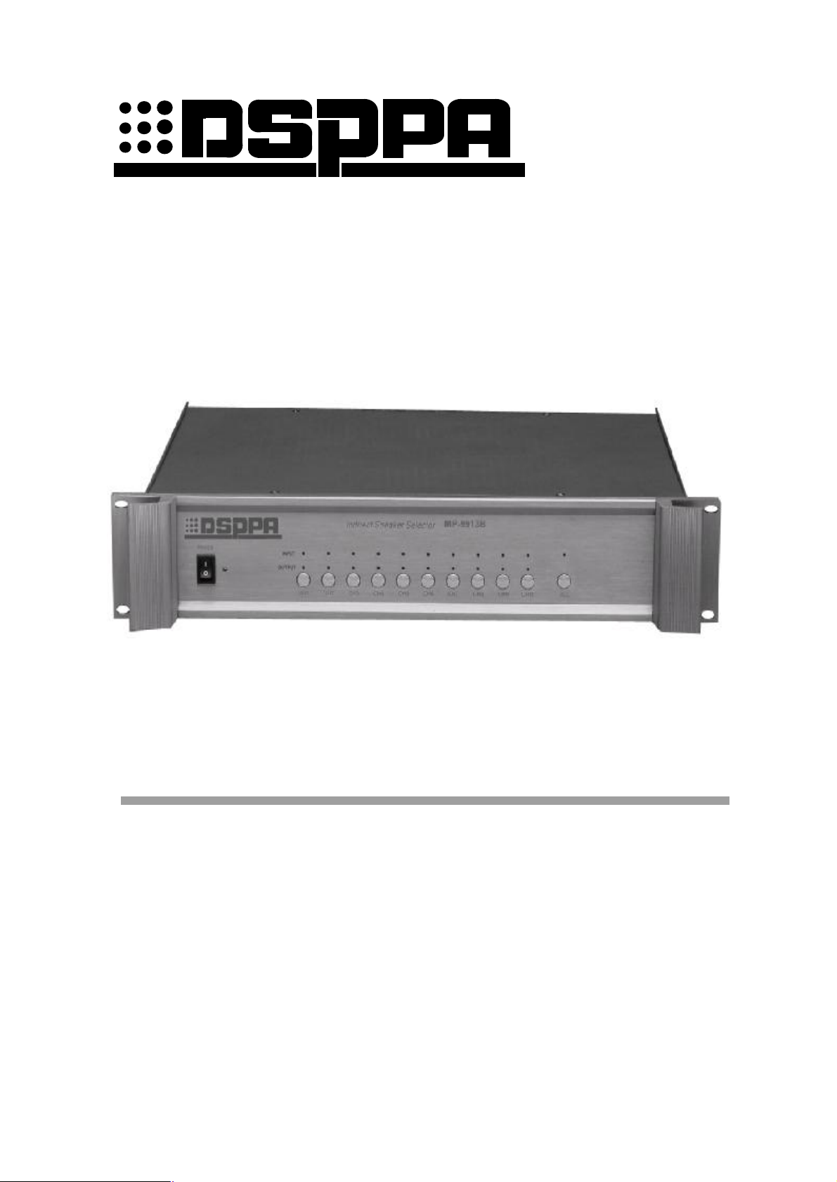
MP9913B
Indirect Speaker Selector
OWNER’S MANUAL
Before operating, please read this manual completely.
FEATURES
l 2CH inputs, 10CH outputs.
l Hi/Low alarm level available.
l The channel will be switched to input B automatically while alarming.
l Alarm indicator and output indicator.
1
Page 2

Left blank for memo
2
Page 3
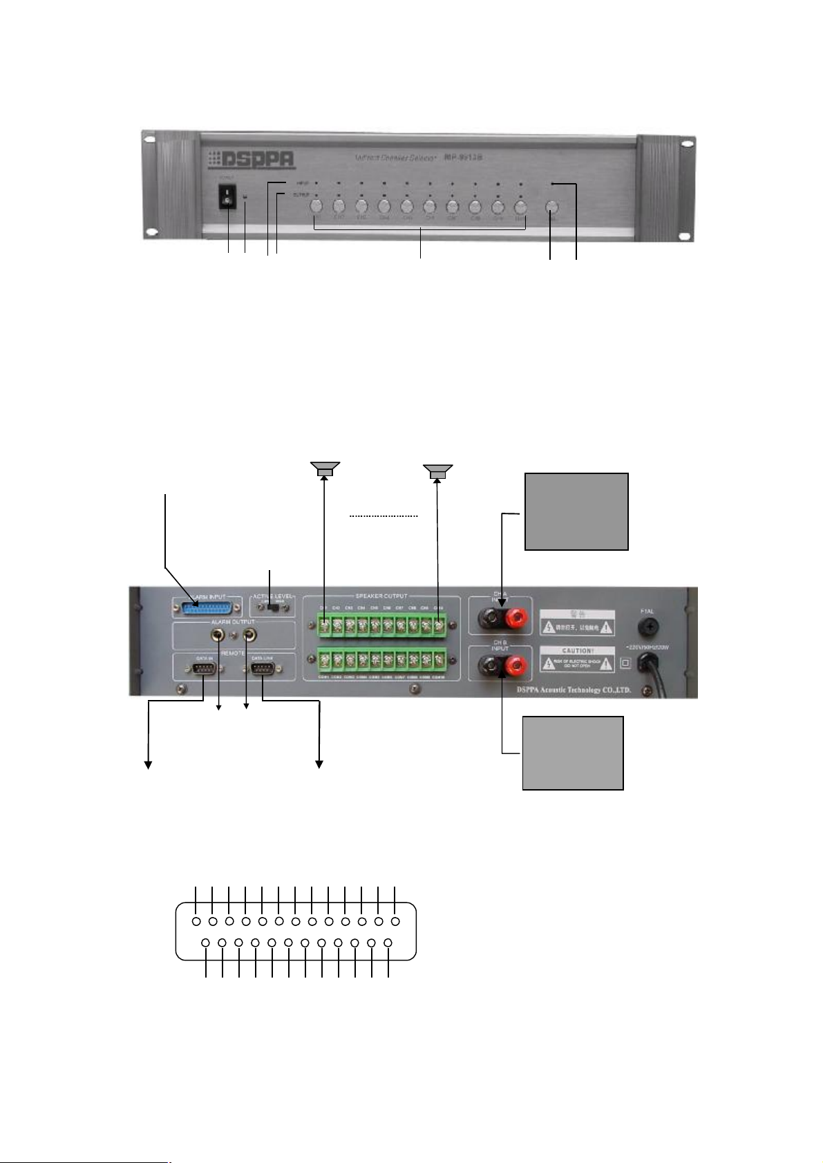
FRONT PANEL
Input level
1 2 3 4 5 6 7
1 Power switch (1 is power on and the “power LED” is on ) ,
2 Power indicator 5 Switching key
3 Switch indicator 6 All call button
4 Output indicator 7 All call indicator
REAR PANEL & CONNECTIONS
Emergency
from FIRE center*
preset
MP9914T
ALM OUTPUT to
Timer / Siren Device
To MP9906D
or MP9907C
Power Amp. A
MP series
(for BGM)
Power Amp. B
MP series
(for EMC)
ALARM IN to be connected to fire center
1 2 3 4 5 6 7 8 9 10 11 12 13
14 15 ,16 ,17 18 19 ,20 21, 22 23 ,24 ,25
l 1~10 Live Terminals of CH1~CH10 respectively
l 11~25 COM
3
Page 4

OPERATION
1. Make BGM signal input from A terminal while EMC signal input from B terminal on the rear panel.
We also can make A, B together with short circuit if there is none of appropriative EMC amplifier.
2. Click down any Switching key to switch channels which you want.
3. Click All call button with its LED lit and all Switch indicators lit. In this case, all Switching keys
are no use. Click All call button again and its LED gone off, In this case, all Switching keys are
use.
4. Pin 1 ~ 10 of “ALARM IN”port are live terminals of CH1~CH10 respectively while pin 11~
25 are com. +5 ~ 24V / 0V level of alarm signal is available. If ACTIVE LEVEL set at High,
positive signal is valid; while set at Low, 0V (grounded) signal is valid. Every channel will be
switched to B while alarm signal is fed to ALARM IN, and the Switch indicator will be flashing
quickly.
5. An grounded Alarm signal will be sent out from“ALARM OUT”while any alarm signal appears
on“ALARM INPUT”.
SPECIFICATIONS
Channels 10, switchable
Input capacity
output capacity
ALM 10 CHs; +5~+24 V/ 0 according to presetting
Protection
Power Requirement
Dimensions
Gross weight 6.5 kg
Net weight 5.2 kg
Specifications are subject to be changed without notice.
● When the “Power switcher” is off, please pull out the power cord from the socket.
● Please keep the equipment out of water.
● To reduce the risk of electric shock, do not remove the cover.
● No user parts inside. Refer servicing to qualified service personnel
70 ~ 100 V ,10 A
70 ~ 100 V ,5 A / CH
AC fuse ×1
AC 220 –240 V / 50~60 Hz
485×88×375 mm
CAUTION
DSPPA Acoustic Technology Co., Ltd.
4
Page 5
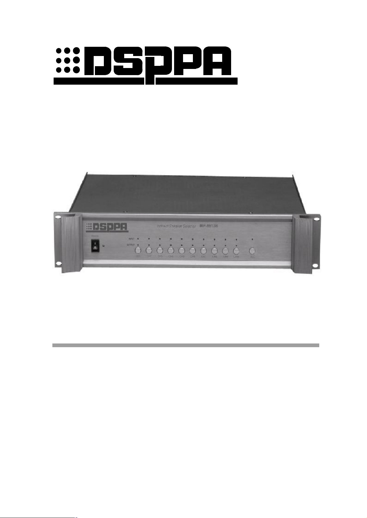
MP-9913B
广播分区器
使用说明
欢迎惠顾。您对本产品之选用显示了您的专业眼光。使用前请详细阅读本说明书。
性能特点
l 2 路输入(A 和 B), 10 通道输出。
l 2 种输入告警电平选择。
l 紧急广播强插功能。
l 一目了然的告警指示和输出信号指示。
5
Page 6

此页留空供用户记事。
6
Page 7
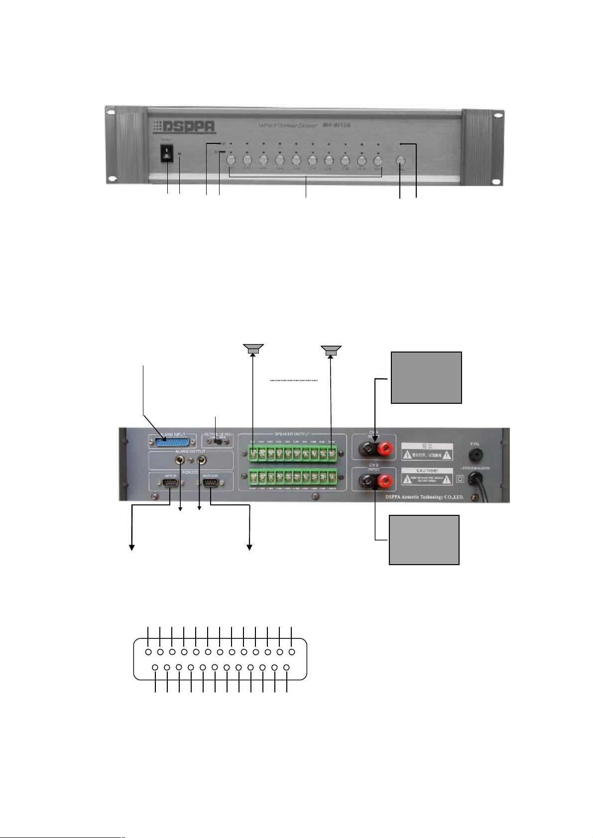
前面板
1 2 3 4 5 6 7
1 电源开关(按下 1 为电源接通状态且电源指示灯亮)
2 电源指示 5 分区选择键
3 分区选通指示 6 全开全关控制开关 ,
4 输出指示 7 全开全关指示
后面板及连接
警报信号
来自消防中心
告警设定
接 MP9914
报警信号输出
去定时器/报警器
接 MP9906D 或
MP9907C
A 功放
MP 系列
(背景音乐)
B 功放
MP 系列
(紧急广播)
*ALARM INPUT 同消防中心连接
1 2 3 4 5 6 7 8 9 10 11 12 13
14 15 ,16 ,17 18 19 ,20 21, 22 23 ,24 ,25
l 1~10 热端,分别对应于 CH1~CH10
l 11~25 公共端
7
Page 8

使用方法
1. 背景音乐信号由后面板 A 端子输入,紧急广播信号由 B 端子输入(如无紧急广播专用功放,
可把 A、B 端子并接)。
2. 按某一分区选择键可选通该分区,同 时相应的分区选通指示灯亮,再按一下即可关闭,同时
相应的分区选通指示灯熄灭。
3. 按下“全开全关”控制键,其相应的指示灯点亮,其他十个分区控制键的指示灯也同时点亮,
此时其他的十个分区控制键不能控制分区。再次按下“全开全关”控制键时,其相应的指示
灯熄灭,此时其他的十个分区控制键才可控制分区。
4. 警报输入口“ALARM IN”(见连接图)的第 11~25 端子为公共地线;第 1 号~10 号端子
分别对应管理 CH1~CH10 十个通道,输入信号可以是+5V~+24V 的正极性信号或短路信
号(输入电流小于 3mA)。当告警设定开关置于 High 时,正信号有效;当该设定开关置
于 Low 时,短路信号有效。有告警时相应通道扬声器乃自动强切到 B 输入,且对应的分区选
通指示灯会快速闪烁。
5. 警报输入口“ALARM INPUT” 任一端子有警报信号输入时,报警信号输出口“ALARM
OUT”即有报警信号输出,可用于启动处于待机状态的定时器以及激发警报信号发生器。
性能规格
通道数
输入容量
输出容量
警报信号
保护
电源
尺寸
毛重
净重
性能规格如有改变恕不另行通知。
● 本设备的电源开关在“断”状态时,机器并未与电网电源完全断开,为安全起见,在不 使用
10, 可任意选通
70 ~ 100 V , 10A (功率输入)
每个通道 70 ~ 100V , 5A (功率输出)
+5V~+24V, 0V~0.5V(短路)可预置
AC 保险丝×1
AC 220 –240 V / 50~60Hz
485×88×375mm
6.5kg
5.2kg
注 意
本设备时,请将电源线插头拔出插座。
● 本设备不能遭受水滴或水溅且不能将装满水的花瓶之类的物品放置在设备上。
● 请勿随意打开机器盖板,以防触电。必要时须由有专业证书之专业人员进行修理。
DSPPA Acoustic Technology Co., Ltd.
8
 Loading...