

Page 1
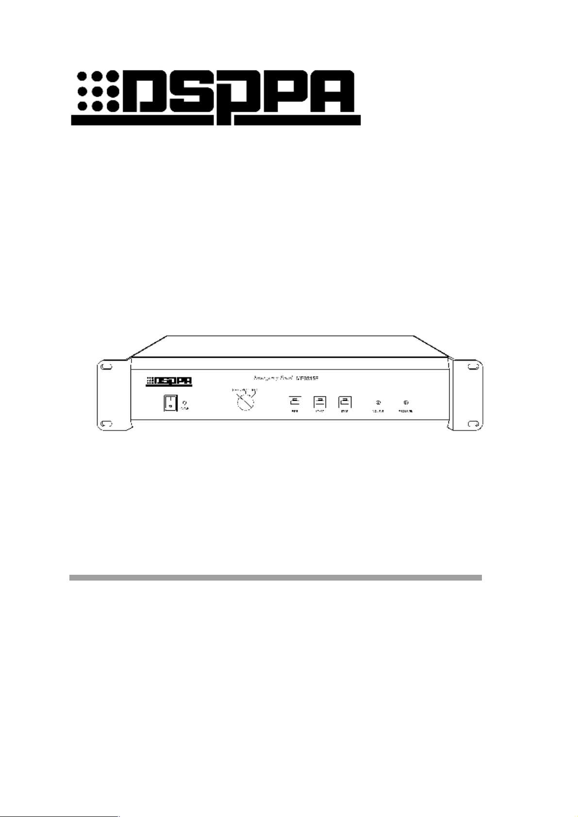
MP9815E
EMERGENCY PANEL
OWNER’S MANUAL
Before operating, please read this manual completely.
FEATURES
l Alarm triggering and siren or recorded signal output.
l 1 minutes digital REC / PLAY IC.
l Record Level control.
l Output volume control.
Page 2
* * Emergency Panel
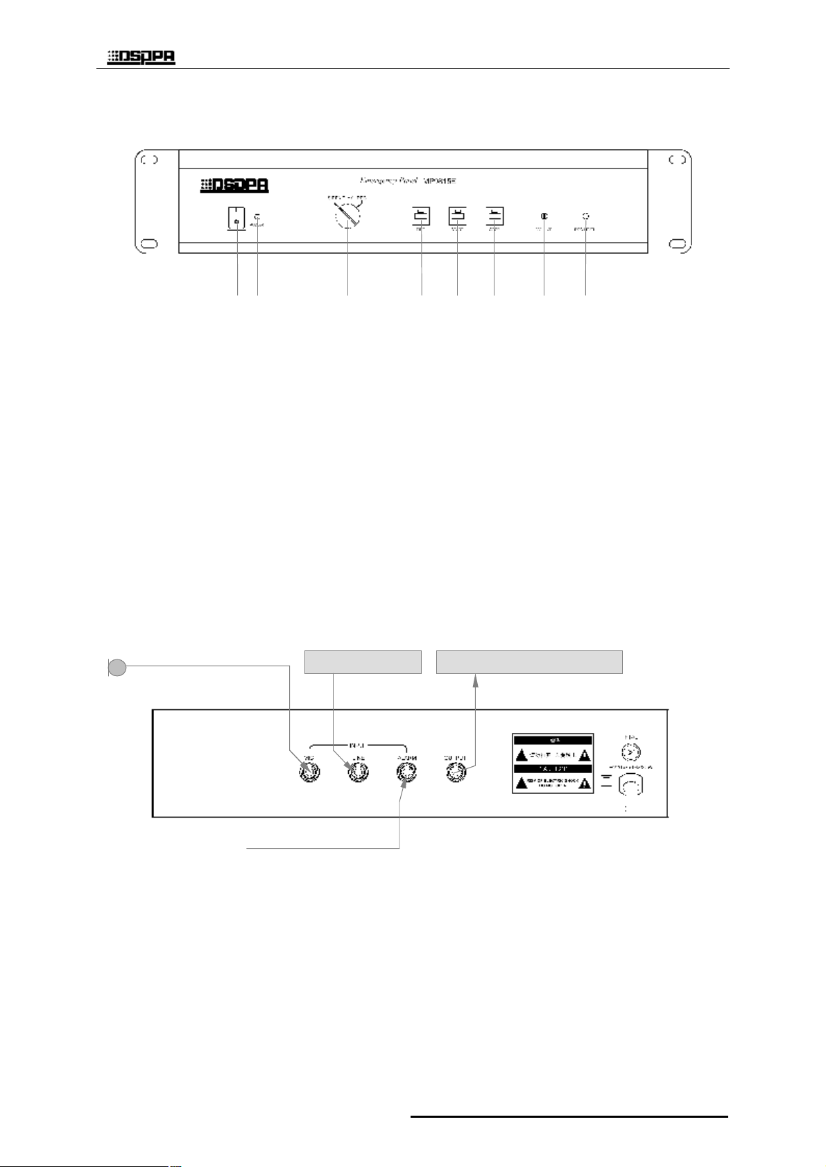
FRONT PANEL
1 2 3 4 5 6 7 8
1 Power switch 4 FIRE : manual siren.
2 Power indicator 5 START : start recording or playing.
3 OPTION 6 STOP : stop recording or playing.
SIREN : siren signal output. 7 Output level control.
PLAY : recorded signal output. 8 REC level control.
REC : record into IC inside.
REAR PANEL & CONNECTIONS
for recording
DECK MP9816
Pre Amp. MP9811P
emergency
MP9815E
1
Guangzhou DSPPA Audio Co., Ltd.
Page 3

* * Emergency Panel
OPERATING
1、Auto mode
Plug in the mains regardless the position of“POWER”switch and adjust the knob
“VOLUME”properly.
l Alarm with siren Put “OPTION”switch at“SIREN” position, as soon as an alarm
signal comes into the “ALARM” port,siren will be sent out from “OUTPUT” port
until alarm released.
l Alarm with a message recorded Put “OPTION”switch at “PLAY”position,
as soon as an alarm signal comes into the“ALARM”port,message recorded in inner IC
will be sent out from “OUTPUT”port repeatedly until alarm released.
2、 Manual mode
Plug in the mains, turn on“POWER”switch and adjust knob “VOLUME”properly.
l Alarm with siren Put “OPTION”switch at“SIREN”,as soon as press down“FIRE”
button siren will be sent out from “OUTPUT”port until the button released.
l Alarm with a message recorded Put “OPTION”switch at “PLAY”position,click
“START”button once,message recorded in inner IC will be sent out from “OUTPUT”
port until click “STOP” button or the message comes to the end. While the message
sending out it also be broken off by click“START”button once again.
3、Recording
Set“OPTION”switch at “REC”position and set “REC LEVEL”at middle position
then turn the“POWER”switch on. Click“START”button,signals from “LINE”
or“MIC”will be recorded into inner IC chip until press“STOP”button, and it also stop
at 1 minutes later too.
MP9815E
2
Page 4

* * Emergency Panel
SPECIFICATIONS
Inputs Mic : 2mV 10kΩ; Line : 1V 10kΩ;
Alarm : 0V/+24V(or open), 0V (short circuit) is valid
Output SIREN or Recorded Message: 1V
Rec. IC inside, 60s.
Frequency response
Protection AC fuse
Power Requirement AC 220-240V/50-60Hz
Outer Packing Size (mm)
Unit Size (mm)
Gross weight 8.8kg
Net weight 7.1kg
Specifications are subject to be changed without notice .
100Hz-10kHz(±3dB)
(L×W×H)530×440×195
(L×W×H)484×365×88
CAUTION
● When the “Power switcher” is off, please pull out the power cord from the socket.
Please keep the equipment out of water.
● To reduce the risk of electric shock, do not remove the cover.
● No user parts inside. Refer servicing to qualified service personnel.
Guangzhou DSPPA Audio Co., Ltd.
MP9815E
3
Page 5

* * 报 警 器
MP9815E
警 报 器
使用说明
欢迎惠顾。您对本产品之选用显示了您的专业眼光。使用前请详细阅读本说明书。
性能特点
l 警报触发或手动触发, 警笛或固化录音输出。
l 内置一分钟录音 IC,可录可放。
l 录音电平控制。
l 输出音量控制。
4
MP9815E
Page 6

* * 报 警 器
录音用
前面板
1 2 3 4 5 6 7 8
1 电源开关 4 火警: 报警
2 电源指示灯 5 启动: 启动/暂停 录音或放音
3 选择开关 6 停止: 停止录音或放音
警 笛: 警报时输出警笛信号 7 输出音量控制
放录音: 警报时输出固化录音 8 录音电平控制
录 音: 固化录音
后面板及连接
录音用
卡座 MP9816
前置放大器 MP9811P
警报信号输入
5
Guangzhou DSPPA Audio Co., Ltd.
MP9815E
Page 7

* * 报 警 器
使用方法
1、自动方式(由警报信号触发告警)
机器电源插头接通 220V 交流电源,适当调节音量“VOLUME”旋钮。电源开关“POWER”可
以打开也可以不打开。
l 警笛报警 — 把选择开关“ OPTION”置 于 警笛“ SIREN”位置,此时只要后面板的警报口“ALARM”
输入短路信号,输出口“OUTPUT”乃输出警笛信号,直至短路信号解除。
l 放录音报警 — 把选择开关“ OPTION”置 于 放音“ PLAY”位置,此时只要后面板的警报口“ALARM”
输入短路信号,输出口“OUTPUT”乃输出已固化的录音信号,自动循环,直至短路信号解除。
2、手动方式(手动发警报)
机器接通电源后,适当调节 “VOLUME”旋钮,将音量调至合适大小。打开电源开关“POWER”
(开关置于‘ I ’位)。
l 警笛报警 — 把选择开关“ OPTION”置 于 警笛“ SIREN”位置,此时只要按下火警“ FIRE”按钮,
输出口“OUTPUT”乃输出警笛信号,直至“FIRE”按钮弹起。
l 播放录音报警 — 把选择开关“OPTION”置于放音“PLAY”位置,按一下启动“START”键,输
出口“OUTPUT”乃输出一段已固化的录音信号。再按“START”键乃暂停,按 “STOP”键则停
止播放。一段录音放完时也会自动停止播放。
3、录音之固化
把选择开关“OPTION”置于录音“REC”位置,把录音电平控制旋钮“REC LEVEL”置于中间位
置。接通电源开关,按一下启动“START”键,乃可由“LINE”口或“MIC”口输入信号进行录音,
固化在机内 IC 之中。按停止“STOP”键乃停止录音。启动后 1 分钟也会自动停止录音。倘需分段录
音,则可在分段处按一下“START”键暂停,再按一下“START”键继续录制。录完后应进行试放,
必要时视试放效果调节录音电平旋钮后重新录音。
6
MP9815E
Page 8

* * 报 警 器
性能规格
输入
输出 警笛音或固化录音: 1V
固化录音 内置 IC, 60 秒
频响 100Hz-10kHz(±3dB)
保护 AC 保险丝
电源
外包装尺寸(mm ) (长×宽×高)530×440×195
机器尺寸(mm) (长×宽×高)484×365×88
毛重
净重
性能规格如有改变恕不另行通知。
Mic: 2mV 10kΩ; Line: 1V 10kΩ;
Alarm: 0V/+24V(或开路), 0V (短路) 有效
AC 220-240V/50-60Hz
8.8kg
7.1kg
注 意
● 本设备的电源开关在“断”状态时,机器并未与电网电源完全断开,为安全起见,在不使用
本设备时,请将电源线插头拔出插座。
● 本设备不能遭受水滴或水溅且不能将装满水的花瓶之类的物品放置在设备上。
● 请勿随意打开机器盖板,以防触电。必要时须由有专业证书之专业人员进行修理。
Guangzhou DSPPA Audio Co., Ltd.
7
MP9815E
 Loading...