

DSPPA MP8712, MP8735, MP8745 User Manual
Public Address System
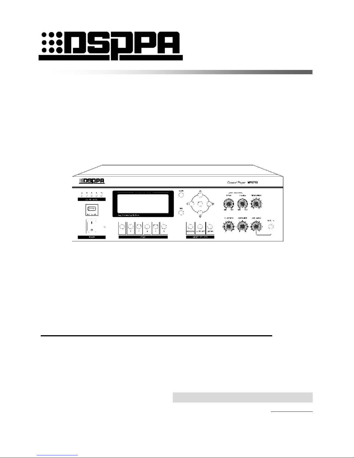
Multi-function Player MP8712
MP8735
MP8745
User ’s Manual
Thank you for using DSPPA Public Address System. Please carefully read this manual first for better use.
DSPPA Acoustic Technology Co., Ltd.
http: //www.DSPPA.com

* * Fire Protection/Public Address System Multi-function Player
MP8735
1
Contents
Installation Precautions..........................................................................................................2
Features.................................................................................................................................2
Front Panel............................................................................................................................3
Rear Panel..............................................................................................................................4
Wiring of Power Amplifier.....................................................................................................5
Operation Instructions – Operation and Status Interface.........................................................7
Precautions............................................................................................................................12
1. Safety Precautions..................................................................................................12
2. After-sales Service Precaution................................................................................12
Specifications.........................................................................................................................13
Appendix...............................................................................................................................14
Application of File Format of USB Disk................................................................................14
List of Built-in Programs in USB Disk...................................................................................14

* * Fire Protection/Public Address System Multi-function Player
MP8735
2
Do not cover the vents.
1. Do not use the system in case of damage to the power cord.
3. The power socket shall be compatible with the power plug.
4. Do not use the power amplifier in a poorly ventilated, dusty or wet place, nor expose it to direct sunlight.
Always keep away from heat source. Never apply vibration to the power amplifier.
l Public address system with built-in MP3 player, radio, timer, zone controller and pager.
l Runs programs by control of timer and has graphic interface with multi-level menus.
l Built-in MP3 player and tuner.
l FM/AM tuner with up to storable 40 radio stations.
l Selectable internal 1GB memory and external USB disk for MP3 player.
l With double USB interfaces, supports .MP3 files stored in a common USB disk, MP3 player, mobile HDD,
card reader, etc.
l 3 channels of LINE IN, 3 channels of MIC IN and 1 channel of LINE OUT.
l Mute function available for MIC 1 and LINE 1 facilitates playing by priority.
l Uniform treble and bass control for all channels and independent volume control for individual channel.
l Timer-controlled program for one-week operation, up to 100 time schedules programmable for each day,
and time schedules and programs that will not be lost in case of power failure.
l Two sets of timing plan, each of which can be edited for 7 days, and up to 100 time schedules for each day.
l 1 channel of AC220V timer-controlled output power socket and one short output interface controlled by
timer control.
l Timer-controlled built-in MP3 or tuner programs can be played according to time schedules that are
cycled by week.
l The starting time of a time schedule is accurate to a second.
l Power amplifier P1 output as well as 70V and 100V fixed-voltage output.
l 6-zone outputs enable switching on or off 6 zones according to the time schedule, of which voltage output is
100V.
l LCD with automatic backlight.
l 5 LED output level indicators.
l Just one device offers all functions of a complete set of public address system.
Installation Precautions
Features
* * Fire Protection/Public Address System Multi-function Player
MP8735
3
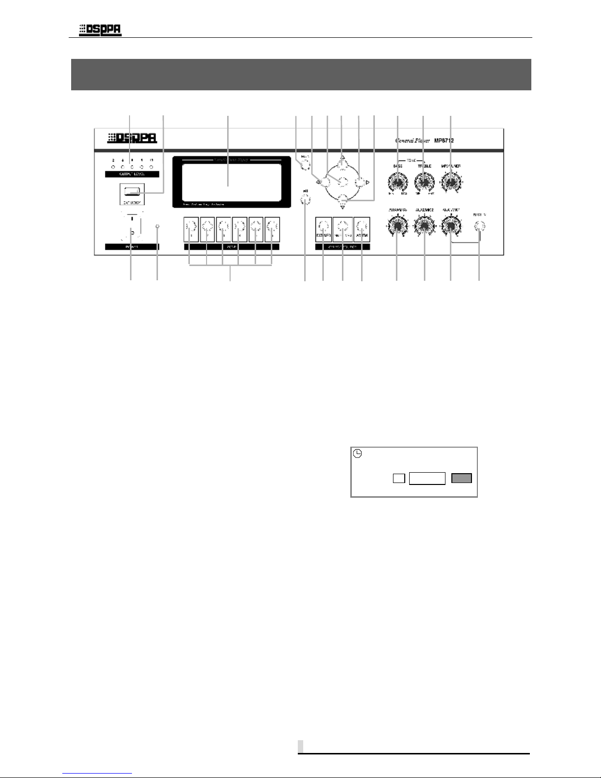
1 On/Off switch
Turn the switch to the “I” position to switch on the
power, or turn the switch to the “o” position to switch
off the power.
2 Power indicator
The indicator is turned on when the power is turned
on, and turned off when the power is turned off.
3 6-zone manual switch
A zone is controlled by the corresponding key which
is touched to turn on or off the zone. The on/off status
is shown on the bottom of LCD.
4 Play/Pause/Radio Mute key
This key is used to play or make a pause in MP3
player mode, and is used to mute in radio mode.
5 External MP3 player mode key
Press this key to switch to external MP3 player in any
menu interface.
6 Built-in MP3 player mode key
Press this key to switch to built-in MP3 player in any
menu interface.
7 Radio mode and band key
Press this key in any menu interface to switch to
radio mode, and switch between FM and AM bands
in radio mode.
8 5 LED output level indicators
The 5 LED indicators indicate the size of output
levels from the power amplifier. If the 5th indicator is
turned on, overload exists and corresponding
adjustment should be performed. Turn the volume
knob to flash the 4th and 5th indicators.
9 USB interface
The USB interface is used as program source
interface for MP3 player, and supports storage
devices, such as common USB disks and mobile
HDDs.
10 LCD
The LCD shows the status of function operation.
11 Selection key shown on main interface
Press the selection key under any menu, and the main
interface as shown below will appear.
12 Move key for option operation
Press this key to move the cursor leftwards to the
desired option for selection.
13 Ok key
Press this key to confirm the current operation or
access the menu of lower level. Also, press the key
under the main interface to manually turn on/off the
timer power or operate the program control.
14 Number increase or adjustment key
Press this key to increase the number for operation
concerning number adjustment, e.g. press the key to
increase the frequency in radio mode, to select the
next program in MP3 mode, or to select one of
options under certain status.
Front Panel
1 2 3 4 5 6 7 20 21 22 23
8 9 10 11 12 13 14 15 16 17 18 19
Sat 08:35:00 Source: Built-in Audio
1 off 2 off 3 off 4 on 5 on 6 off
Power supply:
Current time: Tue 08:00:
Off
Program
control start
Setup
* * Fire Protection/Public Address System Multi-function Player
MP8735
4
15 Move key for option operation
Press this key to move the cursor rightwards to the
desired option for selection.
16 Number reduction or adjustment key
Press this key to increase the number for operation
concerning number adjustment, e.g. press the key to
increase the frequency in radio mode, to select the
previous program in MP3 mode, or to select one of
options under certain status.
17 Bass knob
This knob is used to adjust the bass, which is turned
clockwise or counterclockwise to increase or reduce
the bass.
18 Treble knob
This knob is used to adjust the treble, which is turned
clockwise or counterclockwise to increase or reduce
the treble.
19 MP3/Radio volume knob
This knob is used to adjust the volume of MP3/radio.
When the volume is turned off, no sound is output in
MP3/Radio mode.
20 AUX3/MIC3 IN volume adjustment knob
This knob is used to adjust the volume of LINE IN 3
and MIC 3. The signal adjusted is determined by
selector switch on the rear panel. If the switch is
turned to the AUX3 position, the volume of LINE 3
can be adjusted; if the switch is turned to the MIC3
position, the volume of MIC 3 can be adjusted.
21 AUX2/MIC2 IN volume adjustment knob
This knob is used to adjust the volume of LINE IN 2
and MIC 2. The signal adjusted is determined by
selector switch on the rear panel. If the switch is
turned to the AUX2 position, the volume of LINE 2
can be adjusted; if the switch is turned to the MIC2
position, the volume of MIC 2 can be adjusted.
22 AUX1/MIC1 IN volume adjustment knob
This knob is used to adjust the volume of LINE IN 1
and MIC 1. The signal adjusted is determined by
selector switch on the rear panel. If the switch is
turned to the AUX1 position, the volume of LINE 1
can be adjusted; if the switch is turned to the MIC1
position, the volume of MIC 1 can be adjusted.
23 MIC 1 interface
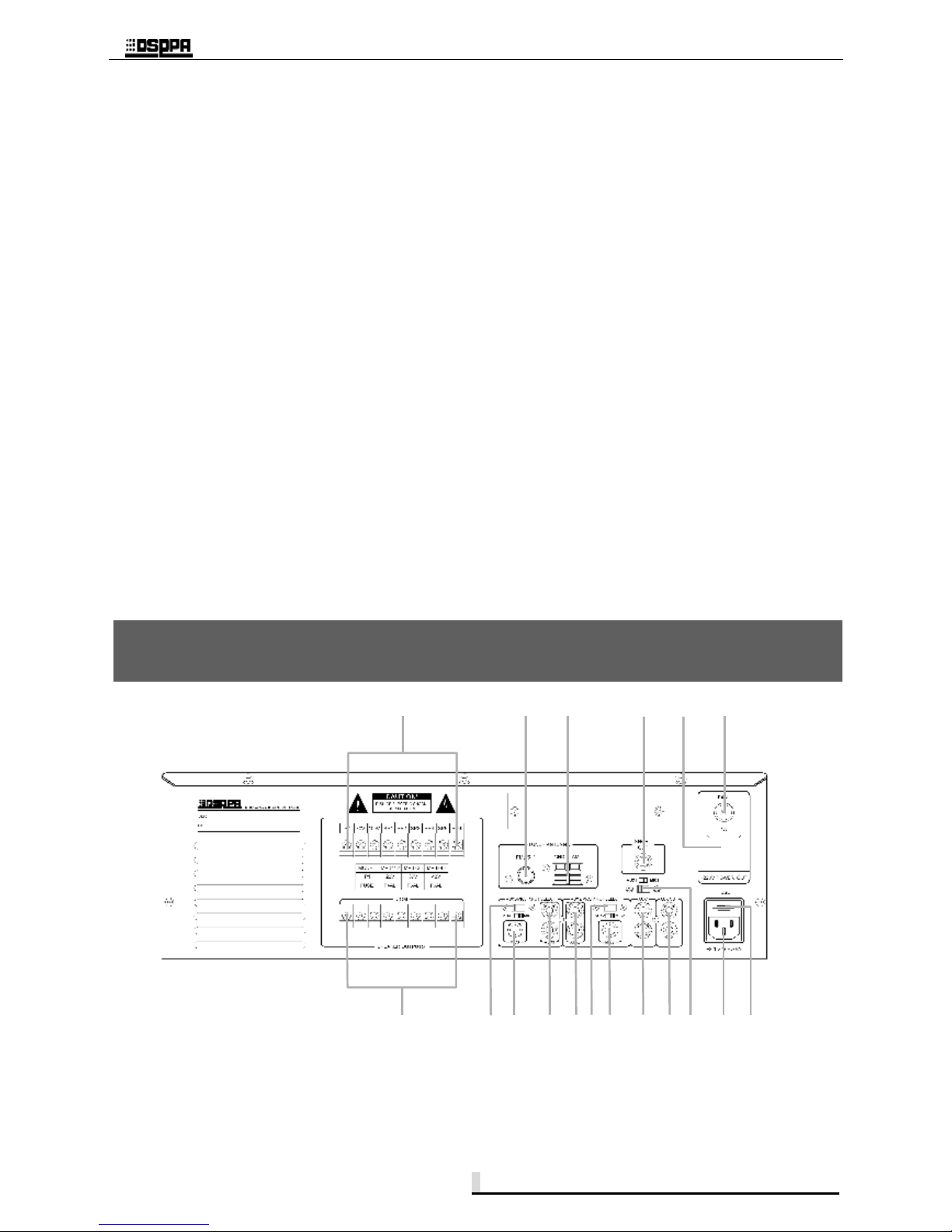
1 Power amplifier output COM terminal
Fixed amplifier output resistance, 70V, 100V and
6-zone COM terminals.
2 Power amplifier output HOT terminal
For details about the amplifier output HOT terminal,
refer to the following text.
Rear Panel
1 18 17 16 15 14 13 12 11 10 9 8
2
3
4
5
6
7
* * Fire Protection/Public Address System Multi-function Player
MP8735
5
3 FM antenna
Connects an FM antenna.
4 AM antenna
Connects an AM antenna. Please note the ground
terminal when connecting.
5 Short OUT interface
The short OUT interface is used to provide
short-circuit signal to devices requiring short-circuit
signal. The short-circuit signal is controlled by the
timer power supply.
6 Timer power output socket
This socket offers an AC220V voltage to other
device, which is controlled manually or by time
schedule.
7 Timer power supply fuse
In case of fuse blowing, please replace the fuse with a
new one with the same specifications. If this failure
still exists, please check the circuit for failure.
8 AC220V output power fuse
In case of fuse blowing, please replace the fuse with a
new one with the same specifications. If this failure
still exists, please check the circuit for failure.
9 AC220V power socket
The power socket is used to connect to the mains for
power supply of the system.
10 AUX1/MIC1 IN selector switch
The AUX1 and MIC1 use a common input channel. If
the switch is turned to the AUX position, the line
signal is input; if the switch is turned to the MIC
position, the microphone signal is input.
If signals from line and microphone are input to one
channel at the same time, select the selector switch to
adjust the volume of one of the signals.
11 AUX OUT interface
This interface is used to connect to an audio monitor,
such as a power amplifier.
12 AUX1 IN interface
This interface is used to connect to an audio source,
such as a CD player, tuner and cassette.
13 MIC2 IN interface
14 AUX2/MIC2 IN selector switch
The AUX2 and MIC2 use a common input channel. If
the switch is turned to the AUX position, the line
signal is input; if the switch is turned to the MIC
position, the microphone signal is input.
15 AUX2 IN interface
This interface is used to connect to an audio source,
such as a CD player, tuner and cassette.
16 AUX3 IN interface
This interface is used to connect to an audio source,
such as a CD player, tuner and cassette.
17 MIC3 IN interface
18 AUX3/MIC3 IN selector switch
The AUX3 and MIC3 use a common input channel. If
the switch is turned to the AUX position, the line
signal is input; if the switch is turned to the MIC
position, the microphone signal is input.
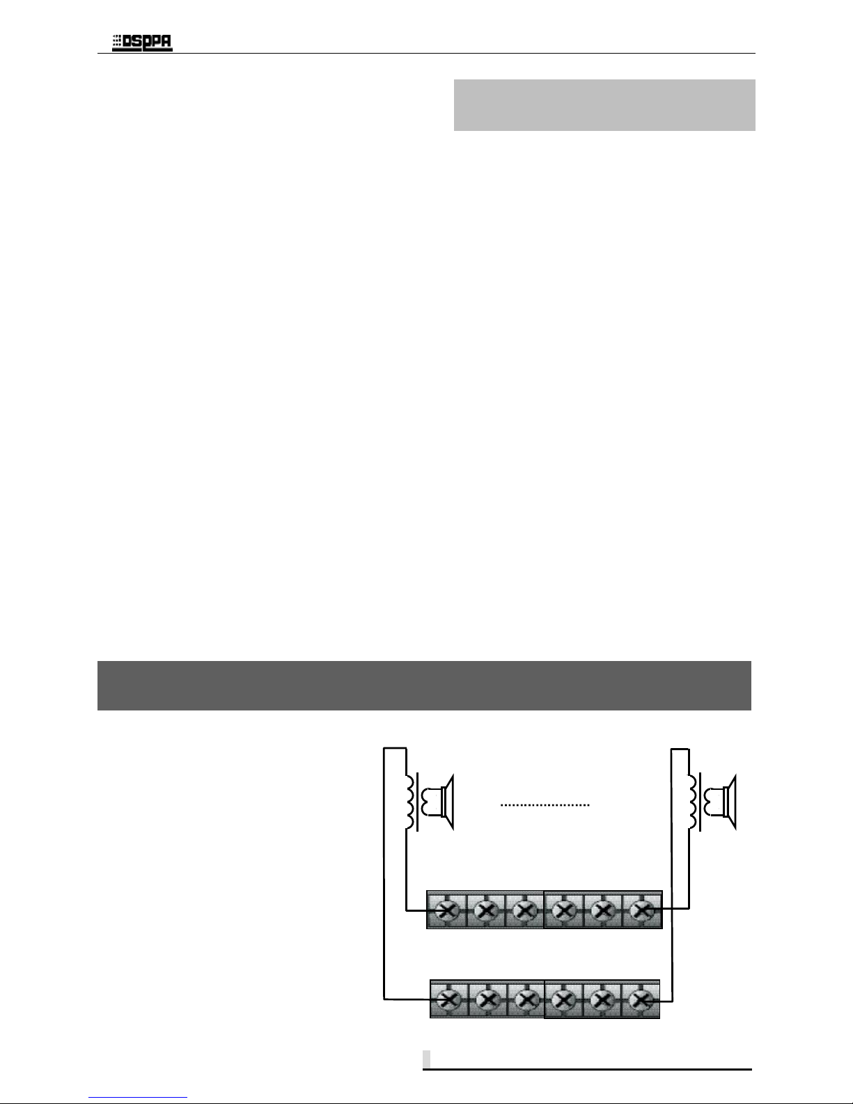
1 Wiring diagram of zone output
The output voltage of each zone is 100V. To
connect the zone output, refer to the right
diagram and note that the HOT and COM
terminals are different. Speakers connected
to zones should be provided with
transformer.
Caution: Make sure that the power supply
is turned off when wiring.
Wiring of Power Amplifier
Speaker with
transformer
Speaker with
transformer
SP1 SP2 SP3 SP4 SP5 SP6
COM COM COM
COM COM COM
Zone 1
Zone 6
 Loading...