

Page 1
1
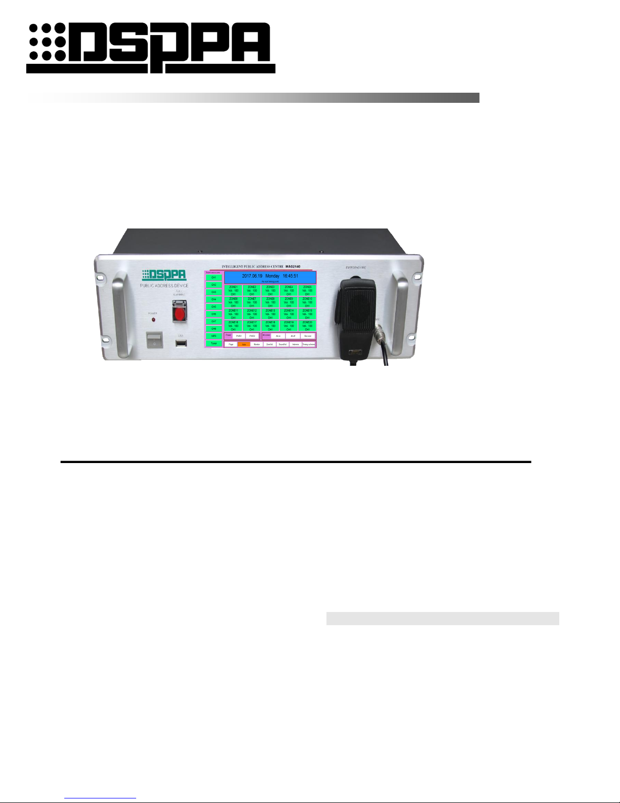
Public Address System
Micro Intelligent Public Address System
MAG2120II
MAG2140II
User’s Manual
Thank you for using DSPPA public address system. To ensure optimal operation of this equipment, please read these
operational instructions carefully before using.
Guangz h o u DSPPA Audio C o .Ltd
http://www.DSPPA.com
http://www.dsppstech.com
Page 2

2
Information on Operation Instructions
This Operation Instructions involves MAG2120II and MAG2140II micro intelligent systems for
public address system, including function introduction and appearance introduction of products,
connection illustrations, settings, operation instructions, precautions, after-sale services, product
performance and specifications. Please read this Operation Instructions carefully before connection
and operation.
All contents in this Operation Instructions are based on operation of MAG2140II, which are only
for illustration. Furthermore, operation methods for MAG2120II are similar to that of MAG2140II.
For future use, please make a good disposition of this manual
Page 3

3
Content
1. System Overview ............................................................................................................................................................................ 4
2、Performance characteristics .......................................................................................................................................................... 4
3、Appearance and Functions ............................................................................................................................................................ 5
4、Connection Description ................................................................................................................................................................ 8
5、Operation Instructions ..................................................................................................................................................................12
6、 Other Functions ..........................................................................................................................................................................31
Packing list .........................................................................................................................................................................................34
Specifications .....................................................................................................................................................................................36
1 Safety Precautions ...........................................................................................................................................................................37
2. Precautions for After-sale Services ............................................................................................................................................38
ATTACHMENT ................................................................................................................................................................................39
Remote Control (Optional) ................................................................................................................................................................40
Page 4

4
1. System Overview
Micro intelligent public address system integrates such functions as playing, intelligent timing control, audio matrix,
partition control, intelligent firefighting linkage, remote computer control as well as telephone and remote paging.
Owing to its integral public address functions and individualized intelligent control functions, this address system can
better satisfy demands of users of medium and small address systems, such as amplification at such public places as
primary and high schools, medium and small plants, parks and square.
This address system falls into two types as per the number of control zone, namely MAG2120II and MAG2140II.
MAG2120II and MAG2140II can control 20 and 40 zones respectively to provide more options for users.
2、Performance characteristics
1. A public address controller integrating has such functions as playing, intelligent timing control, audio matrix and
partition control.
2. It has 5 timing programs. Each timing program is provided with 500 timing points for 7-day circulation. Each timing
point is available for control of audio source selection, bell, built-in MP3, AM/FM, 2-way power source, 4 types of
external peripheral audio sources (CD, tuner, socket and MP3 program player). The 5 timing programs are easy for
switch-over.
3. 8-route common audio source input, built-in MP3, AM/FM, 1-route local aviation microphone input 1st prior
function), 1-route alarm signal input (2nd prior function), 1-route remote paging microphone signal input (3rd prior
function) and 40-route output large audio matrix.
4. 40-route emergency firefighting input (short-circuit signal), 1-route firefighting linkage output (short-circuit signal
used for expansion, which is available for connection with MP99/8815E, MP99/8823S and so on) (each route of
emergency input is available for triggering of any programmable and random zone)
5. It is available for connection with external computers through LAN interface for control of the host computer via
software (realize auto play as per fixed time, location and program through remote setting). (Such function is to be
realized by remote control software as purchased separately)
6. It is available for expansion of remote paging microphone through 9 pin ports.
7. All timing programs are available for instantaneous and easy manual intervention.
8. It is available for real-time monitoring of each zone and volume control (mechanical volume control).
9. It is equipped with ARM9 platform and 5.6-inch color screen + touch pad.
10. It is provided with USB interface used to copy songs in the USB directly to the host computer for play.
11. It can realize 100m wireless remote control with 12 programmable buttons. It can realize customized on/off of zone
and selection of audio source and songs with one button.
12. It is provided with 3 types of bell signal output functions (mechanical volume control).
13. It is provided with alarm signal output function (mechanical volume control).
14. It is provided with telephone zone paging functions (mechanical volume control, password alteration,
comprehensive paging, optional paging and programmed paging).
15. It is available for timing control of playing status of external audio source.
16. It can realize calibration of touch points on the touch screen.
17. It can be remote control through the road input signal digital volume control function.
18. It can be remote control through 40 way output digital volume control function.
Page 5
5
3、Appearance and Functions
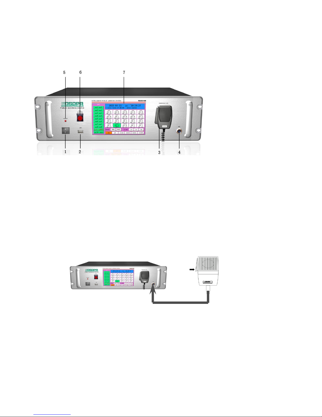
3.1 Front Panel
1. Power Switch
Press I and O to switch on and off the power source respectively.
1. USB Interface
It is connected with such memorialize as USB stored with MP3 programs and mobile HD for copying of programs to
MP3 player, which is available for plug-in of the mouse with USB plug.
3. Microphone Buckle
Be sure to insert the buckle on the back of microphone into this hole when the microphone is not in use.
4. Microphone Interface
Signal of the microphone as connected to this interface has the ultimate priority, which can cover all output signals.
The plug connection mode is as follows. Please refer to the instruction manual for the use of the microphone.
5. Power Indicator Light
Indicator light will flash and distinguish respectively when the power is switched on and off.
6. Total Alarm Button
It is applicable to send alarm signals to all zones by the system total alarm button. Button indicator light will flash
when the alarm signal is being sent. Button indicator light will extinguish, and the button will spring up once the
button is pressed to switch off the alarm.
7. Display Screen / Touch pad
Display screen is for dynamic display of system information and operation of touch screen.
Page 6
6
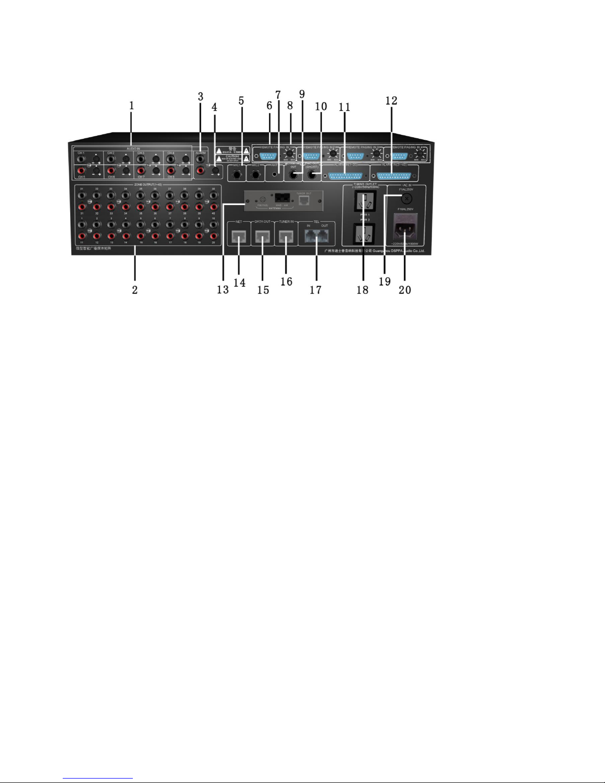
3.2 Back Panel
1. 8-route Audio Source Input Interface and Volume Control Knob
8 independent audio source input channels are available for connection with 8 external audio sources. Each channel is
provided with one independent volume control knob.
2. 40 Audio Matrix Output Interfaces
Each audio output interface is corresponding to a zone for connection with power amplification audio input interface.
3. External Alarm Signal Input Interface
It can be connected with MP99/8815E (alarm generator) to input alarm signal into the machine and open the corresponding
partition alarm automatically. The signal interface has a secondary priority function, secondary priority function only to
aviation microphone on the front panel.
4. Alarm Volume Regulation Knob
It is used to control volume of alarm signal as input by MP99/8815E.
5. 2-way MIC microphone interface
2 microphone interface parallel to CH1, CH2 line input.
6. Remote Pager Connection Interface
9-pin D-type data port can be directly connected to remote paging device or paging hub for expansion of numerous remote
pagers.
7. Wireless Remote Controlled Receiving Antenna Interface
Connect wireless remote control antenna to this interface. For details, please refer to Description of Wireless Remote
Control Functions.
8. Remote Pager Volume Control Knob
It is available for mechanical control of volume of remote pager.
Page 7

7
9. Alarm link output interface
10. The power output linkage interface
11. Zone 1-20 Alarm Signal Input Interface
Input signals from firefighting center.
12. Zone 21-40 Alarm Signal Input Interface
Input signals from firefighting center.
13. Built-in Radio Head Module
For radio head module, please refer to Connection of Radio Head Module.
14. Network Interface
It is connected with LAN for remote control of the system.
15. Data Interface
It is for timing control of external audio sources, which is connected with data exchange interface with external audio
source.
16. Radio Signal Input Interface
TUNER OUT interface connect with radio head module aims to input radio signals to the machine for play of radio audio
sources.
17. Telephone Interface
IN interface aims to connect telecommunication signals to this machine; whereas OUT interface is expected to link up with
other telephone sets.
18. Timing power supply linkage short circuit output interface
It provides AC 220V working power supply to external device to control output status via the timing points.
19. AC Fuse Holder
Please use fuse of the same specification to replace damaged one. There might be line faults to the machine in case of
continuous blowout of fuse. Be sure to check the line, and use fuse of the same specification to replace the damaged one
once the fault is recovered.
20. AC220V Power Input Faucet
This interface is used for switch-in of working power supply to the machine. Be sure insert the plug before connection with
power grid in case of connection.
Page 8
8
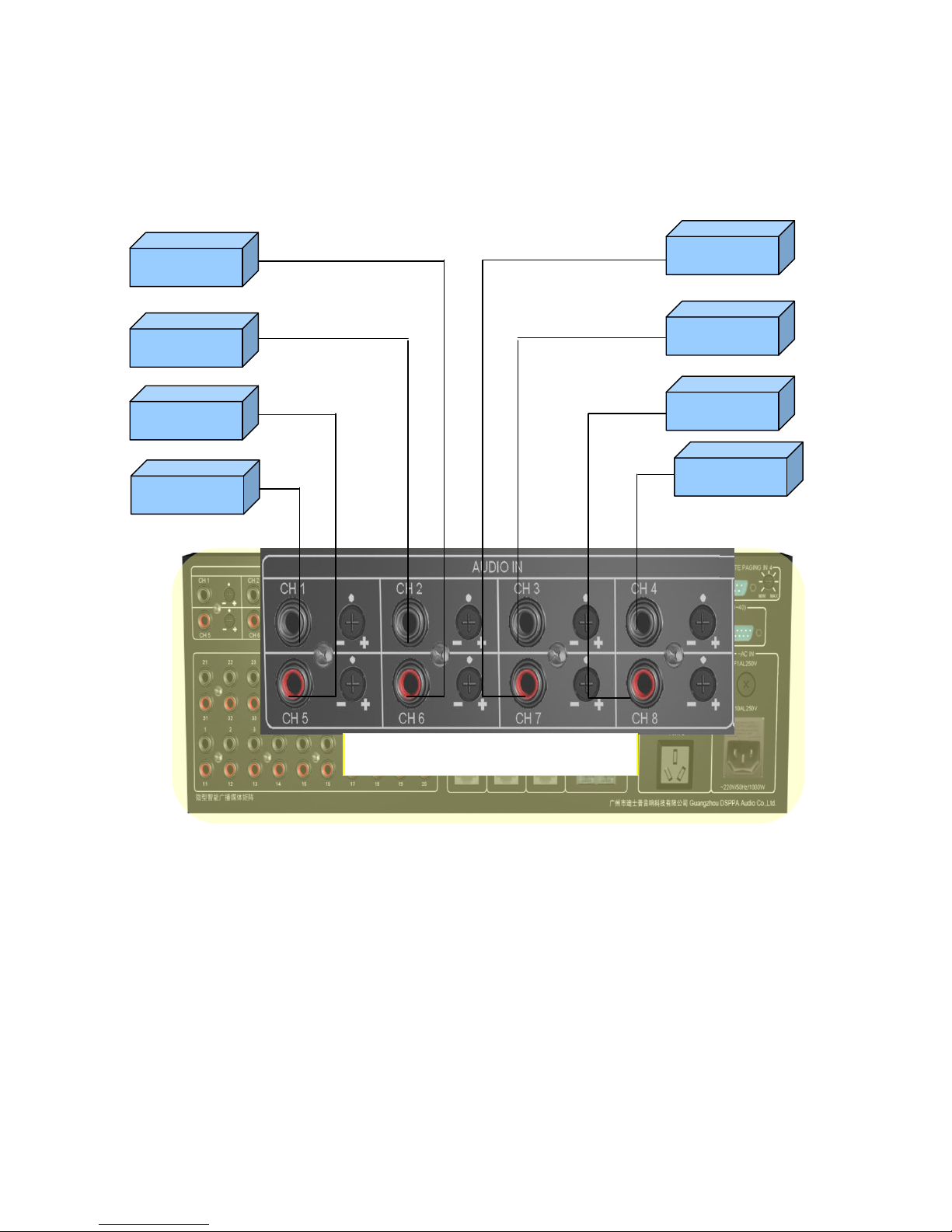
4、Connection Description
4.1 Input Connection Description
(Audio sources as indicated in the following figure are for illustration only; any user may proceed with connection at his or
her discretion.)
音源 4 DVD
Audio source 1 CD
Audio source 2 PC
Audio source5 AUX1
Audio source 7 external
MP3
Audio source 3 VCD
Audio source 8 external
radio
Audio source 6
Audio4 DVD
8-route audio source input interface is on the left upside of the rear
panel
Page 9
9
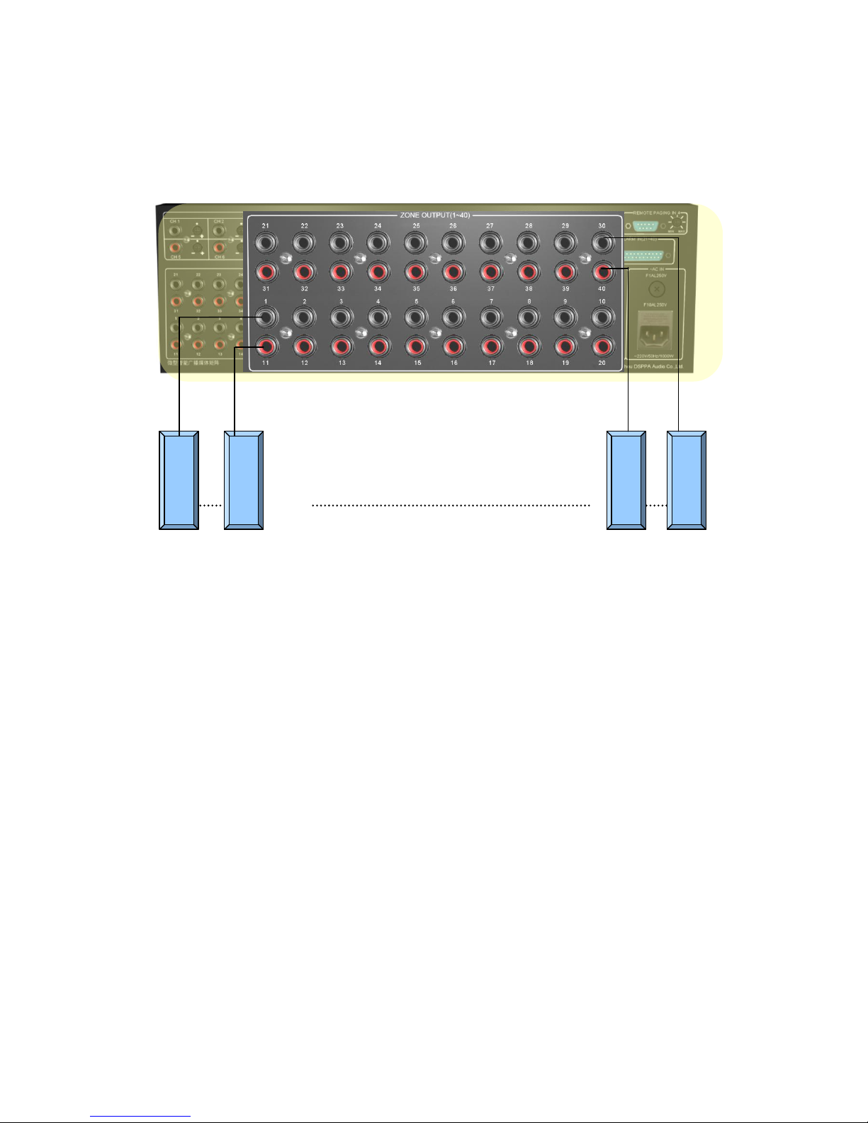
4.2 Description of Output Connection
This machine is expected to distribute 8 external audio sources and 2 built-in ones to 40 audio output ports for output to 40
zones. Each zone is provided with one set of power amplifier to receive audio signals from this machine. Refer to the
following figure
PA in Zone 1
PA in Zone 11
40 output ports connected with power
PA in Zone 40
PA in Zone 30
Page 10
10
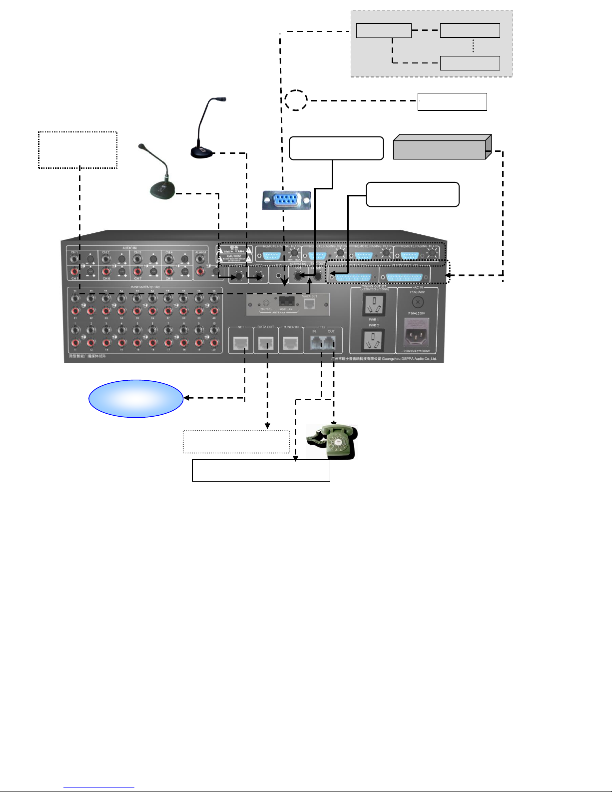
4.3 Other Connections
Description:
Make sure that placement of wireless receiving antenna is close to the receiving orientation of wireless remote controller to
obtain more satisfactory receiving effect and longer receiving distance.
D-type port is available for direct connection with remote pager or paging hub for expansion of numerous remote pagers.
Network
Telephone signal
Outside audio source
Fire center
MIC1
Wireless remote
control receiving
Alarm linkage
Power linkage
Paging hub
Remote paging
Remote paging 0
Can be connected
Remote pager
Page 11
11
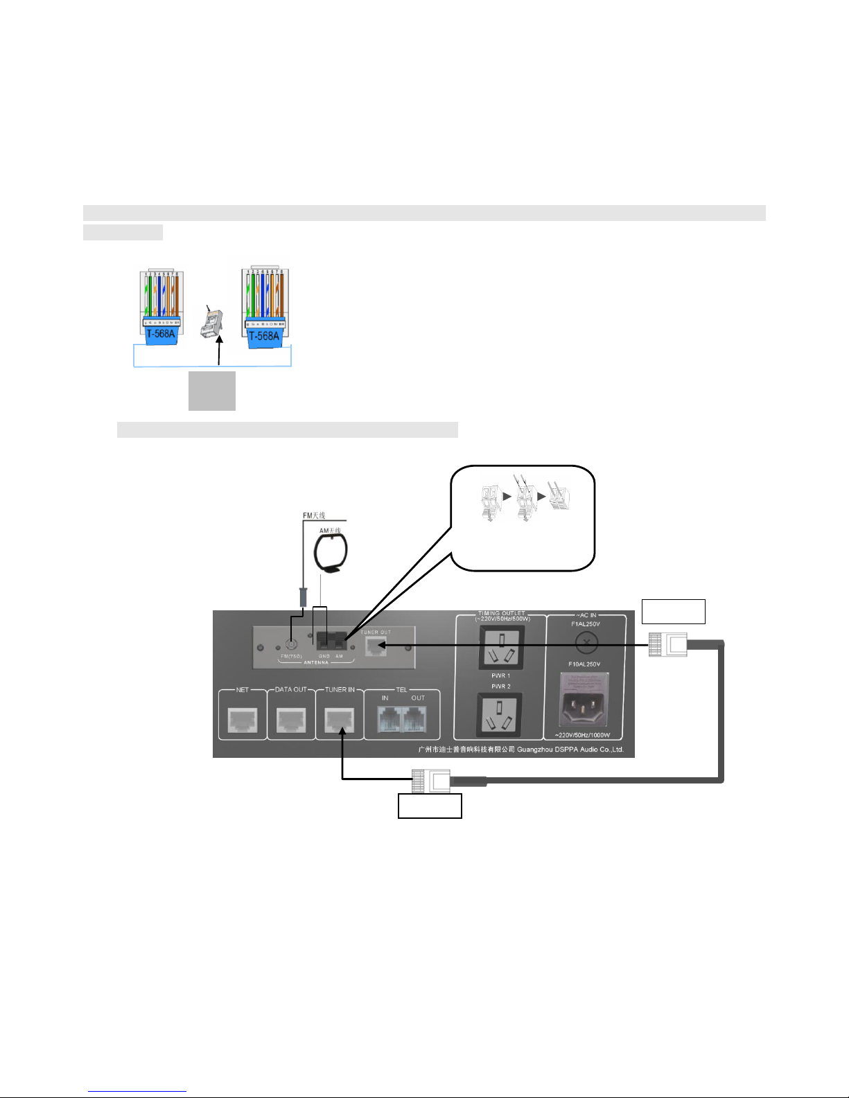
4.4 Connection of Radio Module
Radio function of this machine is realized by the module, which is available for separation. It is applicable to place
radio module at the position of strong receiving signals for connection with extended network line so as to ensure effective
improvement of receiving effect. Radio module is connected with this machine with T586 network line. Module as installed
on this machine is also available for butt joint on the rear panel through network line.
Prompt: Please fabricate extended connecting line in reference to the following figure if radio module is to be
disconnected:
Radio connection mode is as shown in the following figure.
Connection for radio module installation
RJ45 interface
Colors for left-right connection
Green-white, green, orange-white and blue
Blue-white, orange, brown-white, brown;
Pinch cock
opposite to
Insert Hole
Loosen
TUNER OUT
TUNER OUT
Page 12
12
5、Operation Instructions
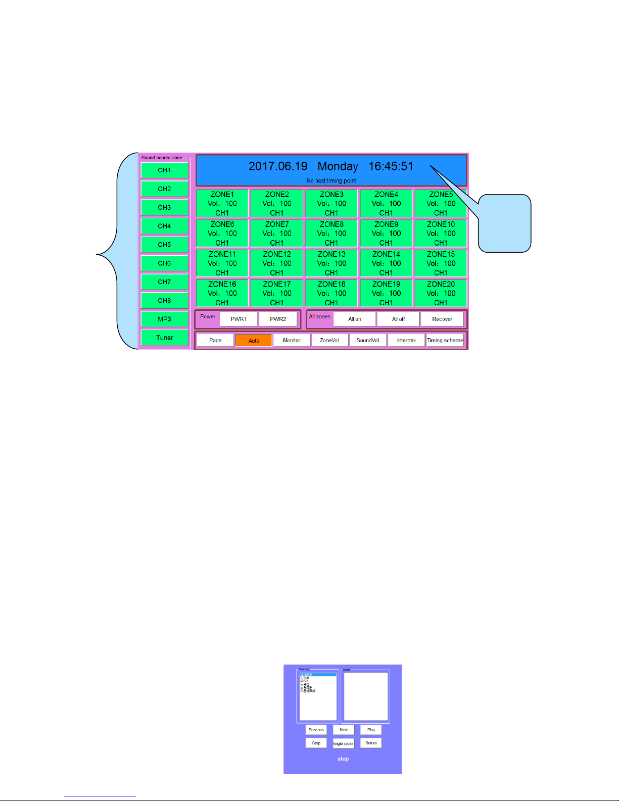
5.1 Main Interface
“Welcome! Process Starting, please waiting” will be displayed on the screen once the power is switched on to start the
machine. It is applicable to enter the main interface as shown in the following figure after start-up.
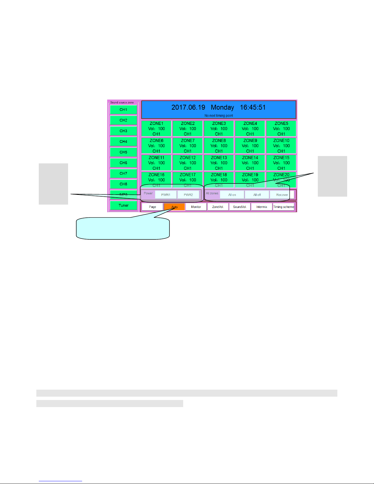
(Figure 1) Main Interface
As shown in the aforesaid figure, information as displayed on the main interface include 10 audio sources, current time,
status and operation of 40 zones, power output control status and operation, programmed/manual control setting, monitoring
setting, timing program selection and system access setting.
1) Distribution of external audio sources
Enter the main interface to play programs in corresponding zones. Firstly, select corresponding audio source for distribution
to the zone where it is to be played. Specific operation is stated as follows: Select audio source to be displayed in “audio
source zone” (if CH4 audio source is selected, audio source button will be sunken; whereas red color showing selected
audio source is to be displayed). After that, click the zone where the audio source is to be played. It will be available for
play once zone button is in green color, and audio source is displayed.
Prompt: Be sure to make sure that programs are being played by the external audio source to be distributed to the
corresponding zone or switch such audio source to the play status after distribution. Caution: Audio source selection will be
invalid if current zone is at paging, warning, and call or aviation microphone paging status.
2) Distribution of Built-in Audio Source
CH9 and CH10 in audio source zone belong to built-in audio sources. Each built-in audio source is provided with a player
that can be turned on directly for setting of play status. Click the audio source button (such as CH9 button) to enter the play
status operation interface (as shown in the following figure, random setting of MP3 programs to be played is available in the
play interface) during operation.
10
Audio
Source
Current
time and
date
Page 13
13
(Figure2 MP3 player)
Play operation, choose the “catalog of songs” on the left side firstly. Songs in the catalog will be
displayed in the play-list on the right side. After that, proceed with setting of play mode (such as “loop play”)
in the “mode selection” on the left corner of the interface before clicking “play” button to play. Click “back”
to return to the main interface after play, and then click corresponding zone directly to distribute MP3 audio
source to the zone where such audio source is to be played. Distribution mode for radio audio source is
identical to that of MP3 audio source.
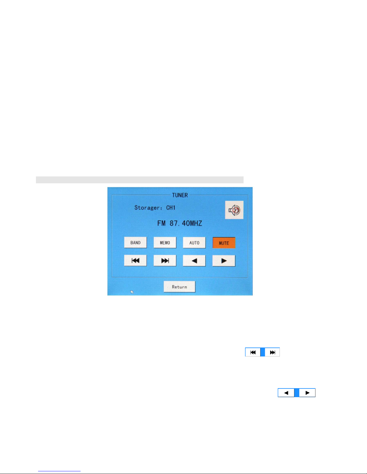
It is applicable to enter the radio play interface to select play status once “radio” audio source is
selected. As shown in the following figure, radio play operations include band switching, radio station
searching and storage as well as mute setting.
Note: Ensure correct connection of radio module on the rear panel of the machine.
① Band switching: As shown in the aforesaid figure, “BAND” on the interface is used for band switching. It is
applicable to click this button for switching between AM and FM. Frequency band of AM and FM is
522kHz-1620kHz and 87.00MHz-108.00MHz respectively.
② Radio station searching: Click “AUTO” to select radio stations before clicking forward and
backward auto searching. Searching will come to a stop once any station is discovered.
③ Station memory: Any station as searched is available for numbered memory to facilitate timing control and further
use. AM and FM are provided with 40 memory numbers respectively for storage of 40 station channels. Once any
station is searched, click “MEMO” to change the button into orange color, and then push the to
select memory number. Once corresponding memory number is selected, click “MEMO” again to change the
button into white color to complete station memory.
④ Mute: As shown in the aforesaid figure, the button will be in orange color once the “MUTE” is clicked.
Meanwhile, speaker icon at the right upper corner will be switched to the status as shown in the figure. This
(Figure3 Tuner)
Page 14
14
indicates that radio is switched to mute mode. The button will be in white color again if “MUTE” is clicked to
cancel the mute mode.
3) Zone Switch Operation
Zone switch is available for both individual and synchronous control. As shown in the main interface, only zone 1-20 are
displayed on the interface. It is necessary to use page rolling button (as shown in the following figure) for display of zone
21-40.
Main Interface
Click zoning button directly for switching operation. The button will be in white and green colors respectively when
corresponding zone is closed and opened. Furthermore, audio source for the said zone will also be displayed on the zoning
button. It is also applicable to proceed with overall synchronous operation of the zone. Operation button is as shown in the
aforesaid figure.
4) Output power source
As shown in the aforesaid figure, PWR1 and PWR 2 are control buttons for output power 1 and 2 respectively. It is
applicable to proceed with switching control of output power by clicking such buttons directly. Output power is also
available for auto timing control.
5) Programmed / manual switching
As shown in the aforesaid figure, it is applicable to click “programmed/manual control” button directly for switching
between programmed and manual modes.
Note: Be sure to set this button at preset “programmed” timing point for execution. All timing points will unavailable
for execution if such button is in “manual control” mode.
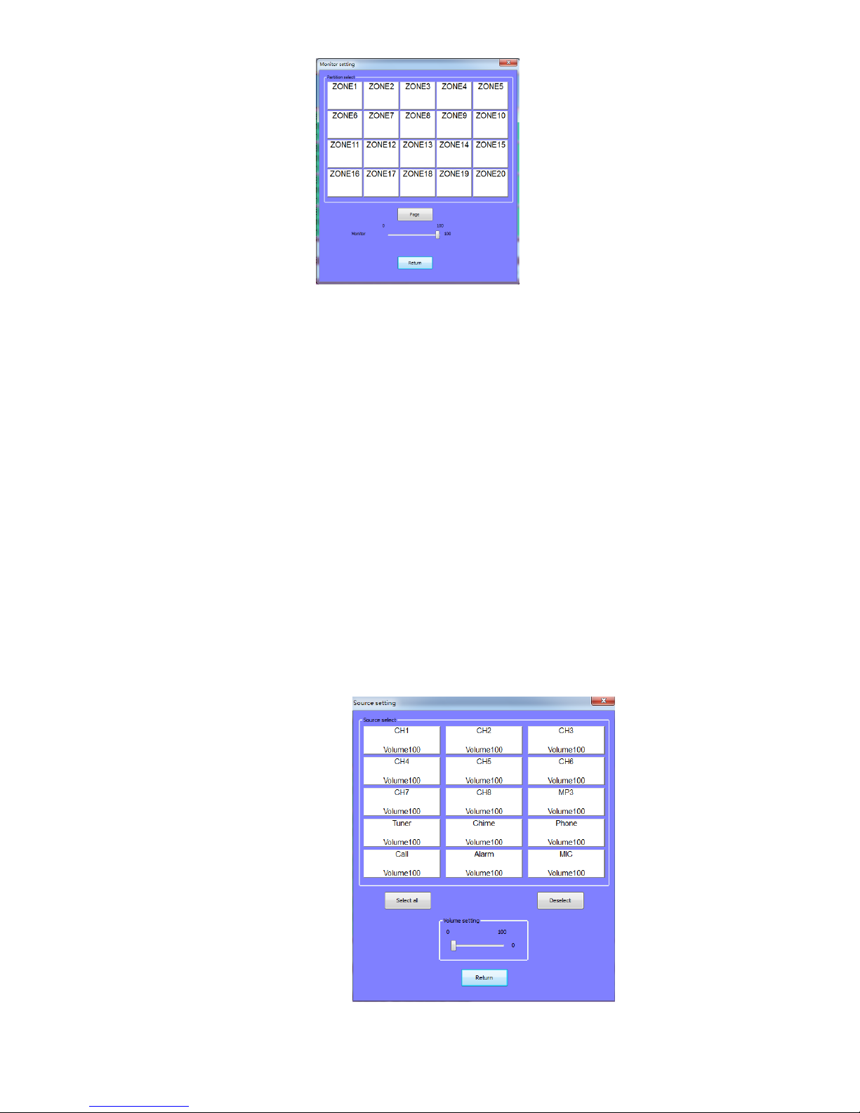
6) Monitoring Setting
This machine is available for monitoring of each zone. Click “monitoring setting” button to enter the monitoring
interface as shown in the following figure in case of operation.
Output
power
control
button
Zone
on/off
control
button
Programmed/manual control switching
button
Page 15
15
It is applicable to monitor zone status by clicking zone button on the monitoring interface directly. The button will be
in green color when the zone is under monitoring; whereas “×” before the speaker icon will be changed into “√”. Use “Page
Rolling” button to open the display interface for zone 21-4 to be monitored. After that, press zone button for monitoring.
7) Partition volume control
By using the digital volume adjusting partition volume, digital equalization settings, convenient
operation and clear, can choose a single partition volume adjustment, can also choose "select" button, all the
partition volume adjustment or cancellation of choice. First click on the main interface on the partition
volume adjustment button, enter the "partition volume adjustment" interface, the interface is as follows
(Figure 5), click on the partition operation is as follows: 1, (when the partition is selected, the button turns
green, to partition the set volume value, slide the bottom left of the left and right mouse button to adjust the
volume, the 1 District Partition volume on the automatic synchronization display adjusting the volume value,
can also be balanced set the volume. The other partition and so on, set the volume, clicks the "back" button,
exit partition volume control settings.
Figure 4 Monitoring Setting
Page 16
16
8) Sound volume
Click the source volume button on main interface , enter the audio volume control interface, the interface (Figure 7)
shows as follows, regulate the sound volume and partition the volume control setting method of the same, this is no longer
in this paper.
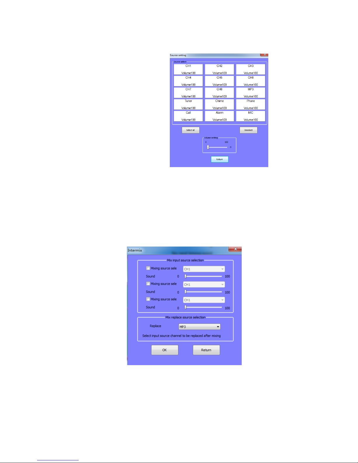
9) Mixing operation
Click on the main interface of the "mix" button, enter the mixing operation interface. The interface is as follows
(Figure 8) shows the input audio select 3 audio mixer respectively, operation setting. click on the left side of the small box,
when the small box color turns green, click on the right side of the lower triangular symbols, a total of 15 kinds of audio
input, in the drop-down box choose a source (for example the selection of source 7), mixing source 2 (selected source 5)
and mixed audio choice 3 the same operation, arbitrary selection of an audio output, namely the input source 7 and the input
source 5 at the same time, through the built-in MP3 audio output.
5.2 System Setting
Click “System Setting” on the main interface to enter system setting interface as shown in the following
figure: It is applicable to proceed with setting of overall system information on the system setting interface.
Be sure to ensure proper setting of all options on the system setting interface before play on the main
Page 17

17
interface. This aims to ensure accurate execution and operation of various system functions.
1) Timing setting
Click “Timing Setting” button to enter the timing setting interface as shown in the following figure:
This interface is for editing various functional information on timing points:
① Week selection: This operation aims to select the date of timing points. For instance, it is applicable to
select corresponding date in the block of “Monday-Friday” if timing points are to be executed from Monday to
Friday (“√” in the block represents selected date).
② Designations of timing points: Define designation for edited timing points. For instance, timing point
representing wake-up bell can be defined as “Wake-up”. Open the designation editing button board (click the
functional button of “Alteration” on the right side of timing point designation block) to enter the editing button
board interface (as shown in the following figure). After that, select Chinese or English at the bottom right corner
This item is to be selected during timing
point setting; otherwise, timing point will
Chime setting: Select chime signal.
No selection means no chime.
Figure 9 System Setting
Page 18

18
of the button board. Input timing point, and click the “Confirm” button at the bottom to complete editing, and exit
the button board.
③ Bell selection: There are 3 bell signals available for selection in the system. Click inverted triangular symbol after
the “Bell”, and select bell signal on the drop down menu. The 3 bell signals are defined as bell 1, 2 and 3
respectively. Click the selected bell for one time to display its designation.
④ Timing time: This setting aims to edit start time of timing points. It is applicable to alter the time by click black
triangular symbol beside the time block. Timing time of the system is accurate to second. Timing to the second
will not be required if not necessary.
Note: The start time of the same timing point at different dates cannot be set to the same after a day than the
previous day need to lag 1 second. For example, Monday has 7:00 for the start time of the timing point, thus
can't set the 7:00 for the starting time on Tuesday. The start time must be set to 7:01. On Wednesday at the same
time the timing of the start time is needed to set to 7:02, On Thursday and so on.
⑤ Output power supply control: “PWR1, PWR2” behind the “Timing Time” is used to control switching status of
two-route power supply on the rear control panel. Click corresponding block for one time to select required power
supply status on the drop down menu to complete setting.
⑥ Completion time: Method for setting of completion time I identical to that for start time. The only difference is that
the system has optional requirement for completion time. In other words, completion time may be required or not
required as per specific demands, which is to be defined as per timing points.
(Figure 12) Indication of Output Power Supply and Completion Time
⑦ Program selection: This operation aims to select operative audio source for timing points. Select “Program
Be sure to select English or Chinese
before input
Click to select here before
setting of completion time
Click here to select output
power supply status to
complete setting.
Figure 11 Timing point naming editor keyboard
Page 19

19
Selection” button to enter the program setting interface as shown in Figure (10), (11) and (12). One built-in timing
point is available for timed play control of built-in MP3, built-in radio and 4 external audio source
(Figure 13) Setting Audio Sources for Timing Points
As shown in Figure (13), click “Add” button to select catalog when setting built-in MP3 programs
(such as selection of “common comity”). After that, click “Next Catalog” to open the catalog, and select
songs to be played. Once completed, click the “Add” button, and designations of selected songs will appear
in the play list of “Selected Songs”. It is also applicable delete any song from the play list of “Selected
Songs”. Specific method is stated as follows: Select the song to be deleted, and click “Del” on the right side.
Select required control status among “Uncontrolled”, “Play” and “Stop” at the bottom right corner of
the interface prior to editing when setting built-in radio programs (as shown in Figure 13). Note: Be sure to
set wave band and channel after selection of play status. Channel number represents the memory number of
station as stored in the radio tuner. Radio function at corresponding timing point will be invalid if the
selected memory number is not stored with any station
Setting of external audio sources involves the following operations: Selection of audio equipment
types, control modes (play or stop) and programs. Click “Add” to add the audio source into the list of
“Controlled Equipment” once any equipment (such as holder) to be controlled by the timing point is selected.
It is also applicable to delete any uncontrolled equipment from the list (as shown in Figure 15).
Click “Return” button at the bottom to exit the audio source setting interface once all items are set.
Set wave band and channel after.
selection of play
Select the directory from the top box
and click here to open the directory and
select tracks
Page 20

20
⑧
Zone selection: Click “Zone Selection” button on the timing setting interface to enter the zone selection interface as shown
in the following figure (Figure 16).
Any timing point in this system can control play status of 6 audio sources. The 6 audio sources are
available for free selection in the corresponding zone. In other words, all zones at one timing point can play
different programs.
Firstly, select audio sources to be distributed to corresponding zone in case of setting. For instance, it is
necessary to select “external radio” audio source, and click buttons in zone 1-10 if external radio is to be
distributed to zone 1-10. Under such circumstance, corresponding button will be in green color to display
“external radio”. If all audio sources subjecting to timing control are to be distributed to corresponding
timing control zone, just click “Back” to exit the interface to complete timing setting of corresponding zone .
⑨ Once items for timing points are set, click “Add” to add such items into the timing list.
⑩ Deletion of timing points: Timing points can be deleted by clicking individual and whole deletion buttons. “Del”
aims to delete certain selected timing point in the timing list; whereas “Delete All” is expected to delete all timing
points.
⑪ Saving of timing points: Click “Add” to save one timing point as edited in the system. After that, click “Back” to
Click this button to add equipment as set
(Figure 15) Audio Sources for Timing Points
(Figure16) Select partition
Add external device
Device type
Control type
Playing program
External source
Controlled
Add
Delete
Delete all
Device Program other
Socket 1
Page 21

21
exit the timing point setting interface.
2) Timing scheme
In the "system settings" interface, click the "timing scheme" button to pop up the timing scheme
selection interface, interface as shown in the following figure (Figure 17) .Here chose to determine a
timing scheme and programming from time to time in editing the timing point will be automatically
saved in the set of timing scheme. In time before programming, it is recommended to here choice timing
schemes, so according to the need to edit out 5 sets of timing scheme, convenient later call. In this
interface, to the current 5 sets of timing scheme for renaming, save scheme as shown in Figure 18,
figure 19
(Figure 18) Select Partition
To rename the timing scheme, click "Rename" enter (Figure 18) timing scheme named interface, the
public has 5 sets of programs, such as to rename the first set of options, click behind the "modify" button,
enter edit interface, keyboard, as shown in (Figure 19), input file name, and click on the bottom of the OK
(Figure17) Timing scheme
(Figure 18) Selecting Partition
The current timing
scheme
Scheme 1
Ok
Cancel
Rename
Save it
Return
Scheme 1
Scheme 2
Scheme 3
Scheme 4
Scheme 5
Timing Scheme Rename
Scheme 1
Scheme 2
Scheme 3
Scheme 4
Scheme 5
Modify
Modify
Modify
Modify
Modify
Ok
Cancel
Return
Page 22

22
button, can complete the rename edit and exit the keyboard and other operations.
3) Program Setting
Click “Program Setting” on the “System Setting” interface to enter the setting interface as shown in the
following figure (Figure 20):
Program Setting” for system setting aims to edit music library of built-in MP3, including browse, copy
and deletion of songs. As shown in the aforesaid figure, once certain catalog in the catalog block on the right
side is selected; all songs in it will be displayed in the central program block. Once programs in such block
are selected, it will be applicable to proceed with deletion operation by using deletion button at the bottom
of the interface.
Block on the right side of the interface aims to display programs in the USB on the front panel. Once
song designations are directly displayed in this block, it will be applicable to select relevant songs. After that,
(Figure 19) keyboard editing interface
Sound source 1
Backspace
Delete
Ok
Cancel
Page 23

23
click “Individual Copy” button below the block to copy selected songs into the machine. In the event that
catalog is displayed in the block below “USB Device”, just select certain catalog, and click “Next Catalog”
below the block to enter the play list before copy programs.
Tips: when insert the U disk to the device, waiting for 10 seconds until the disk program can
display in the directory column. There are some individual U disk can’t fine the files. So users can to
return to the main interface of the system, re-entering the track settings interface can find U disk file.
If catalog is displayed in the block below “USB Device”, just select this catalog, and click “Copy
all” to copy all songs in this catalog into the machine.
Note: As music library of the system is only provided with one catalog, any song under the catalog additionally
established is unavailable for play. Therefore, never copy songs to the system music library when copying programs.
4) Alarm Setting
Click “Alarm Setting” button on the “System Setting” interface to enter alarm setting interface as
shown in the following figure (Figure 17). It is applicable to set alarm zone linkage, alarm audio source and
alarm triggering level on this interface.
Be sure to properly set “Alarm Audio Source Setting” and “Alarm Level” below this interface in case
of setting. After that, select one certain alarm channel (such as CHN1) in the “Alarm Channel” block on the
left side. Once completed, select alarm zone to be triggered by CH1 in the “Triggering Zone Setting” on the
right side. It is applicable to select single or all zones or cancel the selection.
If “Alarm Time” is not selected, the system will initiate internal alarm whistle as alarm signal when
external alarm audio source is actuated for alarm. If such option is selected, just use externally input alarm
signal in priority instead of using internal alarm whistle in case of alarm. Make sure that external alarm
equipment has been properly connected under such circumstance.
Page 24

24
5) Wireless Process Setting
Click “Wireless Process Setting” button on “System Setting” interface to enter wireless process setting interface as
shown in the following figure (Figure 16). This system can be controlled with wireless controller in the control mode
identical to that for timing points. Remote control distance of wireless remote controller ranges from 100m to 1000m as per
different environments. Be sure to properly set certain functional operation of certain button on the wireless remote
controller for control of this system in advance. Thus, once this button is pressed, the system will automatically execute
preset functional operation.
Select certain remote control number (such as remote control number 1) among the “process serial numbers” on the left
side in case of setting. After that, set control items in the functional setting block on the right side. For instance, if remote
control number 1 is to be selected to control play of audio source :CH1” in zone 1-10, just click “Zone Selection” button to
enter zone selection interface after selection of “remote control number 1”. Distribute audio source “CH1” to zone 1-10 as
per audio source distribution mode on the interface before exiting the interface. If “remote control number 1” is requested to
control play status of audio source, just enter the “Audio Source Setting” interface to proceed with various settings of audio
source. Setting mode is identical to that for setting of audio sources for timing points. “Remote Control Number 1” is also
available for simultaneous control of status of output power supply and bell.
Prompt: One button of wireless remote controller is capable of controlling one or numerous functions of this system.
However, all controls should be set here in advance. Operation for selection of zones and programs is identical to that for
timing points, which shall not be described herein.
(Figure 22)Wireless group setting
6) Telephone Setting
Click “Telephone Setting” button on the “System Setting” interface to enter telephone setting interface as shown in the
Page 25

25
following figure (Figure 23).
The user can set password at discretion on the telephone setting interface. If it is necessary to select use of password, just
input 4-digit password in the password input block. In this way, it will be applicable to input password t for calling or
paging in case of incoming call.
Click “Grouped Paging” in the “Paging Setting” block to proceed with grouping for paging zones as shown in the
following figure (Figure 24):
Select one certain grouping number below the “Grouped Setting” blocks before click the zone on
the right side in case of grouped paging. This zone is to be incorporated into the selected group. One group
may include numerous or all zones. This system is available for setting of 10 groups. It is applicable to
select grouping number as per voice prompt in case of telephone paging. The system is capable of sending
telephone paging to numerous zones simultaneously.
7) Nomination of Audio Sources
(Figure 25) Phone Setting
(Figure 24) Telephone Group
Page 26

26
Click “Audio Source Setting” on the “System Setting” interface to enter the audio source setting
interface as shown in the following figure (Figure 25):
It is applicable to alter or nominate designation of each audio source on this interface. Click the block displaying
designation of audio source to select certain audio source (such as CH2), and then click “Alteration” after it to open the
input button board. Input designation of the audio source on the button board, and click “Confirm” button to complete
nomination of audio source. Once completed, push the “Confirm” button again to return to the system setting interface.
8) Zone Nomination Setting
Click “Zone Nomination Setting” button on the “System Setting” interface to enter zone nomination interface as shown in
the following (figure26)
(Figure25) Nomination of Audio Sources
(Figure 26) Zone Nomination Setting
Page 27

27
It is applicable to edit a designation for each zone on this setting interface so as to facilitate edit and
management of zones in this function. Click the zone for designation editing to enter designation editing
button board in case of setting. Input zone designation on the button board, and click “Confirm” button to
exit the button board to complete nomination of the zone.
9) IP address Setting
As following(Figure 27),in the "system setting", click "interface IP address settings" button, enter the
IP address setting interface, you can modify the IP address, sub-net mask, the gateway, remote control port.
When you want to set in operation, (for example, to modify the IP address) ,click the "Edit" button on its
back to enter the keyboard input edit interface to modify the IP address, and then click the OK button on the
bottom to complete the IP address change. And exit the editor keyboard interface, other modifications are of
the same operation set.
10) Network Timing
In the system settings interface, click on the "network timing" button to enter the interface as following (Figure 28 ),
choose “whether to start using the network timing ”button, set the machine's IP address and IP services in the same segment.
If you start the network
timing, please check
here.
Page 28

28
11) Language selection
English and Chinese can be selected here!
13)Machine code
12) Configuration operation
This setting, configuration file are exported to the U disk, import the
configuration file to the system and software upgrades, before the operation of this
item, insert the U disk.
14) Partition volume / volume source
In system settings interface click “partition volume and audio volume "button to
enter the partition volume and audio volume interface and have the same in here the
partition volume and audio volume mode of operation with the main interface
partition volume mode of operation, the operation please reference on the main
interface of the partition volume" that part. This will not repeat them.
15) Recording operation
Chinese
English
Ok
Cancel
Page 29

29
Click the recording operation button on the interface of system settings, entering
the following (Figure 29) shows: click on the "recording" button will see “preparing
to record, please wait for a moment” .when the recording is finished, click the "stop"
button. The recording setup interface will display the recorded file .When recording
for the second time, modify the file name first. Selected the file in the box , click the
"delete" button can be completed to delete, select the same block in the file, click the
"audition" button, you can play. Before the operation, please pay attention to the
interface description!
15) System Setting
At the interface you can set the system time, screen protection status and touch screen
calibration. The interface is shown below (Figure 30).
(Figure 30) System setting Interface
Page 30

30
To regulate the screen on the touch screen settings, click the “re-regulate” screen
will restart the system into the touch screen calibration; select the items on the screen
protection settings, after a period of time without any operation, the screen does not
display or change any screen protection, until the touch panel on the screen with touch
when the screen display again. The protection time can be set, optional period in 1 to
30 minutes. You can also not set the screen saver, this screen from start up to shut
down in the open state.
Check “enable the phone to electric tone "; when there is a telephone coming,
there is a voice prompt, the same as wireless key tone. When not checked, no sound.
When setting the system time, please according to the current clock, which is
related to the timing of the execution timing .It can be accurate to second. So please
pay attention to set the second. When finishing the setting of the system time, press
OK button to finish, click the return button to exit the system settings.
Page 31

31
6、Other Functions
6.1 Warning
This machine aims to send warnings to individual or partial or all zones based on
the input warning signals. Prerequisite for receiving external warning signals by the
machine is stated as follows: It is a must to set warning level properly in “Warning
Setting” block on “System Setting” interface (refer to System Setting).
The system will send warning signal to one zone in advance when it is necessary
to give warnings to individual or partial zones. After that, this zone will be linked up
with adjacent zones to further send warning signals. This machine can also send
warning signals to all zones through total warning button on the front panel (refer to
Description of Front Panel). When total warning button is used to send warnings to all
zones, it will be impossible to operate switches, and distribute audio sources until the
total warning button ejects. Priority of warnings to individual or partial or all zones is
next to signals from aviation microphone. In other words, no action is able to
terminate or cover warning action except for signals from aviation microphone.
2. Paging
This system can send paging to corresponding zone through remote pager or aviation
microphone on the front panel.
1)Paging with aviation microphone: Signals from aviation microphone have the highest
priority, which can cover all other signals. Be sure to properly connect the microphone, and push
the paging button before clicking the target zone for paging. When aviation microphone is used
for paging, certain zone playing warning signals will be automatically switched to aviation paging
status. Except for the zone subjecting warning, status of other zones is unavailable for auto
switching, which requires manual clicking. Once paging by aviation microphone is completed, all
paged zones will be switched to the status before paging automatically, including warning.
2)Paging through remote pager: Connect remote pager (refer to Introduction to Rear Panel),
Page 32

32
and select target zone on the remote pager to send remote paging to corresponding zone in this
system. With regard to method for paging with remote pager, please refer to Operation
Instructions for Remote Pager. Remote paging signals have level 3 priority, which can cover
signals of telephone paging and background audio source.
3)Telephone paging: It is necessary to proceed with setting of relevant issues concerning
telephone paging in “Telephone setting” block on “System Setting” interface before telephone
paging, including grouping and password. For setting methods, please refer to Telephone Setting.
Telephones on this machine fall into 10 groups. It is applicable to input grouping number directly
on the telephone set as per voice prompt in case of telephone paging. For instance, press figure
“8” on the telephone set and “#” for paging the 8th group. Be sure to input password as set during
“Telephone Setting” before further inputting the target group for paging. Telephone paging has
level 4 priority, of which signals can cover signals of background music.
3. Priority Sequence
Priority level of this system is in the following sequence: aviation
microphone---warning---remote paging---telephone paging---background music.
Signals of higher priority will cover lower ones for prior output. Signals of lower
priority will be automatically recovered once those of higher priority are sent.
4. Calibration of Touch Screen
Touch point on the touch screen will be unavailable for accurate shift to the
operating option due to rise in temperature or other factors after the machine is
operated for a certain period of time. It is applicable to calibrate the touch screen with
the following methods under such circumstance.
1)Touch “System Setting” option on the main interface to enter the system
setting interface. Touch “System Setting” option on the option interface to enter the
interface of screen calibration and time setting.
2)Touch the “Touch Screen Re-calibration” button on this interface to restart the
system, and enter the screen calibration interface (as shown in the following figure).
Page 33

33
3)Click the center of cross icon with nib on the screen calibration interface (note:
be sure to click the center).
4)Proceed with aforesaid calibration at four corners and center of the screen.
Otherwise, it will be unable to shift the cursor to the designated option during
operation. Under such circumstance, it is applicable to connect USB mouse to restart
screen calibration on the screen calibration interface.
Screen Calibration and Time Setting Interface
Note: It is only applicable to use nib to click the center of cross icon during screen
calibration. Never touch the touch screen with body or other objects. Otherwise, it may
result in failed screen calibration. Under such circumstance, it will be impossible to use
cursor to select the designated option in the system.
Click the central of
cross icon with nib
Touch screen calibration interface
Page 34

34
Packing list
NO.
List
Quantity
1
MAG2140II(MAG2120II)
1
2
Touch pen
1
3
MP-P National standard power line
1
4
FM antenna
1
5
AM antenna and antenna pedestal
1
6
Hardware MP9908 flat cover
1
7
SY564 line(Crystal serial port)
1
8
SY542 audio line
2
9
Wireless receiving antenna
1
10
12 remote wireless remote control
1
11
M5×19 cup head cross screw
4
12
2 meters telephone line with crystal head
1
13
White washer
4
14
CB100 Microphone(with plug)
1
15
Certificate
1
16
Guarantee Card
1
17
Manual
1
Page 35

35
Specifications
Any alteration to specifications shall not be notified otherwise.
Model
MAG2120II
MAG2140II
No. of control zone
20
40
Display
5.6-inch color screen
Control mode
Touch screen/remote control/wireless control
Input sensitivity
250mV(±25mV)
Output
1V(0dBV)
Built-in audio source
Radio, MP3
MP3
Frequency
response
20Hz-20kHz
SNR
85dB
Dynamic
range
90dB
Harmonic
distortion
0.05%
Radio
AM
Sensitivity
52dBu
Receiving range
522kHz-1620kHz
Transmission band
6kHz
SNR
35dB
FM
Sensitivity
26dBu
Receiving range
87.0MHz-108.0MHz
Transmission band
15kHz
SNR
75dB
Wireless control
12 unit with control distance within 100-1000m
Frequency response
20Hz-20kHz(±3dB)(individual zone)
SNR
85dB
Cross talk
70dB
Warning mode selection
Low level is 0V; high level is 5V~24V
Timed power output
PWR1
AC220V/50Hz/500W
PWR2
AC220V/50Hz/500W
Fuse
Local protection
F1AL
Power source protection
F10AL
Power source
AC220V(±10%)/50Hz
Gross power
22W
Packing size (mm)
(L×W×H)555×460×235
Machine dimension (mm)
(L×W×H)484×360×132
Gross weight
11.8kg
12.3kg
Net weight
9.2kg
9.6kg
Page 36

36
1 Safety Precautions
Do not plug the power plug of the device into the power grid without
connecting the system line.
Make sure the voltage input equipment and the equipment
requirements are exactly the same, or risk burning equipment.
The machine has the dangerous voltage, the voltage is sufficient to
cause an electric shock, do not open by yourself, so as to avoid the
risk of electric shock.
When the power of the equipment switch in the "off" state, the
machine did not appear to be associated with power grid disconnected
completely, for the sake of safety, please will the power line plug out
of the socket when you do not use it.
Do not place equipment placed with cold or hot.
Make sure that the equipment working environment in good
ventilation, in order to avoid the damage to the machine caused by the
work of fever, high temperature.
Pull out the power plug when in the cloudy wet weather or do not use
the machine for a period of time.
Take down or reset any parts of the equipment, cut off or re-connect
any electrical plug, or before other connections, be sure to pull out the
power plug to ensure the device completely separate from the grid.
In order to avoid the accident or aggravate the extend of the damage,
When the equipment is in trouble; do not open the enclosure privately
without any professional permission.
Don't put any corrosive chemicals on or near the top of the
equipment.
Page 37

37
2. Precautions for After-sale Services
Our company will provide three-year free guarantee (including free replacement of
parts) for any quality problem as occurred during regulated installation and normal
operation as per operation instructions from the date of purchase.
Any user enjoying the free guarantee is requested to present receipt of the warranty
card and invoice.
The following cases are not covered by free guarantee:
(1) Damages to products due to incorrect installation, operation or handling;
(2) Damages to products by any abnormality (such as over-voltage or extremely high
ambient humidity);
(3) Damage as incurred by such incidents as natural and man-made disasters to
products.
(4) Product number has been changed, altered or deleted;
(5) The product was once repaired or refitted by personnel not authorized by the
company;
Please properly keep the operation instructions and warranty card.
With regard to issues or precautions not mentioned in the operation instructions, please
contact corresponding distributor or visit official site of the
company---http://www.dsppatech.com
Please contact service personnel of our company (or distributor) for processing in case
of fault during guarantee period. Our company shall not guarantee any damage as
incurred by unauthorized dis-assembly or repair by other technicians.
Page 38

38
ATTACHMENT
Notes on the application of U disk file format:
1. Due to the rapid development of the U disk and various type of memory
and the market is complex and chaos, this product may not be compatible with all
brands, models and specifications of the U disk on the market. In order to ensure
read U disk information normally, it is recommended to use 1g-16g capacity of
the U disk (e.g. Kingston) 1g-16g and regular brand authentic U disk (such as the
Taiwan Power Lenovo/ / flash DI / Kingston etc.) on the machine. This system
only supports MP3 file format, the highest rate of 320KBPS, the other format of
the audio file cannot be played, if you find that some songs cannot play, you can
see if the song is in line with the requirements.
2. Support FAT32 and VFAT file system.
3. In order to improve the speed of operation and optimize management, it is
recommended that you use the U disk only to retain MP3 songs, it is best not to
store other files, so as to improve access speed and easy to edit the timing point.
4. Please do not save a song directly into the U disk root, please create a
folder in the root directory when copy the program by U disk, and then copy the
songs to the new folder. This system in the root directory of up to 99 level
directory, each directory up to store 99 songs.
Note: Do not crate new sub directory under the first level directory
otherwise the songs will not be able to read. You can use the following three ways to
store
1. Songs can be stored in the first level directory, the advantages is the song
can be stored classified and can be stored up to 99 x 99 songs.
USB
Document
Document
01. MP3
99. MP3
02. MP3
01. MP3
99. MP3
02. MP3
Page 39

39
Remote Control (Optional)
1)Installation of Remote Control Computer Software
LAN interface can be connected with computers to realize remote control of the host computer
through control software (realize auto play of fixed programs at fixed time and place). (Such
function is to be realized by remote control software separately purchased).
Any system installed with remote control software is to be attached with a remote control
software installing CD at the time of delivery. Insert this CD into the CD-ROM to install the
software in the computer according to prompts. Installation procedures are stated as follows:
Initiate installation program to enter the interface as shown in the following figure:
Click “Next” on this interface to enter the follow-up installation interface.
Page 40

40
Click “Finish” and it the
installation will be done
Page 41

41
2. Computer remote control
After finishing the installation of remote software with computer
controller, it will generate a shortcut icon on the desktop; double click the
icon to enter the next one interface:
2.1 Remote Control Operation
System control interface as shown in the aforesaid figure can be used for setting of audio
matrix to distribute 10 audio sources to 40 zones (20 zones for MAG2120). Operation methods for
audio source distributed to each zone are identical to that for the host computer, which will not be
described herein.
Page 42

42
2.2 Timing Point Setting and Synchronization
1. As shown in the aforesaid figure, all timing points as edited are displayed in the list. Click
options in the list for setting.
2.
3.
Help information will be displayed automatically when the mouse stops at aforesaid buttons.
4. Add: Add one timing point for auto addition into the list.
5. Del: Delete one selected timing point in the aforesaid list.
6.
Delete All: Delete all timing points in the list. It is applicable to proceed with
backup of current timing point by clicking “Save As” before deletion.
7. Ordering: It aims to realize precedence ordering of edited timing points in proper
sequence as per commencement time.
8.
“Open”, “Save” and “Save As”: The three buttons are used for backup and recovery of edited
Click timing point, and input password to enter the timing
edit interface
Mark in red represent timing
point edit zone
Page 43

43
timing points. Shift the mouse to such button to display detailed help information.
9. Download Timing Points: Download timing points on the broadcasting
mainframe to current list.
10. Synchronization to broadcast: Synchronize edited timing points to broadcasting
mainframe.
2.3 Resources Nomination
Click “Resources Nomination”, and input
correct password to enter the setting interface.
Save current
nomination program as
file
Synchronize edited audio
sources to broadcasting
mainframe.
Zone nomination is identical to that for
audio sources
Page 44

44
2.4 Wireless Grouping Setting
As indicated by the icon, wireless grouping falls into 3 steps:
① Select remote control key for setting.
② Display selected information on remote control key for direct setting on such interfaces.
③ Use such buttons to realize such functions as backup, recovery and synchronization once
all wireless groups are edited.
Click here to do the wireless
grouping setting
Page 45

45
2.5 Telephone Setting
As shown in the figure:
○
1 This zone is for telephone grouping setting. Click grouping list to select corresponding group
for setting, and then click zone list setting to see if it has been opened.
○
2 This zone is for setting of telephone password. It is applicable to set password and
forbidden/invocation password.
○
3 This zone is for saving, open and synchronization of edited settings to the mainframe. Click
such buttons to realize this function.
Click “Telephone
Setting”, and input
correct password to
Page 46

46
2.6 program management
Operation instructions:
Firstly, double-click in the regional radio host program list to select the programs
need to modify, and then select the upload songs in the right area of the local host
directory tree, after selection, click "start copy" button (or direct the hook selected file
drag and drop it into the host broadcasting program list) to begin copying files and
please do not carry out other operations during the copying period. Program after
modification please click region 3 updates the host "button can be completed.
Note: if you encounter the progress bar does not scroll during the copying
period, please try to click on the "re-connection" button to re connect.
3. Remote Control Software for Android
System
3.1. Installation
3.1.1 Installation File
Any user having purchased micro intelligent remote control software can find the
file entitled “micro intelligent mobile phone installation pack.apk” in the CD (“micro
intelligent tablet installation pack.apk for Android system tablet). This file can be
uploaded to the Android mobile phone (tablet) through USB or in other modes.
1
Page 47

47
3.1.2 System Requirements
As tested, the software can support mobile phone system (tablet above version
3.0) above Android 2.1. Please do not hesitate to contact use, and indicate mobile
phone model and system version if your mobile phone (tablet) is not compatible with
this software.
3.1.3 Installation Procedures
Open the installation file entitled “micro intelligent mobile phone installation pack.apk” on
the mobile phone (tablet) to enter the following interface. Click installation button for installation.
Be sure to click “Open” button after network setting upon completion of installation.
3.2. Network Setting
It is applicable to control micro intelligent mainframe through WIFI and 3G network. As
requested by 3G network, any user should have an IP for static public network as distributed by
network supplier. However, dynamically distributed IP such as ADSL is not applicable. Please
contact relevant network administrators.
3.2.1 WIFI Control
3.2.1.1 Equipment Requirements
Android mobile phone (Android system tablet), micro intelligent mainframe and
wireless router.
Page 48

48
3.2.1.2 Setting Methods
(1)Refer to operation instructions for micro intelligent mainframe, and click IP setting
button on the system setting interface to enter mainframe IP address setting interface. Properly set
IP address and remote control port of micro intelligent mainframe. For instance, IP address and
port of the mainframe can be set as 192.168.1.211 and 8001 respectively.
(2)Connect mainframe with network of wireless router.
(3)Open WIFI on the mobile phone (tablet), and make sure that IP addresses of the mobile
phone and micro intelligent mainframe are on the same network section. For instance, mobile
phone can be set as 192.168.1. 2.
3. Android Mobile Phone Software/Mobile
phone software
3.1 Installment
3.1.1 Install files:
After the user buys the micro intelligent remote control software, find a file named "micro
intelligent installation package.apk" in the disc. Uploaded to the Android phone (tablet) via USB
or other means.
3.1.2 System requirements
After testing, the software supports more than Android2.1 version of the mobile phone
system (version 3.0 and above the tablet), if the mobile phone users (flat) cannot install this
software, please contact us in a timely manner, and explain the phone model and system version.
3.1.3 Installation steps
Open the "micro intelligent installation package.Apk" installation file, the following interface
will display, click the Install button to install, after the installation is completed, do not click on
the open button, and then set up a good network.
Page 49

49
3.2 Network Setting
3.2.1 WIFI Control
(1) equipment requirements
Android mobile phone (Android system), micro intelligent host, wireless router.
(2) Setting method
① Read the micro smart host instructions for reference click the IP settings
button in the system settings, enter the host IP address settings interface to
set micro intelligent host IP address and remote control port. Such as: set the host IP
address for 192.168.199.251 port: 8001.
② Connect the host to the network in the wireless router.
③ Open the WiFi on mobile phone (tablet), ensure that the IP address of the
mobile IP address and micro intelligent host in the same segment. Such as: set the
phone to 192.168.199.
3.3 Android tablet / mobile phone software instructions
Enter the control interface as shown in the following figure following successful
operation of the software:
1) Network Setting
After the successful installment of the software, it requires registration when it is
used for the first time after connection. So it is in offline state before the connection is
Page 50

50
not registered.
Input the serial number in the sequence number column as shown below, and
then click the "register" button. The serial number can be obtained on the CD or the
host machine.
Input the IP address in the IP address column (input he host's IP address), the
port number to be consistent with the control port number of the host, click on the
"registration" button, the input is complete.
Click on "network settings" function module, when the network is not connected,
interface display offline, showing as follows. At this time the "offline" button can
move in any position, when the registration code and IP address and port number
input completed, click "connect" button to connect to the network, after a successful
connection, as follows the right edge of the chart shows, it will display connect to the
network successfully.
Switch to the
Serial
IP
Port
This button can
move to any
position.
Page 51

51
2) Remote Control
Click setting option for
switch over to different
functional modules.
Click this button to
select audio
Power on/off
button
Zone full open/close
controller
Manual and
program
Zone control: Click the
button to load selected
audio source at the
designated zone.
Page 52

52
3) Nomination of Audio Sources
4) Partition volume
Click here to
select audio
Modify the source name and
press "confirm" button
Synchronize the modified audio
source to broadcast
Click the selected partition
name
Click the confirm button after
modifying the partition name.
Synchronize the modified partition list
to broadcast.
Click to select the
partition
Adjust the volume
Adjust the partition
volume balance
Click the “submit”
button after setting.
Page 53

53
5) Audio Volume
Select the
audio
Adjust the
volume
“Select all” button to
select the audio source
 Loading...