

Page 1
1
Intelligent PA series
Amplifier MAG1306
MAG1312
MAG1325
MAG1335
Before operating, please read this manual carefully.
FEATURES
l Dual channel amplifier, individual volume and tone control for each channel.
l 200V/100V/70V rated power output.
l Clear LED display of operation status, multifunctional protection.
l With priority input (available in short-circuit); 3-wire mode output, simple
wiring system
l Exchange control signal and status information with MAG Host (choose and buy)
l Built-in voice message or siren modules for priority input (choose and buy)
l
OWNER’S MANUAL
Page 2
2
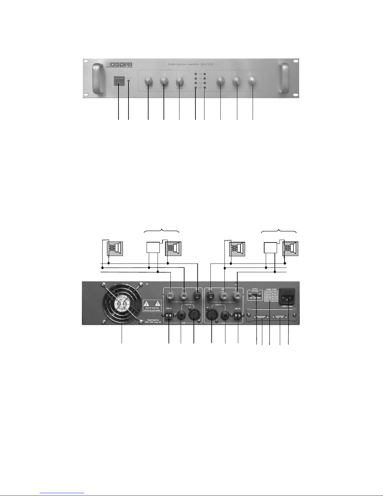
Front Panel
1. Power Switch
2. Power Indicator
3. Channel A Bass Control
4. Channel A Treble Control
5. Channel A Volume Control
6. Channel A Status Indicator (from the top down)
open circuit (available in communication),
Clip, Signal, Protection
7. Channel B Status Indicator (same with Channel
A’S)
8. Channel B Bass Control
9. Channel B Treble Control
10. Channel B Volume Control
Rear Panel and Connections
1. Channel B Output Common
2. Channel B Output HOT
3. Channel B Output R Terminal
4. Channel A Output Common(COM)
5. Channel A Output HOT(HOT)
6. Channel A Output R Terminal
7. Outtake
8. Channel B EMC IN Terminal(Available In
Short-Circuit)
9. Channel B Audio Input(TRA)
10. Channel B Audio Input(XLR)
11. Channel A Audio Input(XLR)
12. Channel A Audio Input(TRA)
13. Channel A Emc In Terminal(Available In
Short-Circuit)
14. Output Voltage Switch
15. Main Communication Interface(Optional)
16. Fuse Table
17. Communication Interface(Optional)
18 Power Supply Input(Including M/S Fuse)
1 2
3 4 5 6 7
8 9 10
1
2
3
4
5
6
7 8 9 10 11 12 13 14 1516 17 18
speakers
speaker
LINK REMOTE IN
SP
HOT R
speaker
Speaker with control
Volume control
SP
HOT R
speaker
Speaker with control
Volume control
Page 3

3
OPERATING PRECAUTIONS
l Make sure the AC supply voltage is correct, it means the AC supply voltage must be as the
same as that printed on the rear panel of the amplifier. Damage caused by connecting the
amplifier to improper AC supply voltage is not covered by the three-year warranty.
l Make sure the power switch is off before making any input or output connections.
l To prevent speaker damage, it is always a good idea to turn the attenuator to minimum
before turn-on the amplifier if there is a high level signal at its input terminal.
l The protection light on while operation means faults (e.g. overload or short-circuit)
happening. The power should be cut off immediately and should not be turn on before
correcting the faults.
l Before turn on the device, using OUTPUT VOLTAGE SWITCH to set up the output voltage
value which matches the rated voltage of connecting speakers. The switch cannot be moved
during the operation.
Input Connections
Audio input connections are made via either the 3-pin
XLR-type connectors (Figure 1) or 6.3 mm sockets on
the rear panel.
EMC IN terminal only can receive the short-circuit signal which is compatible with DSPPA series
products.
Main Communication Interface can link with MAG peripheral control interface.
Communication Interface linking with Main Communication Interface of another amplifier to
make multiple device linkage.
Output Connections
l Output terminals are on the rear panel. Speakers can be connected using banana plugs or
spade lugs. Speakers without volume controller should be connected with COM and HOT
terminals directly using broadcast line. Speakers with volume controller should be connected
with this amplifier’s COM terminal and volume controller’s SP terminal. Volume controller’s
SP terminal R terminal and HOT terminal should be connected with the same terminals on
this amplifier. (Please refer to Rear Panel and Connections diagram)
Ground(Ring
)
Signal
(
Hot
)
1
2 3
Figure1 3-pin XLR-type
connectors
Page 4

4
l The connecting speakers should have transformer inside. The total power value of connecting
speakers should not more than this amplifier’s rated power.
l All connecting speakers should have transformers inside. The total power value should not
exceed the amplifier’s rated power value.
Specifications
Model MAG1306 MAG1312 MAG1325 MAG1335
Rated power 60W 120W 250W 350W
Input sensitivity
0dB
EIN
- 80dB(A-weighting)
Output regulation
Less than 3 dB, from off-load to full load
Input CMRR
> 90dB.
Frequency
Response
80Hz~15kHz ±3dB
100Hz
±10dB
Tone
10kHz
±10dB
THD
<0.5 %, @ 1/3 rated power, 1kHz
Cooling
DC Fan for cooling
Indicator
“power”, “clip”, “signal”, and “ protection” LEDs.
Protection
Power turn on-turn off,
High temperature, DC voltage & Output Circuit Shorting.
Power
Requirement
AC220~240V / 50~60Hz
Power
Consumption
100W 200W 400W 600W
Dimensions 88×483×443mm
Gross Weight
18 Kg 21 Kg 25 Kg 27 Kg
Net Weight
17 Kg 20 Kg 24 Kg 26 Kg
Specifications are subject to change without notice
CAUTION
● When the “Power switcher” is off, please pull out the power cord from the socket.
● Please keep the equipment out of water.
● To reduce the risk of electric shock, do not remove the cover.
● No user parts inside. Refer servicing to qualified service personnel.
GUANGZHOU DSPPA AUDIO CO., LTD.
 Loading...