

Page 1
1
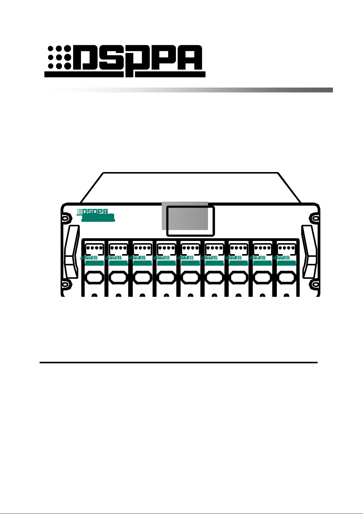
Public Address Amplifier 8M/S lntelligent PA Amplifier DA8250
PWR PROT
STAU S
SIG CLIP PWR P ROT
STAU S
SIG CLIP PWR PROT
STAU S
SIG CLIP P WR PROT
STAU S
SIG CLIP PWR PROT
STAU S
SIG CLIP PWR P ROT
STAU S
SIG CLIP PWR P ROT
STAU S
SIG CLIP P WR PROT
STAU S
SIG CLIP PWR PROT
STAU S
SIG CLIP
M-250 M-250 M-250 M-250 M-250 M-250 M-250 M-250 M-250
Public Address System 2
3
M\S Amplifier 4
DA8250 5
6
7
8
9
10
12
13
14
15
16
User's Manual 17
18
Welcome to use DSPPA public address system. For the better use of this product, please read this instruction 19
carefully prior to use. 20
21
22
23
24
25
26
27
11
Guangzhou DSPPA Audio Co., Ltd 28
http://www.dsppatech.com 29
- 1 -
Page 2

M/S Amplifier
此页留空供用户记事 1
- 2 -
Page 3

About Operation Instruction
This operation instruction shall come into effect on the date on which the development of
M/S power amplifier DA8250 equipment is completed. The operation instruction contains
the systematic introduction to M/S power amplifier DA8250 equipment, precautions for
use, instruction to connection of system, and instruction to operation of product, and so
on. The user shall read this operation instruction carefully prior to connection, installation
and use, and shall operate in accordance with the instructions herein.
The attention must be paid to the instructions with such identification on the back panel of the
machine. Please use or operation the machine following such instruction.
Please keep this operation instruction for the checking in the future.
1
2
3
5
6
7
8
9
10
4
11
DA—V0.2 12
Version: 2018-4-20 13
14
15
16
17
1
Page 4
M/S Amplifier
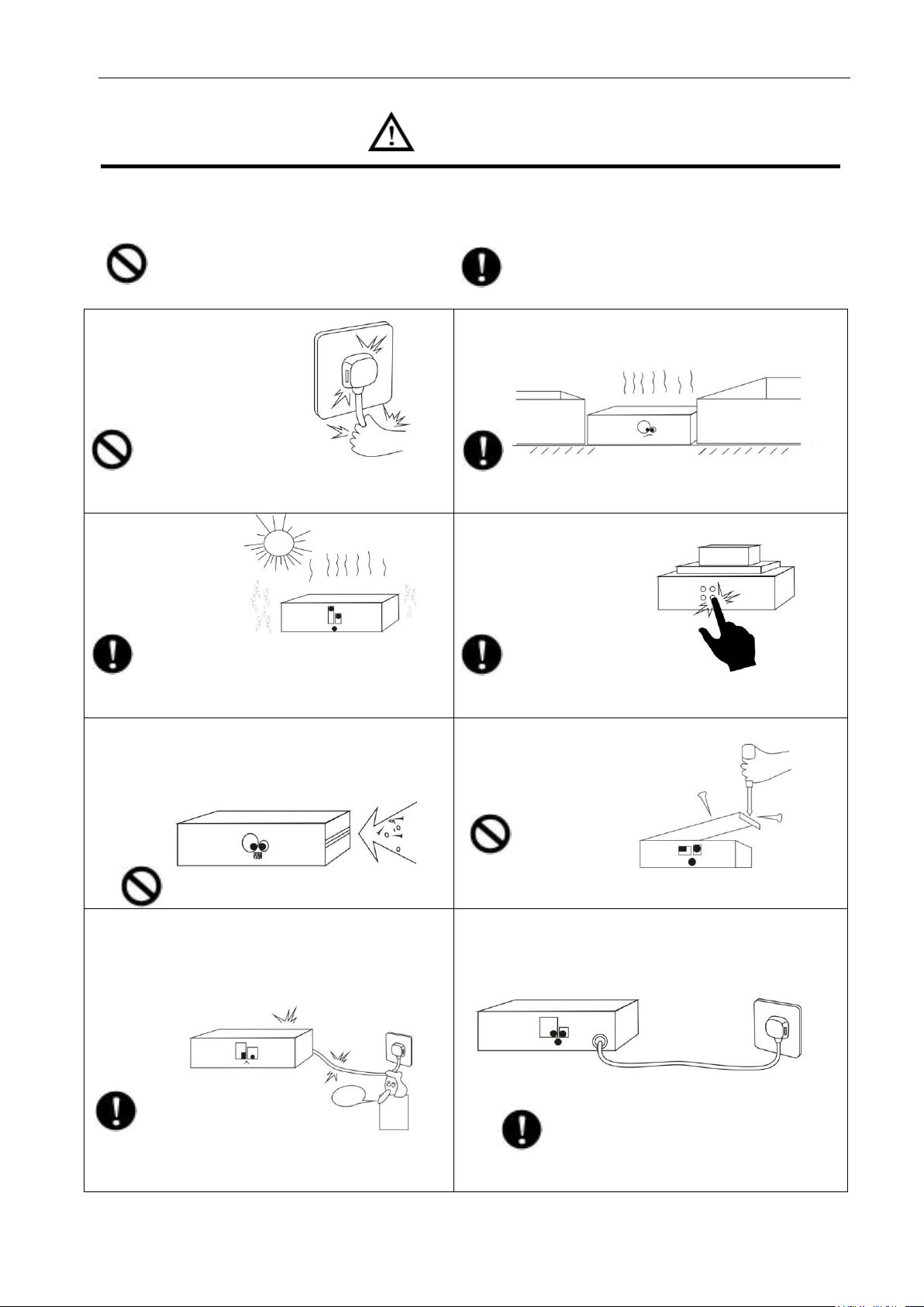
■ Please make sure that the
power wire is NOT damaged.
Do NOT unplug the equipment
by pulling the power wire;
otherwise it may cause electric
shock, short circuit or fire.
■ When the equipment is in use, DO NOT block the air
outlet which should be kept clear, in order to avoid
overheat.
■Do NOT store this
equipment in any
place with heavy
dust or vibration, or
where it is extremely
cold or hot.
■ Please do NOT place any heavy article on this
equipment. Please operate
switches, buttons or
external audio source
carefully.
■ Please prevent foreign matters (such as paper,
metal etc.) entering the equipment through the gaps
or opening, in such cases, please cut off the power
supply immediately.
■ Do NOT attempt to remove any internal component
from the equipment, or to
modify the equipment in
whatever manner.
■ In case that sound is suddenly off or there is
abnormal odor or smoke, please unplug the
equipment from the power socket to avoid potential
electric shock, fire or other accident. The equipment
should be inspected by professional personnel.
Burning Smell
■ If the equipment is not in use for a long period, please
unplug it from the AC power socket to realize zero
energy consumption.
Caution 1
2
To assure the finest performance, please use or operate the product in accordance with corresponding 3
instructions. 4
5
This symbol indicates "forbidden content" This symbol indicates "compulsory content" 6
- 4 -
Page 5

1. Product Instruction ................................................................................................................................................. 2 3
1.1 Equipment Introduction ........................................................................................................................................ 2 4
1.2 Functional Features .............................................................................................................................................. 2 5
2. Description of Appearance ..................................................................................................................................... 3 6
2.1 Front panel instructions ........................................................................................................................................ 3 7
2.2 Rear panel description .......................................................................................................................................... 4 8
3.1 Main interface operation instructions ................................................................................................................... 5 9
3.2 Volume adjustment interface operation instructions ............................................................................................. 6 10
3.3 System Settings Interface Operation Description ................................................................................................. 8 11
Safety Precautions ...................................................................................................................................................... 9 12
Matters needing attention ........................................................................................................................................... 9 13
Content 1
2
Packing List .............................................................................................................................................................. 10 14
Specification ............................................................................................................................................................. 10 15
16
1
Page 6

* M/S Amplifier
1. Product Instruction 1
1.1 Equipment Introduction 2
The DA8250 device is an eight-master-one-standby-amplifier that integrates eight power amplifier modules and a 3
sub-module and can control eight broadcast intervals. When one of the sections fails, the standby channel can also 4
be used to continue broadcasting. 5
1.2 Functional Features 6
Touch screen design, user-friendly. 7
9 channels: 8 main amplifiers, 1 standby amplifier. 8
Active/standby switching function: 8 main channels can use their respective main amplifiers, and they 9
can also automatically/manually/remotely invoke standby power amplifier. 10
Each amplifier channel has independent input and output interfaces, and one input corresponds to one 11
output. 12
Each amplifier can independently adjust the volume, the volume adjustment can be performed by the 13
machine and remotely. 14
High power switching design, with protection of over voltage, over current, high temperature, and short 15
circuit. 16
Status, volume, temperature and other operating parameters of this power amplifier can be displayed on 17
LCD screen or remote host. 18
0 ~ 100V constant voltage output. 19
Each module supports hot swap. 20
A remote control host can connect and control multiple power amplifiers at the same time. 21
With a communication interface, you can cascade multiple amplifiers. 22
23
2
Page 7

* M/S Amplifier
Public Address Amplifier 8M/S lntelligent PA Amplifier DA8250
PWR PROT
STAUS
SIG C LIP PWR PROT
STAUS
SIG C LIP P WR PROT
STAUS
SIG C LIP P WR PROT
STAUS
SIG CLIP PWR PROT
STAUS
SIG C LIP PWR PROT
STAUS
SIG C LIP P WR PROT
STAUS
SIG C LIP P WR PROT
STAUS
SIG C LIP P WR PROT
STAUS
SIG CLIP
M-250 M-250 M-250 M-250 M-250 M-250 M-250 M-250 M-250
1
2
3
4
5
6
2. Description of Appearance 1
2.1 Front panel instructions 2
4
3
5
1. Display screen 6
Touch screen can display temperature, volume and power and working status of the module. You can touch screen 7
to replace the current module by standby module. 8
2. Protection indicator(PROT) 9
This indicator lights up when the machine is automatically protected by a fault. 10
3. Pressure limit indicator(CLIP) 11
4. Output level indicator(SIG) 12
5. Power Indicator(PWR) 13
The indicator is turn on when the power of this channel is turn on. 14
6. Module replacement plug hole 15
There is no need to power off the power amplifier board when replacing it. Put the finger directly into the socket 16
and remove the power amplifier board. Then insert the new power amplifier board into the slot, and push it in 17
place. The red light will be on. The corresponding channel display status of the LCD is normal, and the power 18
amplifier board is in normal working condition. 19
When an amplifier module reports information “failure” on the LCD, the power amplifier board needs to be 20
replaced. 21
Note: When you do not need to replace the module, do not insert your finger into the insertion hole to avoid 22
broadcast interruption. 23
3
Page 8

M/S Amplifier
COM 100V
CHANNEL-9
COM 100VCOM 100VCOM 100VCOM 100VCOM 100VCOM 100VC OM 100VCOM 100V
CHANNEL-8 CHANNEL-7 CHANNEL-6 CHANNEL-5 CHANNEL-4 CHANNEL-3 CHANNEL-2 CHANNEL-1
CH-7CH-8 CH-5CH-6 CH-3CH-4 CH-1CH-2
CH9
GND IN
1
2
456
AC220V
~50/60Hz 3000W
电源开关
型号:DA8250
品名:八主一备智能广播功放
制造商:广州市迪士普音响科技有限公司
2000m
CAUTION!
RISK OF ELECTRIC SHOCK
DO NOT OPEN
警告
请勿打开,以免触电
IN IN IN IN IN IN IN IN
3
2.2 Rear panel description 1
3
2
1. AC220V power input interface 4
When the interface is connected to the AC grid, first connect the interface and turn on the power switch. 5
2. Main Amplifier Channel Output 100V Positive Terminal and COM Output Ground Terminal 6
The 100V output of the eight main power amplifier channels is the positive output of the channel, and the 7
channels of the eight main power amplifiers are independent from each other. 8
The output ground of eight main power amplifier channels is the same as the ground of the channel, and the 9
channels of the eight main power amplifiers are independent from each other. 10
3. The logo means "applicable to altitudes up to 2000 meters above sea level and non-tropical climate safety. 11
4. Eight channel input interface 12
It is used to input the audio sources of eight channels respectively. It can be connected to peripheral audio source 13
equipment. It is mainly used to connect the eight output interfaces of the intelligent host partition output module. 14
One interface corresponds to one audio source. 15
5. This interface is used for expansion. 16
6. Main power switch 17
When starting up, plug in the plug to the ~220V AC outlet and turn on the power switch. 18
When shutting down, turn off the power switch first and then pull out the machine plug. 19
20
4
Page 9

* M/S Amplifier
3. Setup Instructions 1
Boot interface 3
3.1 Main interface operation instructions 4
5
Main interface(normal display) 6
Operating parameters (Each column corresponds to the real-time display of a channel's operating parameters): 7
Temperature (%):The temperature inside the main amplifier of each channel. 8
2
Volume (%):Volume of each channel, range:0~100. 9
Power (W):Power of each channel 10
Status: The current state of each channel: self-test, normal, fault, power halved, overheated, turn off. 11
1. Self-inspection:Self-inspection at boot time 12
2. Normal:The channel's amplifier is in normal playback. 13
3.Fault:There are sub-faults, power amplifier faults, and line faults. If the channel amplifier is broken 14
and no standby power amplifier can be called, no signal will be output. 15
4. Overheat:When internal temperature of the main power amplifier of this channel detects 76°C, it 16
shows “overheat protection” and automatically switches to standby power amplifier; when 17
the temperature drops to 70°C, it will automatically switch to the main power amplifier of 18
the original channel. There is no channel installed amplifier, the corresponding column does 19
not show the operating parameters. 20
5. Turn off:The channel's power is turned off. Eight main amplifiers and one spare amplifier can be 21
5
Page 10

M/S Amplifier
turned on and off individually and remotely using the network. 1
3.2 Volume adjustment interface operation instructions 2
3
Volume adjustment interface 4
When you need to adjust the volume of a channel, touch the channel to enter the volume interface setting, and 5
slide the button or touch “+—” to adjust the channel volume. 6
Touch“ ”can turn off the channel power 7
Manual switch (OFF/ON) 8
a. Automatic call preparation (Hand tuning switch is at “OFF”): 9
8 master amplifier in the automatic call state. The priority of the standby power amplifier is: 10
The first channel has the highest priority, and the eighth channel has the lowest priority 11
Example:In the automatic call state, when channel B fails or is overheated: 12
(1) If the other amplifiers are normal and the standby power amplifier is idle, the standby power amplifier is 13
directly called to continue broadcasting. 14
(2) If the power amplifier is already occupied by the main amplifier A, the main amplifier B is compared with the 15
main amplifier A for priority comparison. 16
The priority of main amplifier B is lower than that of main amplifier A. Therefore, main amplifier B cannot call 17
the standby amplifier. The main amplifier B can only stand still and show "failure" or "overheating". 18
The priority of the main power amplifier B is higher than that of the main power amplifier A, and the main power 19
amplifier B directly seizes the standby power amplifier. Main amplifier B shows "self-tuning." 20
After the main power amplifier A loses its standby power amplifier, it shows "failure" or "overheating" at rest, and 21
the main power amplifier A stops outputting. This is an occupancy process. 22
After channel B takes up the standby power amplifier, it assigns its own volume value to the standby amplifier. 23
The power amplifier uses this volume value to control its own affiliation, so the volume does not change during 24
the whole process. Channel B is idle and its volume drops to zero. 25
(4) When the original affiliation of channel B is restarted, normal operation can be resumed. Channel B 26
automatically releases the standby amplifier. Re-allocate the work of the power amplifier. The standby power 27
amplifier is reoccupied by the current highest priority fault channel. This is the release process. 28
6
Page 11

* M/S Amplifier
(5)After channel B releases the standby power amplifier, the standby amplifier will assign the volume value to 1
channel B. Channel B uses this volume value to control its own affiliation, so the volume will not change during 2
the whole process. The spare amplifier is idle and its volume drops to zero. 3
(6) The whole process of active/standby switchover is done automatically by the machine. No manual intervention 4
is required and no dialog box will pop up. 5
b. Manually call the standby power amplifier (Hand switch is "ON") : 6
(1) Artificially moves the anti-white cursor to the designated channel and presses the digital wheel. The standby 7
power amplifier is used for the designated channel, which is called manual tuning. 8
(2) No matter the status of the channel is off, standby, normal, faulty, overheated, and the original is self-adjusting 9
or manual tuning, you can manually call the standby amplifier. 10
(3) Manually force the priority of the standby power amplifier above the automatic call. The machine will analyze 11
the situation and a corresponding warning box will pop up to remind the operator. After the operator makes a 12
decision, the machine then stays as it is, or moves to the designated channel. 13
(4) Regardless of whether the original is a self-adjusting or manual tuning state, as long as the user confirms that 14
the hand is tuned to a designated channel, it enters a manual tuning state. 15
(5) The state of manual adjustment is the result of human intentions, so it does not support any function of the 16
self-regulation state. To restore the auto-tuning state, simply reset the auto-tuning state by touching “OFF” in the 17
“manual switch”. 18
Note: Because there are 8 main power amplifier channels, it is not allowed to stop the maintenance when there are 19
several channels fault or overheat cannot work and other channels are playing. 20
21
22
23
24
25
26
27
28
29
30
31
32
33
34
35
36
37
7
Page 12

M/S Amplifier
3.3 System Settings Interface Operation Description 1
(Nine in and nine out working modes are extended functions and will not be open for the time being) 2
System Settings Interface 4
Touch on the volume adjustment interface“ ”enter the system settings interface. You can set the work mode to 5
"8 main and 1 spare” or " 9 in 9 out" , and then touch "Save".6
3
8
Page 13

* M/S Amplifier
Safety Precautions
1. Safety Precautions 1
Please do NOT connect this device to the power source, before the system is correctly wired. 2
It is important to ensure that input voltage to the device is the same as required voltage of the device, 3
otherwise the device may be damaged. 4
There is dangerous voltage in the device, which may cause personal electric shock. Please do NOT open 5
the case without permission, to avoid potential risks of electric shock. 6
The device is not completely disconnected from power source when it is switched "OFF". For sake of 7
safety, please disconnect the device from the socket if it is not in use. 8
Please do NOT place the device where it is extremely cold or hot. 9
Good ventilation must be provided in the working environment of the device, to avoid excessive 10
temperature during its operation, which may cause damages to the device. 11
Please unplug the device from power socket in raining and wet days or if the device is not in use for a 12
long time. 13
Please disconnect the power plug from sockets, to ensure the device has been completely disconnected 14
from power source, before any component is removed from or re-installed in the device or before any 15
electric connector of the device is disconnected or reconnected. 16
In case of any failure of the device, please do NOT open the case and repair without permission from a 17
professional personnel, to avoid accident or additional damages to the device. 18
Please do NOT place any corrosive chemicals near or on the device. 19
20
2.Matters needing attention 21
Our company provides a three-year free warranty service (including free replacement parts) over quality 22
issues as from the date of purchase, provided that the device is installed and used in accordance with 23
requirements specified in the User Manual. 24
For warranty, the user must show the Warranty Card and the receipt kept by the user and purchase 25
invoice of the device as supporting documents. 26
The following conditions are beyond the scope of warranty: 27
1.Product damage due to improper installation, use or handling; 28
2.Product damage due to abnormal conditions (such as excessive power source voltage or ambient 29
humidity); 30
3.Product damage due to acts of God; 31
4.Product SN is changed, altered or removed; 32
5.Product has been repaired or modified by any person without duly authorization from our company; 33
Please keep the User Manual and Warranty Card in good custody. 34
For issues and precautions not mentioned in this User Manual, if required, please contact the distributor 35
or visit our website at http://www.dsppatech.com. 36
In case of any failure in the warranty period, please contact service personnel (or distributor) of our 37
company for service. The company shall not be made liable for damages due to unauthorized 38
dis-assembly or maintenance or service by unauthorized personnel. 39
40
41
42
9
Page 14

M/S Amplifier
No.
Product list
QTY
1
16A conversion seat
1
2
Certification
1
3
Warranty Card
1 4 Instructions
1
5
Cylindrical Hexagonal Flower Black Chrome /M4×10
9
6
Semi-abrasive cross machine silk /5×19
4 7 Charter washers black
4
8
7.62MM 2P Pluggable Terminal Blocks
9
9
2P green socket 3.81MM plug
1
Index item
Parameter
Rated output power (per channel)
250W(Note: Please use the constant pressure speaker within the power range)
Rated output voltage
100V
Sensitivity
1VRMS
Signal to noise ratio
≥80dB
Frequency Range
80Hz~15kHz(±3dB)
Total harmonic distortion
≤0.5% (1K under normal working conditions)
Voltage operating range
AC220V-50Hz/60Hz Allow voltage fluctuation 15%
Rated power consumption
Single module 310W, the whole 3000W.
Machine size(L×W×H mm)
484×470×176
Package Size(L×W×H mm)
595×555×245
Net weight(Kg)
28
Gross weight(Kg)
30.5
Packing List 1
2
Specification 3
Note: The performance specifications are subject to changes without further notification. 4
5
6
7
8
9
10
11
12
13
14
15
16
17
10
Page 15

Caution
● The device is not completely disconnected from power source when it is switched "OFF". For sake of safety,
please disconnect the device from the socket if it is not in use.
● Please keep this device off water drops or splash or vase filled with water or any other articles of similar
nature.
● Please do NOT remove the cover of the equipment, otherwise you may get an electric shock. Where
necessary, repair to the equipment should be conducted by qualified professionals.
● All terminals on the device marked with are live and dangerous, and should be connected by trained
personnel.
● This is connected to power source via the plug and any failure or danger occurs, the user can disconnect the
device from power source by pulling out the plug out from the socket, therefore, it is required that the power
socket should be located somewhere with easy access.
1
Guangzhou DSPPA Audio Co., Ltd. 2
3
4
5
6
7
8
9
10
11
12
13
14
15
16
17
18
19
20
21
22
23
24
25
26
27
28
29
30
31
32
33
34
35
36
37
38
39
40
 Loading...