

DSPeaker Anti-Mode 8033 cinema, Anti-Mode 8033S-II User Manual

Anti-Mode 8033 cinema
Anti-Mode 8033S-II
User's Manual
Revision History
Rev. Date Author Affected
chapters
Description
1.0 2007-11-30 TK & ToLi All Original version Finnish and English for 8033B
1.8 2012-02-15 POj All Updated for Anti-Mode 8033 cinema and 8033S-II
1.9 2012-03-18 POj All Typo and language corrections
2.0 2012-04-23 LMa All New layout, graphics

Recycling information
The product you have purchased is marked according to the Waste
Electrical and Electronic Equipment Directive (WEEE Directive). There
are take-back systems in place that help to preserve nature and natural
resources when products are disposed of appropriately. If you need to
dispose of this product, please use the take-back system that has dedicated collection facilities for
electronic equipment. Do not put the product into household waste disposal!
Also, the product has been manufactured using parts and processes that follow the directive of the
Restriction of the use of certain Hazardous Substances in Electrical and Electronic Equipment
(RoHS).
Intended Use
The product has been designed for normal indoor use and be connected to other equipment with
cables not exceeding 3m (10 feet) in length. If you use cables of extended length, check that their
quality is sufficient and observe electrostatic discharge precautions when connecting or
disconnecting them. Use of the product outdoors, in humid or other extreme environments, may
cause reduced performance and/or risks to the user of the equipment.

ANTI-MODE 8033 CINEMA / 8033S-II
Table of contents
1. Connections and Buttons.......................................................................................4
1.1. Front panel.........................................................................................................4
1.2. Back Panel.........................................................................................................5
2. Quick Setup Guide..................................................................................................6
2.1. Before Calibration..............................................................................................7
2.2. Calibration..........................................................................................................7
2.3. After Calibration..................................................................................................8
2.4. Subwoofer Placement........................................................................................9
2.5. Cross-Over Frequency.......................................................................................9
2.6. Multiple Subwoofers.........................................................................................10
3. Wider Area Correction..........................................................................................10
3.1. Strategy 1, “Compensation of the worst response point”................................11
3.2. Strategy 2, “Gradient compensation”...............................................................11
4. Basic operation.....................................................................................................12
4.1. Bypass mode...................................................................................................12
4.2. Lifting EQ.........................................................................................................12
4.2.1. Flat..................................................................................................................12
4.2.2. Lifting 15-25Hz................................................................................................ 12
4.2.3. Lifting 25-35Hz................................................................................................ 12
4.2.4. Subsonic Filter Only........................................................................................ 13
4.2.5. Lifting 20-30Hz (Anti-Mode 8033S-II).............................................................. 13
4.3. Input Level Warning.........................................................................................13
4.4. Output Level Warning......................................................................................14
4.5. Powering Up and Down...................................................................................14
4.6. Low-pass Filter Selection (Anti-Mode 8033S-II)..............................................14
5. Connection Examples...........................................................................................17
6. Frequency Responses..........................................................................................18
6.1. Lift and Subsonic.............................................................................................18
6.2. Low-pass Filter Responses (Anti-Mode 8033S-II)...........................................19
6.3. Dipole Correction Responses (Anti-Mode 8033S-II).......................................19
7. Technical Specifications.......................................................................................20
8. Manufacturer..........................................................................................................20
9. Contact...................................................................................................................20
Rev. 2.0 18.06.2012 Page 3 (20)
ANTI-MODE 8033 CINEMA / 8033S-II
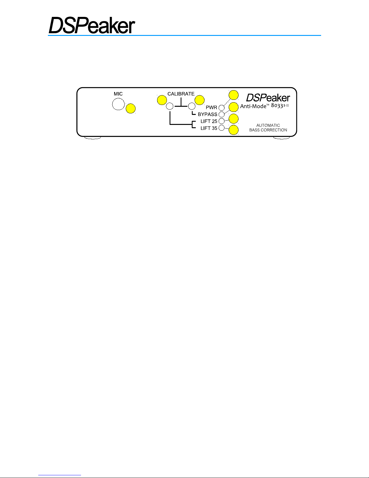
1. Connections and Buttons
1.1. Front panel
1. Microphone input jack.
2. LIFT Button: LIFT25 / LIFT35 / FLAT selector.
• Short press: Selects low frequency boost mode.
• Long press (with bypass off): Stores current settings.
• Long press (with bypass on): Enter filter selection mode (Anti-Mode 8033S-II).
3. BYPASS Button: BYPASS selector.
• Short press: Toggle Bypass mode (disable / enable processing)
• Long press: Begin secondary calibration for Wide Area Correction.
• Long press of both LIFT and BYPASS buttons: Begin main calibration.
4. PWR LED: Lit when the device is on.
• Flashes in filter edit mode, other LEDs show selected filter (Anti-Mode 8033S-II).
5. BYPASS LED: Lit when the Anti-Mode correction and lifts are bypassed.
• Flickers for 3dB input level warning (if flickers constantly, please reduce input level)
6. LIFT25 LED: Lit when the 15-25Hz lifting EQ (equalization) and subsonic filter is on.
• Is dimly lit along with the LIFT35 LED when the subsonic filter is active without lift.
• Flashes during calibration.
• Flickers for output saturation warning (please reduce input level).
7. LIFT35 LED: Lit when the 25-35Hz lifting EQ and subsonic filter is on.
• Is dimly lit along with the LIFT25 LED when the subsonic filter is active without lift.
• Flickers for input overdrive warning (please reduce input level).
Level warnings create an irregular flickering of the respective LEDs. In calibration and low-pass
filter selection mode the LEDs flash on and off in a steady pace.
Anti-Mode 8033 cinema has yellow LEDs by default.
Anti-Mode 8033S-II has blue LEDs by default.
Rev. 2.0 18.06.2012 Page 4 (20)
1
2 3
4
6
5
7
ANTI-MODE 8033 CINEMA / 8033S-II
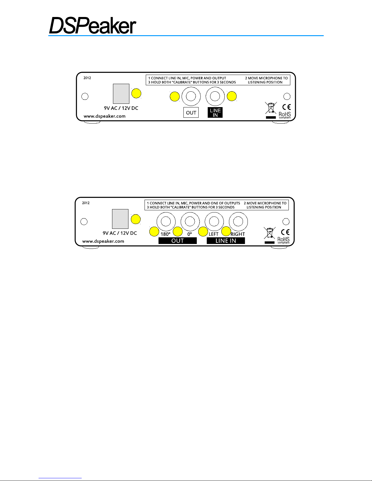
1.2. Back Panel
Anti-Mode 8033 cinema
1. 9 VAC / 12 VDC connector: Input power.
2. LINE OUT / RCA connector: To subwoofer.
3. LINE IN / RCA connector: LFE (Low-Frequency-Effects) or SUB (subwoofer) signal
from the pre-amplifier or AVR (Audio/Video Receiver).
Anti-Mode 8033S-II
1. 9 VAC / 12 VDC connector: Input power.
2. OUT 180° connector: Inverted-phase RCA out.
3. OUT 0° connector: In-phase RCA out (to subwoofer, default)
• A balanced XLR output can be created by combining the signals from the OUT 0 °
and OUT 180° connectors.
4. LEFT LINE IN / RCA connector: LFE or SUB signal from the pre-amplifier or AVR.
5. RIGHT LINE IN / RCA connector: LFE or SUB signal from the pre-amplifier or AVR.
The dual LEFT / RIGHT inputs can be used to connect stereo systems that have only stereo pre-
amplifier outputs instead of a single LFE output.
You can also connect your home theater LFE output to the LEFT input and stereo system to the
RIGHT input using an optional stereo to mono summing cable.
Both Anti-Mode 8033 models can also be connected to speaker-level outputs using a power
reduction device or a suitable resistor divider cable.
Rev. 2.0 18.06.2012 Page 5 (20)
Anti-Mode 8033 cinema Back Panel
1
2
3
Anti-Mode 8033S-II Back Panel
1
3
5
2 4
ANTI-MODE 8033 CINEMA / 8033S-II
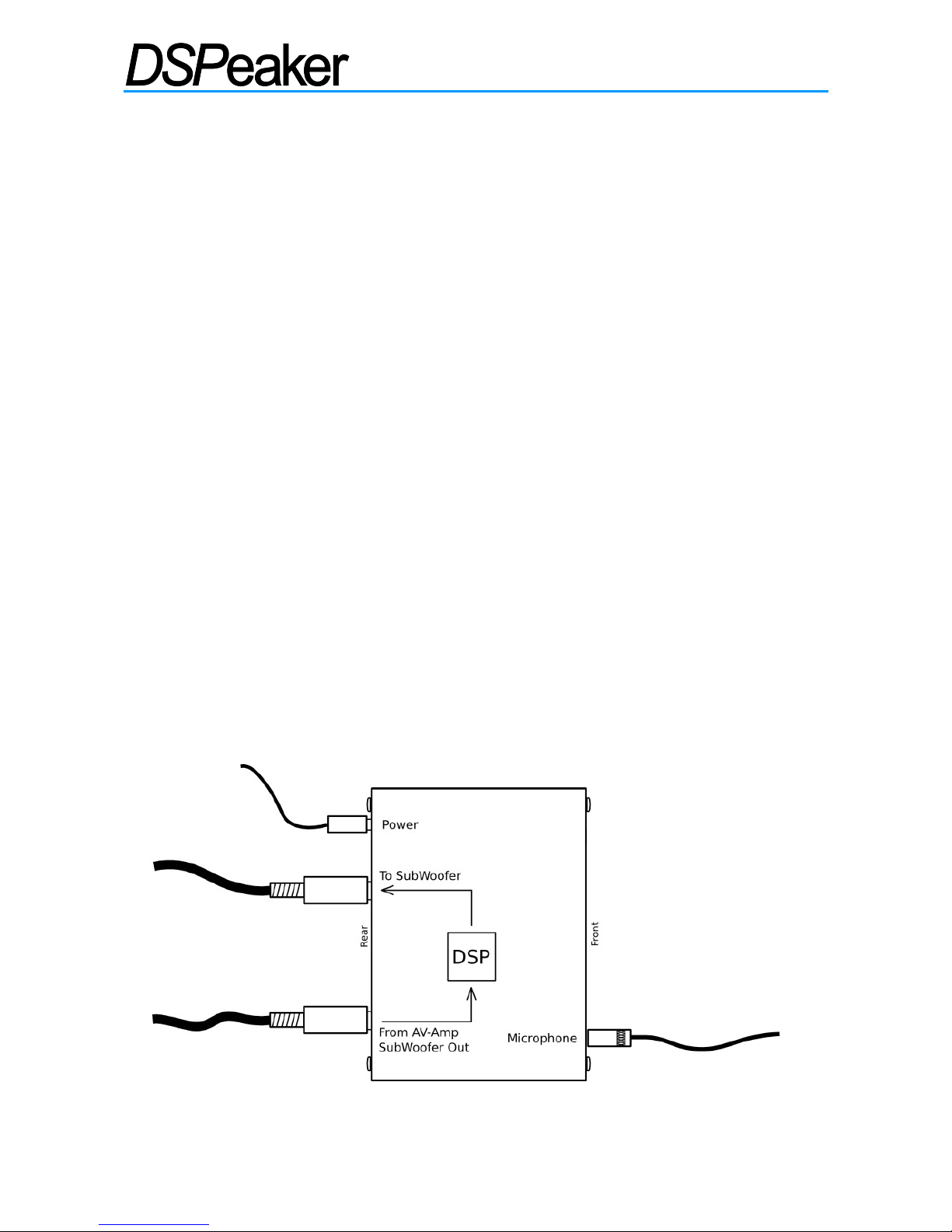
2. Quick Setup Guide
1. Please read the rest of the manual to get the most out of your system and the Anti-
Mode 8033.
2. Connect the subwoofer signal to "LINE IN" (LEFT input on the 8033S-II).
3. Connect the active subwoofer to “LINE OUT” (or OUT 0°) output.
4. Connect the microphone plug to the "MIC" jack and place and fix the microphone as
close to the listening position (head of the listener) as possible. Use of a microphone
stand helps with correct microphone placement.
5. Connect the power supply to the "9 VAC / 12 VDC" connector and wall socket.
6. Anti-Mode 8033 will turn on automatically when you plug it in.
7. Note: All LEDs on the front panel are lit if the device has never been calibrated.
8. Switch on the subwoofer and moderately reduce its volume setting.
9. Press and hold both LIFT and BYPASS buttons for three seconds to start the first
(main) calibration process. Release the buttons when the LIFT25 LED starts flashing.
10. If you keep holding the calibrate buttons down the calibration process will be aborted.
Anti-Mode will generate up to 7 frequency sweeps (depending on the complexity of the correction
required). The calibration process can last 15-30 minutes. When the LIFT25 LED stops flashing
the calibration process is completed.
For best results, run your AVR's calibration program to set speaker levels and distances after the
Anti-Mode calibration has finished.
Rev. 2.0 18.06.2012 Page 6 (20)
Setting up Anti-Mode 8033
 Loading...