

DSPeaker Anti-Mode 8033Cinema User Manual
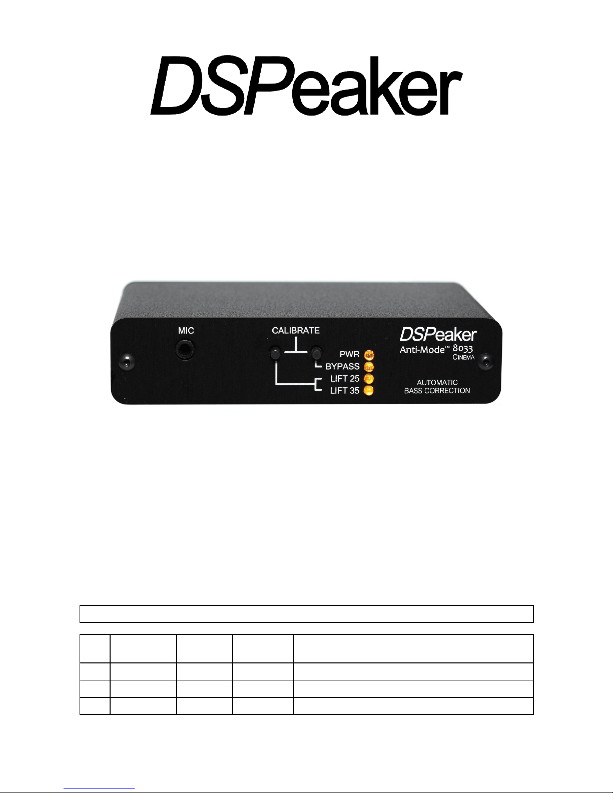
Anti-Mode 8033Cinema
User's Manual
Revision History
Rev. Date Author Affected
chapters
Description
1.0 2007-11-30 TK & ToLi All Original version Finnish and English for 8033B
1.8 2012-02-15 POj All Updated for Anti-Mode 8033Cinema and 8033S-II
1.9 2012-03-18 POj All Typo and language corrections
ANTI-MODE 8033CINEMA
Recycling information
The product you have purchased is marked according to the Waste
Electrical and Electronic Equipment Directive (WEEE Directive).
There are take-back systems in place that help to preserve nature
and natural resources when products are disposed of appropriately.
If you need to dispose of this product, use the take-back system
that has dedicated collection facilities for electronic equipment. Do
not put the product into household waste disposal!
Also, the product has been manufactured using parts and processes that follow the directive
of the Restriction of the use of certain Hazardous Substances in Electrical and Electronic
Equipment (RoHS).
Intended Use
The Anti-Mode 8033s have been designed for normal indoor use and be connected to other
equipment with cables not exceeding 3m (10 feet) in length. If you use cables of extended
length, check that their quality is sufficient and observe electrostatic discharge precautions
when connecting or disconnecting them. Use of the device outdoors, in humid or other
extreme environments, may cause reduced performance or risks to the user of the
equipment.
Rev. 1.9 2012-03-20 Page 2 (12)

ANTI-MODE 8033CINEMA
Table of contents
1. Connections and Buttons.......................................................................................4
1.1. Front panel:........................................................................................................4
1.2. Back Panel.........................................................................................................4
2. Quick Setup Guide..................................................................................................5
2.1. Before Calibration..............................................................................................5
2.2. Calibration..........................................................................................................6
2.3. After Calibration..................................................................................................6
2.4. Subwoofer Placement........................................................................................7
2.5. Cross-Over Frequency.......................................................................................7
2.6. Multiple Subwoofers...........................................................................................7
3. Wider Area Correction............................................................................................8
3.1. Strategy 1, “Compensation of the worst response point”..................................8
3.2. Strategy 2, “Gradient compensation”.................................................................8
4. Basic operation........................................................................................................9
4.1. Bypass mode.....................................................................................................9
4.2. Lifting EQ............................................................................................................9
4.2.1. Flat.................................................................................................................... 9
4.2.2. Lifting 15-25Hz..................................................................................................9
4.2.3. Lifting 25-35Hz..................................................................................................9
4.2.4. Subsonic Filter Only..........................................................................................9
4.3. Input Level Warning.........................................................................................10
4.4. Output Level Warning......................................................................................10
4.5. Powering Up and Down...................................................................................10
5. Connection Examples...........................................................................................11
6. Frequency Responses..........................................................................................11
7. Technical Specifications.......................................................................................12
8. Manufacturer..........................................................................................................12
9. Contact...................................................................................................................12
Rev. 1.9 2012-03-20 Page 3 (12)
ANTI-MODE 8033CINEMA
ANTI-MODE 8033 User's Manual
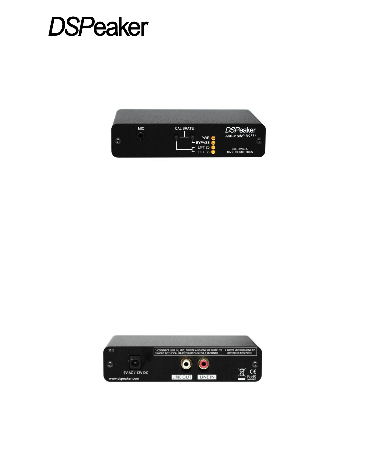
1. Connections and Buttons
1.1. Front panel:
1. Microphone input jack.
2. LIFT Button: LIFT25 / LIFT35 / FLAT selector.
• Short press: Selects low frequency boost mode.
• Long press (with bypass off): Stores current settings.
• Long press (with bypass on): Enter filter selection mode (Anti-Mode 8033S-II).
3. BYPASS Button: BYPASS selector.
• Short press: Toggle Bypass mode (disable / enable processing)
• Long press: Begin secondary calibration for Wide Area Correction.
Long press of both LIFT and BYPASS buttons: Begin main calibration.
4. PWR LED: Lit when the device is on.
• flashes in filter edit mode, other LEDs show selected filter (Anti-Mode 8033S-II).
5. BYPASS LED: Lit when the Anti-Mode correction and lifts are bypassed.
• flickers for 3dB input level warning (if flickers constantly, please reduce input level)
6. LIFT25 LED: Lit when the 15-25Hz lifting EQ (equalization) and subsonic filter is on.
• is dimly lit along with the LIFT35 LED when the subsonic filter is active without lift.
• flashes during calibration.
• flickers for output saturation warning (please reduce input level).
7. LIFT35 LED: Lit when the 25-35Hz lifting EQ and subsonic filter is on.
• is dimly lit along with the LIFT25 LED when the subsonic filter is active without lift.
• flickers for input overdrive warning (please reduce input level).
1.2. Back Panel
1. 9 VAC / 12 VDC connector: Input power.
2. LINE OUT / RCA connector: To subwoofer
3. LINE IN / RCA connector: LFE (Low-Frequency-Effects) or SUB (subwoofer) signal
from the pre-amplifier or AVR (Audio/Video Receiver).
Rev. 1.9 2012-03-20 Page 4 (12)
Figure 1: ANTI-MODE 8033 Front panel
Figure 2: ANTI-MODE 8033Cinema rear panel
 Loading...