

Page 1

DS1103 PPC Controller Board
Hardware Installation
and Configuration
Release 2014‑B – November 2014
Page 2

How to Contact dSPACE
Mail: dSPACE GmbH
Tel.: +49 5251 1638-0
Fax: +49 5251 16198-0
E-mail: info@dspace.de
Web: http://www.dspace.com
Rathenaustraße 26
33102 Paderborn
Germany
How to Contact dSPACE Support
To contact dSPACE if you have problems and questions, fill out the support request form
provided on the website at http://www.dspace.com/go/supportrequest.
The request form helps the support team handle your difficulties quickly and efficiently.
In urgent cases contact dSPACE via phone: +49 5251 1638-941 (General Technical
Support)
Software Updates and Patches
dSPACE strongly recommends that you download and install the most recent patches for
your current dSPACE installation. Visit http://www.dspace.com/go/support for software
updates and patches.
Important Notice
This document contains proprietary information that is protected by copyright. All rights
are reserved. The document may be printed for personal or internal use provided all the
proprietary markings are retained on all printed copies. In all other cases, the document
must not be copied, photocopied, reproduced, translated, or reduced to any electronic
medium or machine-readable form, in whole or in part, without the prior written consent
of dSPACE GmbH.
© Copyright 1998 - 2014 by:
dSPACE GmbH
Rathenaustraße 26
33102 Paderborn
Germany
This publication and the contents hereof are subject to change without notice.
CalDesk, ConfigurationDesk, ControlDesk, MicroAutoBox, SCALEXIO, SYNECT,
SystemDesk, TargetLink and VEOS are registered trademarks of dSPACE GmbH in the
United States or other countries, or both. Other brand names or product names are
trademarks or registered trademarks of their respective companies or organizations.
Page 3

Contents
About This Document
Document Symbols and Conventions..................................... 12
Accessing Online Help and PDF Files...................................... 13
Related Documents............................................................... 14
Safety Precautions
Safe Invehicle Usage of dSPACE Products.............................. 15
Safety Precautions for Transportation.................................... 16
Safety Precautions for Installing and Connecting the
Hardware.............................................................................. 17
Safety Precautions for Using Expansion Boxes........................ 18
Safety Precautions for Using AutoBox/Tandem-AutoBox in
a Vehicle............................................................................... 19
Safety Precautions for Using Connector Panels...................... 20
Introduction to the DS1103
Hardware.............................................................................. 21
Software............................................................................... 22
Before You Start
Installation and Configuration Overview................................ 23
Checking the System Requirements....................................... 26
11
15
21
23
Installing the Hardware
Resource Requirements of dSPACE Boards................................. .... 31
Installation in the Host PC...................................................... 31
Installation in the Expansion Box............................................ 32
Connection of MicroAutoBox to the Host PC......................... 33
Setting up the DS1103................................................................... 34
Basics on Changing I/O Base Addresses................................. 34
How to Change I/O Base Addresses....................................... 35
Installing the DS1103..................................................................... 37
How to Switch Off a dSPACE System..................................... 37
DS1103 Hardware Installation and Configuration November 2014
29
3
t
Page 4

Contents
s
t
How to Install the DS1103..................................................... 38
How to Switch On the dSPACE System.................................. 41
Installing a Connector Panel........................................................... 42
How to Connect a Panel (CP, CLP) to a Board........................ 42
How to Mount a Panel in a 19” Rack..................................... 43
Installing AutoBox/Tandem-AutoBox in a Vehicle............................ 45
Notes on Mounting and Connecting...................................... 45
Power Input Connector......................................................... 48
PX20 Expansion Box Installation................................................. .... 49
Mounting a PX20 Expansion Box in a 19'' Rack..................... 49
Maintenance Work for Expansion Boxes (PX10, PX20, AutoBox,
Tandem-AutoBox).......................................................................... 50
How to Check and Replace the Dust Filter of an Expansion
Box....................................................................................... 50
Connecting an Expansion Box to the Host
PC
Connecting via Ethernet................................................................. 54
Basics on Connecting via Ethernet......................................... 54
Connecting via Bus Interface.......................................................... 55
Link Boards Variants.............................................................. 56
Limitations With Link Boards................................................. 57
How to Establish the DS817/DS819 <–> DS814 Bus
Interface................................................................................ 58
How to Establish the DS815/DS821 <–> DS814 Bus
Interface................................................................................ 59
DS815 Connector and PC Card Link....................................... 60
Identifying the Connection Status.......................................... 62
Using dSPACE CardSafe................................................................. 65
Introduction to dSPACE CardSafe.......................................... 65
How to Mount dSPACE CardSafe.......................................... 68
How to Remove dSPACE CardSafe for Transportation............ 72
How to Remove dSPACE CardSafe Completely...................... 72
Connecting dSPACE Boxes to the Host PC via DS830................. .... 74
Features of DS830 MultiLink Panel........................................ 74
How to Connect the DS830................................................... 76
DS830: Identifying the Connection Status.............................. 78
53
4
s
DS1103 Hardware Installation and Configuration November 2014
Page 5

Contents
s
Setting Up an Ethernet Connection
Between PC and Expansion Box
Setting Up The Ethernet Connection.......................................... .... 82
Preparing the TCP/IP Configuration............................................ 84
How to Set up the TCP/IP Protocol......................................... 84
Setting Up a Peer-to-Peer Connection ....................................... 85
How to Set Up a Peer-to-Peer Connection............................. 85
Integrating the Expansion Box into a Network............................ 87
How to Change the IP Address of the Expansion Box............. 88
How to Restore the TCP/IP Configuration of the PC............... 89
How to Connect the Expansion Box to the Network and
Test the Connection.............................................................. 90
81
Connecting External Devices to the dSPACE
System
How to Connect External Devices to a Board......................... 93
How to Connect External Devices to a Connector Panel......... 95
93
t
Uninstalling the System
Removing the Hardware................................................................. 98
How to Remove the Hardware from the Host PC................... 98
How to Remove Hardware from an Expansion Box.............. 100
Connector Pinouts and LEDs
DS1103 Components................................................................... 104
Board Overview................................................................... 105
Analog Connector (P1)........................................................ 107
Digital Connector (P2)......................................................... 112
Incremental Encoder/Digital Connector (P3)......................... 117
Slave DSP Debug Connector (P6)......................................... 123
Slave DSP Flash Jumper (J1)................................................. 123
Status LEDs of the DS1103.................................................. 124
CP1103/CLP1103 Components.................................................... 127
Panel Overview.................................................................... 127
CLP1103 LED Assignment.................................................... 128
BNC Connectors (CP1 ... CP28)............................................ 129
Slave ADC Connector (CP29)............................................... 130
DS1103 Hardware Installation and Configuration November 2014
97
103
5
t
Page 6

Contents
s
t
Digital I/O Connector (CP30)................................................ 131
Slave I/O Connector (CP31).................................................. 132
Incremental Encoder Interface Connectors (CP32 ... CP37,
CP39).................................................................................. 133
CAN Connector (CP38)........................................................ 134
Master PPC UART RS232 Connector (CP40)......................... 135
Slave DSP UART RS232 Connector (CP41)............................ 136
Master PPC UART RS422 Connector (CP42)......................... 137
Slave DSP UART RS422 Connector (CP43)............................ 137
Mapping of I/O Signals
Signal Mapping to I/O Pins.................................................. 139
Conflicting I/O Features....................................................... 152
Signal Connection to External Devices
Power Supply Outputs.................................................................. 162
Electrical Characteristics....................................................... 162
Analog Inputs............................................................................... 163
I/O Circuit and Electrical Characteristics................................ 163
Analog Outputs............................................................................ 165
I/O Circuit and Electrical Characteristics................................ 166
Bit I/O........................................................................................... 168
I/O Circuits and Electrical Characteristics.............................. 169
Changing Power-up Default................................................ 170
Slave DSP Bit I/O........................................................................... 171
I/O Circuit and Electrical Characteristics................................ 172
Changing Power-up Default................................................ 174
Using the ST1PWM Pin........................................................ 174
User Interrupt Inputs.................................................................. .. 175
I/O Circuit and Electrical Characteristics................................ 175
Recognizing User Interrupts................................................. 176
Incremental Encoder Interface...................................................... 177
Digital Encoder Interface: I/O Circuit and Electrical
Characteristics..................................................................... 178
Analog Encoder Interface: I/O Circuit and Electrical
Characteristics..................................................................... 179
Recognizing Encoder Index Interrupts.................................. 181
Connecting Encoders........................................................... 182
139
161
6
s
DS1103 Hardware Installation and Configuration November 2014
Page 7

Contents
s
Supplying Power to Encoders.............................................. 186
Serial Interface........................................................................... .. 187
I/O Circuit and Electrical Characteristics................................ 188
Connecting RS232 Devices.................................................. 189
Connecting RS422 Devices.................................................. 191
CAN Bus Interface........................................................................ 193
I/O Circuit and Electrical Characteristics................................ 193
Connecting CAN Devices..................................................... 194
General Notes and Tips on Signal
Conditioning
Grounding and Shielding.............................................................. 196
Definitions of Different Ground Signals............................... 197
Grounding Signals............................................................... 197
Shielding............................................................................. 198
Avoiding Noise and Crosstalk....................................................... 200
Reducing Crosstalk.............................................................. 200
Wiring Up External Devices.................................................. 200
ADC Performance of dSPACE Boards............................................ 202
Definition of SNR................................................................. 202
Notes on Measuring Noise................................................... 203
Notes on Using AutoBox............................................................ .. 204
Grounding Scheme for AutoBox/Tandem AutoBox.............. 204
Influences on Board Performance Using AutoBox/Tandem-
AutoBox.............................................................................. 206
Filter Circuit for AutoBox/Tandem-AutoBox Power Supply.... 207
195
t
Troubleshooting
Hardware Problems...................................................................... 210
Checking the DS1103.......................................................... 210
Problems with Multiple Plug & Play Boards.......................... 211
Problems Using an Expansion Box via Bus Connection......... 213
Problems Related to the Firmware....................................... 213
Problems with the Ethernet Connection..................................... .. 214
General Errors Using Ethernet Connection........................... 214
Restoring BIOS Setup of the Slot CPU.................................. 215
Problems When Setting Up the TCP/IP Protocol.................... 216
DS1103 Hardware Installation and Configuration November 2014
209
7
t
Page 8

Contents
s
t
Problems with Peer‑To‑Peer Connection.............................. 216
Problems with the Integration of an Expansion Box in a
Network.............................................................................. 217
Data Sheets
DS1103 and CP1103/CLP1103..................................................... 220
DS1103 Data Sheet............................................................. 220
CP1103 Data Sheet............................................................. 224
CLP1103 Data Sheet............................................................ 225
Accessories
Link Boards and Panels................................................................. 228
DS814 Link Board (Box)............................................................ 228
DS814 Board Overview........................................................ 229
DS814 Data Sheet............................................................... 230
DS815 Link Board (PC)............................................................. 230
DS815 Board Overview........................................................ 231
DS815 Data Sheet............................................................... 233
DS817 Link Board (PC)............................................................. 233
DS817 Board Overview........................................................ 234
DS817 Data Sheet............................................................... 235
DS819 Link Board (PC)............................................................. 236
DS819 Board Overview........................................................ 237
DS819 Data Sheet............................................................... 238
DS821 Link Board (PC)............................................................. 239
DS821 Board Overview........................................................ 240
DS821 Data Sheet............................................................... 241
DS830 MultiLink Panel............................................................. 242
DS830 Panel Overview........................................................ 243
DS830 Data Sheet............................................................... 244
dSPACE Expansion Boxes.............................................................. 246
PX4 Expansion Box................................................................... 246
PX4 Data Sheet................................................................... 247
PX4: Ensuring Correct Operating Temperatures................... 247
PX4 Dimension Drawings.................................................... 249
PX10 Expansion Box................................................................. 249
PX10 Data Sheet................................................................. 251
219
227
8
s
DS1103 Hardware Installation and Configuration November 2014
Page 9

Contents
s
PX10: Ensuring Correct Operating Temperatures................. 252
PX10 Dimension Drawings.................................................. 256
PX20 Expansion Box................................................................. 259
PX20 Data Sheet................................................................. 261
PX20: Ensuring Correct Operating Temperatures................. 262
PX20 Dimension Drawings.................................................. 265
AutoBox.................................................................................. 268
AutoBox Data Sheet (AutoBox up to Version 3.0)................ 269
AutoBox Data Sheet (AutoBox Version 4.0 and later)........... 272
AutoBox: Ensuring Correct Operating Temperatures............ 275
AutoBox Dimension Drawings............................................. 277
Power Input Connector....................................................... 279
AutoBox Status LEDs (Integrated as of AutoBox Version
4.0)..................................................................................... 281
Lab Power Supply for AutoBox............................................ 285
Tandem-AutoBox..................................................................... 286
Tandem-AutoBox Data Sheet (Tandem-AutoBox up to
Version 4.0)......................................................................... 286
Tandem-AutoBox: Ensuring Correct Operating
Temperatures...................................................................... 289
Tandem-AutoBox Dimension Drawings................................ 291
Power Input Connector....................................................... 293
Lab Power Supply for Tandem-AutoBox............................... 295
Connector Panel Enclosures.......................................................... 297
Connector and LED Panels....................................................... 297
19" Desktop Enclosure........................................................ 297
19" Rack Enclosure.............................................................. 298
t
Index
DS1103 Hardware Installation and Configuration November 2014
299
9
t
Page 10

Contents
s
t
10
DS1103 Hardware Installation and Configuration November 2014
s
Page 11

About This Document
Contents
Required knowledge
Where to go from here
This document will show you the installation and hardware
configuration of the DS1103 PPC Controller Board and
CP1103/CLP1103 Connector Panels.
It describes the hardware installation procedure and shows how to
configure the hardware. It also gives you information about
connecting external devices to the dSPACE system.
Knowledge in handling computer hardware and Microsoft Windows
operating systems is presupposed.
Information in this section
Document Symbols and Conventions 12
Accessing Online Help and PDF Files 13
Related Documents 14
DS1103 Hardware Installation and Configuration November 2014
11
t
Page 12
ST M
About This Document
s
t
Document Symbols and Conventions
Symbols
Naming conventions
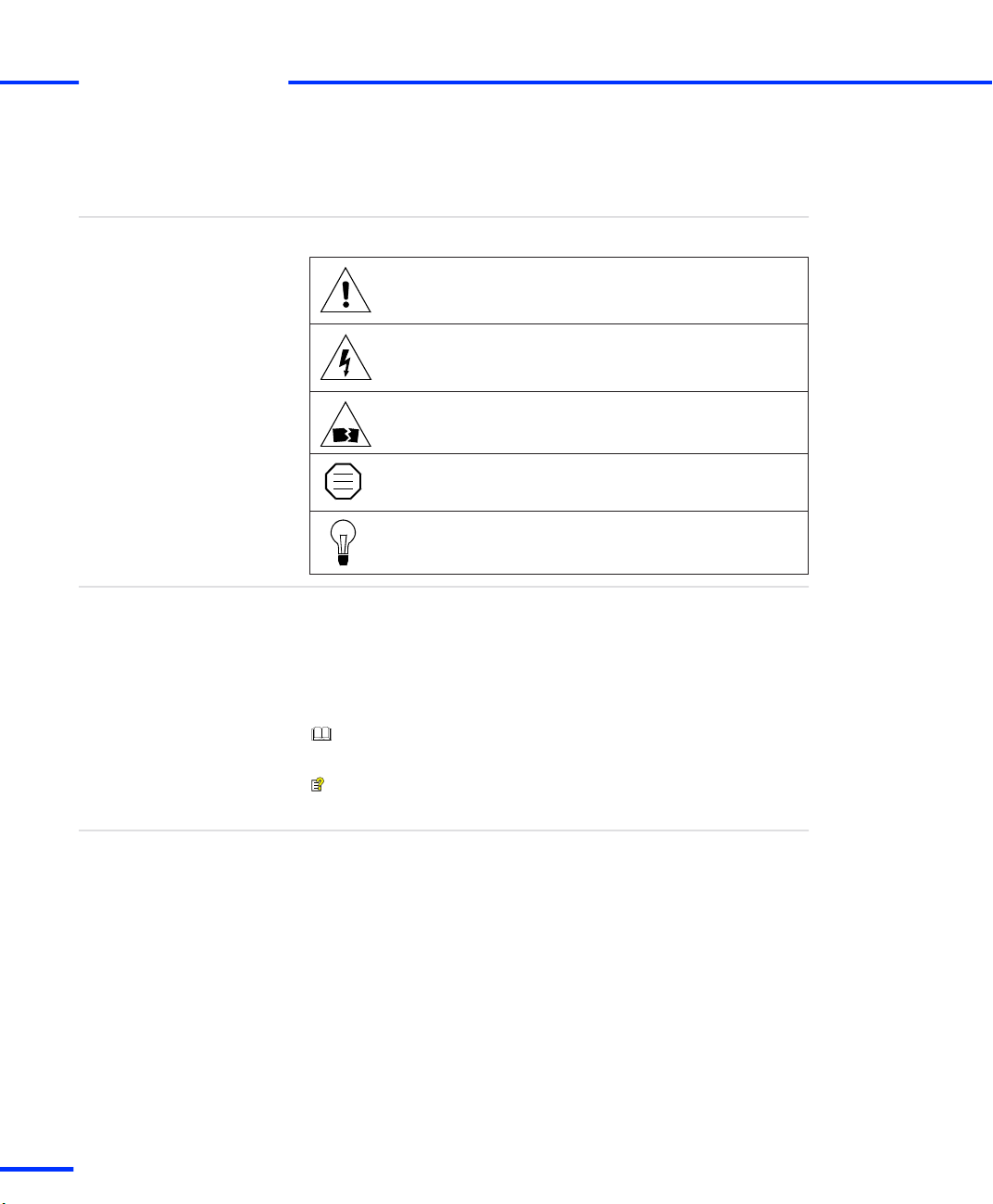
The following symbols may be used in this document.
Indicates a general hazard that may cause personal injury
of any kind if you do not avoid it by following the
instructions given.
Indicates the danger of electric shock which may cause
death or serious injury if you do not avoid it by following
the instructions given.
Indicates a hazard that may cause material damage if you
do not avoid it by following the instructions given.
Indicates important information that should be kept in
mind, for example, to avoid malfunctions.
Indicates tips containing useful information to make your
work easier.
The following abbreviations and formats are used in this document:
%name% Names enclosed in percent signs refer to environment
variables for file and path names.
< > Angle brackets contain wildcard characters or placeholders for
variable file and path names, etc.
Precedes the document title in a link that refers to another
document.
Indicates that a link refers to another document, which is available
in dSPACE HelpDesk.
Special folders
Some software products, for example, ControlDesk Next Generation
and AutomationDesk, use the following special folders:
Common Program Data folder A standard folder for applicationspecific configuration data that is used by all users.
%PROGRAMDATA%\dSPACE\<InstallationGUID>\<ProductName>
Documents folder A standard folder for user-specific documents.
%USERPROFILE%\My Documents\dSPACE\<ProductName>\
<VersionNumber>
12
DS1103 Hardware Installation and Configuration November 2014
s
Page 13
Local Program Data folder A standard folder for applicationspecific configuration data that is used by the current, non-roaming
user.
%USERPROFILE%\AppData\Local\dSPACE\<InstallationGUID>\
<ProductName>
Accessing Online Help and PDF Files
Accessing Online Help and PDF Files
s
t
Objective
Online help
After you install your dSPACE software, the documentation for the
installed products is available as online help and Adobe® PDF files.
You can access the online help, dSPACE HelpDesk, as follows:
Windows Start menu Select Start – (All) Programs –
<ProductName> – dSPACE HelpDesk (<ProductName>) to open
dSPACE HelpDesk with the start page of the selected product
displayed. You can also navigate and search in the user
documentation of any other installed software product and its
supported hardware.
Context-sensitive Press the F1 key or click the Help button in the
dSPACE software to get help on the currently active context.
In some software products, context-sensitive help is not
available.
Help menu in the dSPACE software On the menu bar, select Help
– Contents or Help – Search (not available in all software products) to
open dSPACE HelpDesk. It opens at the start page of the currently
active product. You can also navigate and search in the user
documentation of any other installed software product and its
supported hardware.
DS1103 Hardware Installation and Configuration November 2014
13
t
Page 14
About This Document
s
t
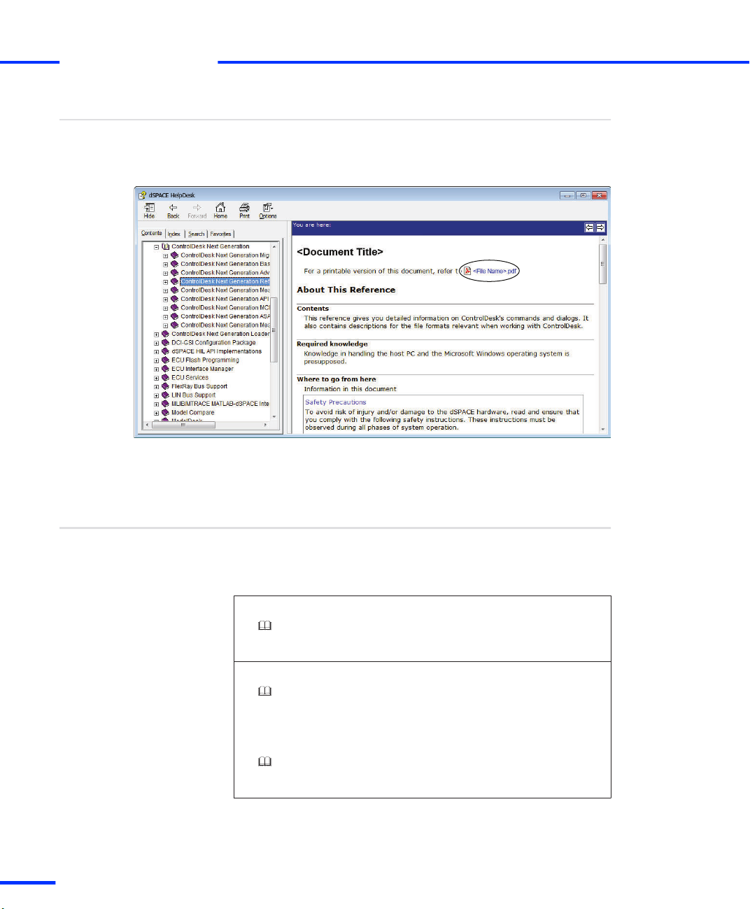
PDF files
Related Documents
You can access the PDF files as follows:
dSPACE HelpDesk Click the PDF link at the beginning of a
document:
14
Below is a list of documents that you are recommended to read when
working with the DS1103:
Information in other documents
Installation documents
Software Installation and Management Guide
Provides detailed instructions on installing and handling the dSPACE
software. It also shows you how to manage dSPACE licenses.
Getting started with the DS1103
First Work Steps with a dSPACE System
Provides information on configuring dSPACE systems after you
installed the dSPACE hardware. It shows you how to get started with
your dSPACE system after installation. This document is aimed at
users who have no experience with dSPACE systems.
DS1103 Features
Provides the feature information you need to implement your realtime models on your dSPACE hardware.
DS1103 Hardware Installation and Configuration November 2014
s
Page 15

Safety Precautions
Objective
Where to go from here
To avoid risk of injury and/or damage to the dSPACE hardware, read
and ensure that you comply with the following safety precautions.
These precautions must be observed during all phases of system
operation.
Information in this section
Safe Invehicle Usage of dSPACE Products 15
Safety Precautions for Transportation 16
Safety Precautions for Installing and Connecting the
Hardware
Safety Precautions for Using Expansion Boxes 18
Safety Precautions for Using AutoBox/TandemAutoBox in a Vehicle
Safety Precautions for Using Connector Panels 20
Safe Invehicle Usage of dSPACE Products
Guidelines for safe invehicle usage of dSPACE
products
Any in-vehicle use of dSPACE products in line with the contractual
purposes requires the use of enclosed test tracks that are specially
safety-secured for the specific purpose, i.e. with appropriately
restricted access and further appropriate safety measures.
17
19
DS1103 Hardware Installation and Configuration November 2014
15
t
Page 16

Safety Precautions
s
t
If you intend to use dSPACE products outside enclosed tracks, you
have to check with the relevant authorities in your country under
which circumstances this is possible. You and the local authorities
involved bear full responsibility for such use.
You must take appropriate measures to ensure that the overall system
enters a safe state if a dangerous situation occurs, for example, by
implementing emergency shutdown or a limp-home mode. This
especially applies in the following cases:
n Where safety-critical interventions that affect vehicle behavior are
performed, for example, the stimulation of a bus system such as
CAN, or the calibration or bypassing of in-vehicle electronic
control units (ECUs) that control powertrain, chassis, or body
systems.
n Where dSPACE products are deployed in conjunction with ECUs
which would be a hazard if they malfunctioned.
The guidelines accordingly apply to the use of dSPACE products in
aircraft or vessels in line with the contractual purposes.
Safety Precautions for Transportation
Transportation of DS1103
installed in an Expansion
Box
16
s
The DS1103 PPC Controller Board installed inside the expansion box
will be damaged during transportation and shipment!
Due to the weight of the heat sinks on the board, both the expansion
box and the board itself will be damaged by acceleration and shocks.
n For shipment and transportation, remove a DS1103 from the
expansion box (PX4, PX10 or PX20).
n Ship the board separately from the box.
n Put it in an antistatic bag and then in a strong cardboard box, in
which the board is firmly fixed against movement.
DS1103 Hardware Installation and Configuration November 2014
Page 17

Safety Precautions for Installing and Connecting the Hardware
s
Safety Precautions for Installing and Connecting the
Hardware
t
Installation sequence
Notes for handling
hardware with electrostatic
sensitive devices (ESD)
Handling boards with fans
n Install the components of your system in exactly the order stated.
Any other sequence may lead to unpredictable results or even
damage the system.
n Read the instructions carefully before starting installation.
n Note all warnings given.
dSPACE boards contain sensitive electronic devices. Before unpacking,
installing and removing them, take the following precautions to avoid
damage caused by high electrostatic voltage:
n Make sure that you and all material the board comes in contact
with are properly grounded.
n During storage or handling, place the board on conductive foam
or in a protective bag.
n Do not touch the board connectors.
Only valid for boards up to board revision DS1103‑07: Improper
handling will damage the fan of the board:
n Do not touch any components of the fan, neither during operation
nor when it has stopped.
n Do not try to stop a rotating fan with your fingers or with the help
of tools.
n Do not apply pressure to the fan bearing during installation and
removal of the board.
Installing hardware
You install dSPACE hardware at your own risk. Only qualified persons
with experience in installing computer hardware and electric devices
should perform the installation. Any damage to or malfunction of
dSPACE hardware caused by improper installation is not covered by
the warranty, unless the handling and installation instructions are
shown to be defective.
Before doing any installation work, make sure that:
n The power supplies of the host PC and the expansion box (if used)
are switched off.
No external devices are connected to the dSPACE system.
n
DS1103 Hardware Installation and Configuration November 2014
17
t
Page 18

Safety Precautions
s
t
Connecting devices
To avoid risk of injury and prevent damage to the hardware:
n Do not apply voltages/currents outside the specified ranges to the
connector pins.
n Do not connect or disconnect any devices while the dSPACE
system is powered up and/or external devices are switched on.
Make sure that the expansion box (if used) and external devices
are turned off beforehand.
Safety Precautions for Using Expansion Boxes
Objective
Installing
Grounding
To avoid damage to the expansion box and to achieve safe and
trouble-free operation, the following guidelines have to be observed.
Before doing any installation work on an expansion box:
n Make sure that the PC is turned off and no external devices are
connected to the box.
n Unplug all external connectors from all boards already installed,
because these connectors might conduct dangerous high voltage
into the chassis or parts of the circuit.
n If there is any chance that external devices connected to the
boards might conduct dangerous high voltage into the chassis,
never unplug the power cord, which is the system’s protective
ground, unless all other connectors are unplugged.
n The power cord must be plugged into a grounded wall outlet only.
Turning expansion boxes
on and off
Expansion box in use
18
s
n Before you work with an expansion box, you should always turn
on the expansion box before the host PC.
n Do not switch off the expansion box while the host PC is still
running. This might lead to unpredictable errors.
n The operating temperatures of hardware devices directly affect
their life time and their function. You must therefore ensure that
the ambient temperature of the dSPACE system does not exceed
the specified maximum temperature. For details, refer to PX4:
Ensuring Correct Operating Temperatures on page 247, PX10:
Ensuring Correct Operating Temperatures on page 252, PX20:
Ensuring Correct Operating Temperatures on page 262, or
AutoBox: Ensuring Correct Operating Temperatures on page 275.
DS1103 Hardware Installation and Configuration November 2014
Page 19

Safety Precautions for Using AutoBox/Tandem-AutoBox in a Vehicle
s
n Do not block the air vents or place the unit too close to a wall or
other obstacle.
n Guard against foreign objects (staples, etc.) falling or blowing into
the box, or liquids being spilled into it.
n Do not expose the system to excessive dust or moisture.
n The fans of the expansion boxes have a dust filter. You have to
check the dust filter for dirt at least once a year. More frequent
checks may be necessary depending on the operating conditions.
If the dust filter is dirty, you must replace it.
A dirty dust filter blocks the input air stream and increases the
temperature in the box, which may shorten the life of the
hardware components. For instructions, refer to How to Check
and Replace the Dust Filter of an Expansion Box on page 50.
Safety Precautions for Using AutoBox/Tandem-AutoBox in
a Vehicle
t
Objective
Guidelines
To avoid damage to the AutoBox/Tandem-AutoBox and to achieve
safe and trouble-free operation, the following special guidelines have
to be observed.
n Turn off the engine while connecting or disconnecting the car
battery. Even a brief disconnection of the battery while the engine
is running results in a load dump of the car generator producing
hazardous voltages of more than 100 V.
n Only valid for AutoBox up to Version 3.0 and Tandem-AutoBox up
to Version 4.0:
Double check the supply voltage polarity of the AutoBox/TandemAutoBox. Reverse polarity will immediately destroy the
AutoBox/Tandem-AutoBox power supply even if the remote
control input is turned off.
n Do not block the air intake of the fan on the rear side, and provide
sufficient space for free air flow.
n Do not operate the AutoBox/Tandem-AutoBox for extended
periods of time when the cover is removed.
DS1103 Hardware Installation and Configuration November 2014
19
t
Page 20

Safety Precautions
s
t
n The fans of the expansion boxes have a dust filter. You have to
check the dust filter for dirt at least once a year. More frequent
checks may be necessary depending on the operating conditions.
If the dust filter is dirty, you must replace it.
A dirty dust filter blocks the input air stream and increases the
temperature in the box, which may shorten the life of the
hardware components. For instructions, refer to How to Check
and Replace the Dust Filter of an Expansion Box on page 50.
Safety Precautions for Using Connector Panels
Objective
Guidelines
To avoid damage to the hardware and to achieve safe and
trouble‑free operation, the following guidelines must always be
observed.
n Before connecting a panel to a board, make sure that the PC or
the expansion box (if used) are turned off and no external devices
are connected to the panel.
n No chemicals other than alcohol (ethanol or isopropanol) should
be used to remove writing from the panel templates, since they
might damage the permanent print on the templates or even
corrode the panel.
n Guard against foreign objects (staples, etc.) falling or blowing into
the unit, or liquids being spilled into it.
n Do not expose the panel to excessive dust or moisture.
20
DS1103 Hardware Installation and Configuration November 2014
s
Page 21

Introduction to the DS1103
Objective
Where to go from here
Hardware
Board description
Installation location
The dSPACE system based on the DS1103 PPC Controller Board
comprises hardware and software.
Information in this section
Hardware 21
Software 22
The DS1103 PPC Controller Board is specifically designed for
development of high-speed multivariable digital controllers and
real‑time simulations in various fields. It is a complete real-time
control system based on a PowerPC processor. For advanced I/O
purposes, the board includes a slave-DSP subsystem based on the
Texas Instruments TMS320F240 DSP microcontroller.
The DS1103 PPC Controller Board is a standard PC/AT card that can
be plugged into a PC using the ISA bus as a backplane. The card can
also be inserted in a dSPACE expansion box communicating with the
host PC via an ISA-bus extension or Ethernet.
DS1103 Hardware Installation and Configuration November 2014
21
t
Page 22
Introduction to the DS1103
s
t
Easy access to input and
output signals
Demo equipment
Shipment
For purposes of rapid control prototyping (RCP), specific interface
connectors and connector panels provide easy access to all input and
output signals of the board.
Using an adapter cable you can link your external signals from the
100-pin I/O connector on the board to Sub-D connectors. So you can
make a high-density connection between the board and the devices
of your application via Sub-D connectors.
Specific interface connector panels provide easy access to all the input
and output signals of the DS1103 PPC Controller Board:
n The CP1103 Connector Panel provides easy-to-use connections
between the DS1103 PPC Controller Board and devices to be
connected to it. Devices can be individually connected,
disconnected or interchanged without soldering via BNC
connectors and Sub-D connectors. This simplifies system
construction, testing and troubleshooting.
n In addition to the CP1103, the CLP1103 Connector/LED Combi
Panel provides an array of LEDs indicating the states of the digital
signals.
To demonstrate control design and implementation, demo equipment
(VCFP Simulator) is available for the DS1103.
The DS1103 PPC Controller Board is a single-board system. The
package contains one board with a triple bracket and adapter cables
with six Sub-D connectors.
If you ordered the DS1103 together with an expansion box, the board
is not installed in the box.
Software
Objective
22
s
To avoid damage to the hardware during transportation,
the DS1103 PPC Controller Board is delivered separately
and has to be installed in the expansion box.
The dSPACE software, such as the implementation and the
experiment software, comes on DVD and has to be installed first. For
further information, refer to Introduction to dSPACE Software
Products on DVD ( Software Installation and Management Guide).
DS1103 Hardware Installation and Configuration November 2014
Page 23
Before You Start
Objective
Where to go from here
Make yourself familiar with the installation and configuration
procedures of the DS1103 PPC Controller Board and check if your
system fulfills the system requirements.
Information in this section
Installation and Configuration Overview 23
Checking the System Requirements 26
Installation and Configuration Overview
Installation sequence
Installing the DS1103 requires the following steps in the specified
order.
1. Check whether the software has been installed on the host PC.
N O T I C E
Changing the installation sequence may lead to
unpredictable results or even damage the system.
n Install the components of your system in exactly the
order stated.
n Read the instructions carefully before starting
installation.
n Consider all warnings given.
DS1103 Hardware Installation and Configuration November 2014
23
t
Page 24
Before You Start
s
t
You must first install the software before installing any hardware
component to the host PC and before connecting an expansion
box to it. For detailed instructions on installing the software, refer
to Installing dSPACE Software ( Software Installation and
Management Guide).
You need administrator rights to install dSPACE
software.
2. Check whether your hardware meets the requirements for
DS1103. Refer to Checking the System Requirements
on page 26.
3. Check if the default setting of the board must be changed. Refer
to Setting up the DS1103 on page 34.
4. Now you can install the hardware. Refer to How to Install the
DS1103 on page 38.
5. If the DS1103 is installed in an expansion box, connect the box to
your host PC. Refer to Connecting an Expansion Box to the Host
PC on page 53.
Configuration sequence
After you install your DS1103, you can configure it in the following
steps:
1. Set the connection mode and register your hardware.
2. Check if your platform is ready to run real-time applications.
3. The firmware of the DS1103 can be updated if you install a new
dSPACE Release.
24
DS1103 Hardware Installation and Configuration November 2014
s
Page 25

Installation and Configuration Overview
s
t
Installation problems
Next steps
If you encounter any problems during installation and
configuration:
n Check the Support section of our website.
See http://www.dspace.com/go/support.
n The FAQ section and application notes provide a lot of
useful information.
See http://www.dspace.com/go/FAQ.
n To stay up-to-date with information on possible
problems, you should periodically check the known
problem reports.
See http://www.dspace.com/go/ProblemReports.
If self-help does not solve the problem, contact dSPACE
Support and give them information about your dSPACE
environment and the problems you have. The best way to
do this is with the support request form provided on the
website at http://www.dspace.com/go/supportrequest, but
you can also send an e-mail or phone us. For details, refer
to Contacting dSPACE Support (
Software Installation
and Management Guide).
After you install and configure your system, you are ready to
implement a model – either via a Simulink model including blocks
from dSPACE’s Real‑Time Interface (RTI) or via a handcoded algorithm
– and download the corresponding application to your real‑time
hardware. ControlDesk Next Generation can be used to experiment
with your real‑time application. Refer to First Work Steps with a
dSPACE System.
External devices
Related topics
For information on connecting external devices of your application to
the dSPACE system, refer to Connecting External Devices to the
dSPACE System on page 93.
Basics
• Hardware on page 21
• Installing dSPACE Software ( Software Installation and Management Guide)
• Introduction to the DS1103 on page 21
• Software on page 22
DS1103 Hardware Installation and Configuration November 2014
25
t
Page 26

Before You Start
s
t
Checking the System Requirements
Objective
Host PC
Expansion box
Before installing dSPACE’s hardware, you have to check whether your
hardware meets the system requirements.
Your host PC must fulfill the system requirements concerning:
n The dSPACE software and other required third-party software,
n The requirements for the hardware which is needed for
connecting the host PC and the expansion box.
This connection has to be established via a bus interface.
For details, refer to Appendix: System Requirements ( Software
Installation and Management Guide).
If you want to install the DS1103 in an expansion box, the box must
fulfill the following requirements.
Required slots You need one free full-size ISA slot and two free
adjacent brackets (refer to the illustration in How to Install the
DS1103 on page 38). In addition, one free full-size ISA slot is
required by the DS814 (bus connection) or the slot CPU (Ethernet
connection).
Bus interface If you want to connect the expansion box to the host
PC via a bus interface, the DS814 has to be installed in the box.
A suitable dSPACE link board has to be installed in the host PC.
Slot CPU If you want to connect the expansion box to the host PC
via Ethernet, a slot CPU has to be installed in the box.
Keep in mind that the host PC requires a network adapter to establish
an Ethernet communication.
Resources of dSPACE
boards
26
s
The resources in the host PC and in the expansion box needed by
your dSPACE boards depend on your installation, refer to Resource
Requirements of dSPACE Boards on page 31.
DS1103 Hardware Installation and Configuration November 2014
Page 27

Checking the System Requirements
s
t
Compatibility to dSPACE
Releases
The following notes describe the compatibility of dSPACE Releases to
the different board revisions of the DS1103 PPC Controller Board:
n If you use release DS1103 Revision 09 for dSPACE Release 4.1 or
later releases:
n Programs or models that were prepared and compiled for
board revision DS1103-07 (400 MHz CPU clock, cooling by fan)
and earlier must be recompiled.
n Programs or models that were prepared and compiled for the
DS1103-09 run on earlier board revisions without changes.
However, applications that use the new functions of the
DS1103-09 are not supported on the DS1103‑07.
n If you use dSPACE Release 4.1 or earlier releases:
These releases do not support the DS1103-09.
DS1103 Hardware Installation and Configuration November 2014
27
t
Page 28

Before You Start
s
t
28
DS1103 Hardware Installation and Configuration November 2014
s
Page 29

Installing the Hardware
Objective
Shipment with expansion
box
Where to go from here
dSPACE’s real‑time boards can be installed in the host PC or in an
expansion box connected to the PC via Ethernet or a bus interface.
An expansion box is an enclosure to be used for dSPACE boards only.
It provides 20 (PX20), 10 (PX10) or 4 (PX4) full‑size 16‑bit PC/AT slots
with the standard 0.8 inch (20.3 mm) spacing.
If you order the DS1103 together with an expansion box, the DS1103
is not inserted in the expansion box. The board is shipped separately
to avoid damage to itself and to the expansion box during
transportation.
Information in this section
Resource Requirements of dSPACE Boards
Depending on the installation, dSPACE boards require resources in the
host PC and the expansion box.
Setting up the DS1103
Before inserting the DS1103 in the host PC or expansion box, you have to
check if any of the board's default settings must be changed.
Installing the DS1103
After setting up the DS1103, you can install it in your host PC or in an
expansion box.
Installing a Connector Panel
CP and CLP connector panels provide easy-to-use connections between
the board and external devices.
Installing AutoBox/Tandem-AutoBox in a Vehicle
AutoBox is an expansion box for in‑vehicle applications. After the dSPACE
boards are installed in an AutoBox, the AutoBox itself has to be installed
in a vehicle.
31
34
37
42
45
DS1103 Hardware Installation and Configuration November 2014
29
t
Page 30
Installing the Hardware
s
t
PX20 Expansion Box Installation
The PX20 Expansion Box is available as either a desktop box or a
rack‑mount version. You can also install the desktop box in a standard
19’’ rack.
Maintenance Work for Expansion Boxes (PX10,
PX20, AutoBox, Tandem-AutoBox)
The fans of various expansion boxes (PX10, PX20, AutoBox, TandemAutoBox) have a dust filter. Check the filter periodically. If it is dirty, you
must replace it.
Information in other sections
Safety Precautions for Installing and Connecting the
Hardware
49
50
17
30
DS1103 Hardware Installation and Configuration November 2014
s
Page 31

Resource Requirements of dSPACE Boards
s
Resource Requirements of dSPACE Boards
t
Objective
Where to go from here
Depending on the installation, dSPACE boards require resources in
the host PC and the expansion box.
Information in this section
Installation in the Host PC 31
Installation in the Expansion Box 32
Connection of MicroAutoBox to the Host PC 33
Installation in the Host PC
Resources in the host PC
The following table lists the required I/O address range together with
the default address and the required memory of dSPACE boards
when installed in the host PC. Some dSPACE boards support Plug &
Play in which case they require an interrupt request line (IRQ).
However the boards operate correctly even if no free IRQ is available.
The resource requirements listed in this table apply to the
host PC.
Board Slot
DS1104 PCI – – 2 x 4 KB 1 (PCI)
DS1104
(PCIe
variant)
DS815 PCMCIA 10H Plug &
DS817 PCI 10H Plug &
Required
Type
PCIe – – 2 x 4 KB 1 (PCIe)
I/O
Address
Range
Default
I/O Base
Address
Play
Play
Required
Memory
Range
None 1 (ISA)
None 1 (PCI)
Required
IRQ
DS1103 Hardware Installation and Configuration November 2014
31
t
Page 32

Installing the Hardware
s
t
Board Slot
Type
Required
I/O
Address
Default
I/O Base
Address
Required
Memory
Range
Required
IRQ
Range
DS8191)PCI
Express
DS8211)Express
Card
1)
Supported by the dSPACE software as of dSPACE Release 5.2.
10H Plug &
Play
10H Plug &
Play
None 1 (PCI
Express)
None 1 (PCI
Express)
Installation in the Expansion Box
Resources in the expansion
box
Board Required Address
DS1005 10H 300H None None
DS1006 up to board
revision DS1006-03
DS1006 as of board
revision DS1006-06
(multicore processor
board)
DS1103 10H 300H None None
DS2302 10H 380H None None
When installed in an expansion box, dSPACE boards require the
following resources in the expansion box:
The resource requirements listed in this table apply to the
expansion box, not to the host PC.
Bytes
Default I/O
Base Address
Required Memory Required
IRQ
10H 300H None None
40H 300H None None
32
The DS1007 PPC Processor Board does not need any
resources in the expansion box.
DS1103 Hardware Installation and Configuration November 2014
s
Page 33

Resource Requirements of dSPACE Boards
s
t
Resources in the host PC
The resource requirements for the host PC depend on the connection
between the host PC and the expansion box:
Connection via DS815, DS817, DS819, or DS821 Link Board The
Link Boards require the following resources in the host PC:
Required
Address Bytes
Default I/O Base
Address
Required
Memory
IRQ
10H Plug & Play None 1 n ISA for DS815
n PCI for DS817
n PCI Express for DS819/DS821
The DS819 and DS821 Link Boards are supported by the dSPACE
software since dSPACE Release 5.2.
Connection via Ethernet The boards installed in the expansion box
require no resources in the host PC.
The slot CPUs installed in the expansion box as provided by
dSPACE do not conflict with the default I/O base addresses
of dSPACE boards.
Connection of MicroAutoBox to the Host PC
Resources in the host PC
Required
Address Bytes
10H Plug & Play None 1 n ISA for DS815
MicroAutoBox can be connected to the host PC via the Link Boards
DS815, DS817, DS819 or DS821. The following resources are
required in the host PC:
Default I/O Base
Address
Required
Memory
IRQ
n PCI for DS817
n PCI Express for
DS819/DS821
DS1103 Hardware Installation and Configuration November 2014
33
t
Page 34

Installing the Hardware
s
t
Setting up the DS1103
Objective
Where to go from here
Before inserting the DS1103 in the host PC or in the expansion box,
you have to check if the default factory setting of the I/O base
address (port address) must be changed.
Information in this section
Basics on Changing I/O Base Addresses
For several conditions you have to change the default I/O base addresses
(port addresses) of dSPACE boards. This is to avoid conflicts with other
devices within your system.
How to Change I/O Base Addresses 35
Basics on Changing I/O Base Addresses
Objective
Notes and Hints
For several conditions you have to change the default I/O base
addresses (port addresses) of dSPACE boards. This is to avoid conflicts
with other devices within your system.
Note the following hints on changing the default I/O base address.
N O T I C E
Assigning I/O addresses already used by other
devices may lead to system failure, data loss on the
hard disk, and even hardware damage.
n Refer to your PC’s technical reference manual for a
description of the standard I/O map and to the
documentation of additional I/O boards that might be
inserted in the PC.
n Refer also to the lists of resources used in the diagnostic
utilities of the PC’s operating system. However, these
are not always complete.
34
34
DS1103 Hardware Installation and Configuration November 2014
s
Page 35

Setting up the DS1103
s
Note the following hints on changing the default I/O base address of
dSPACE boards:
n The I/O address ranges of dSPACE boards in your system must not
overlap. If your expansion box is connected via Ethernet, this
applies also to the address ranges of the slot CPU and the
FlashDisk.
n There are other devices like network boards or SCSI controllers
using the same I/O address range.
This does not apply if the expansion box is connected to the PC via
Ethernet or via the link boards DS815, DS817, DS819, DS821 and
DS814. In this case, only the link boards (PC) need resources in the
PC. These resources are assigned automatically by the link boards’
plug & play feature.
n If you want to install the DS1103 in an expansion box, the plug &
play circuit on the DS1103 must be disabled. This is done
automatically, when the board’s I/O base address is set to an
address other than “000H”.
n Suppose you have connected several expansion boxes to your host
PC via one of the link boards (PC) DS815, DS817, DS819 or
DS821, or via a MultiLink Panel DS830. If two (or more) of these
boxes contain a dSPACE board of the same type, you have to set
them to different I/O base addresses to allow the identification in
ControlDesk Next Generation.
n
Within an Ethernet multiconnect group, the I/O base addresses of
all included dSPACE boards must be unique.
t
Instructions on address
changing
For detailed instructions on changing the I/O base address, refer to
How to Change I/O Base Addresses on page 35.
How to Change I/O Base Addresses
Objective
Basics
Factory default setting
The I/O base address, meaning the port address, is selected via three
rotary switches on the DS1103.
Before you check and change this address, you should first read the
basic information in Basics on Changing I/O Base Addresses
on page 34.
000H
DS1103 Hardware Installation and Configuration November 2014
35
t
Page 36

0
4
8
C
0
4
8
C
0
4
8
C
S1-1 S1-2 S1-3
Installing the Hardware
s
t
Method
I/O base addresses usable
for the DS1103
To change the I/O base address
1 Set the three rotary address switches located on the component
side of the board to the desired value.
The following table shows the switch settings for some I/O base
addresses for the DS1103.
I/O Base Address (Port Address) S1-1 S1-2 S1-3
000H (default )
0 0 0
(= Plug & Play enabled)
1)
240H
0 2 4
280H 0 2 8
300H 0 3 0
310H 0 3 1
380H 0 3 8
1)
The I/O base address 240H is reserved for the slot CPU in the expansion box, if the
connection between host PC and expansion box is established via Ethernet.
Related topics
36
s
Basics
• Basics on Changing I/O Base Addresses on page 34
• Resource Requirements of dSPACE Boards on page 31
DS1103 Hardware Installation and Configuration November 2014
Page 37

Installing the DS1103
Installing the DS1103
s
t
Objective
Where to go from here
The DS1103 can be installed:
n in the host PC
n in an expansion box/AutoBox connected to the PC via Ethernet or
a bus interface
Information in this section
How to Switch Off a dSPACE System 37
How to Install the DS1103 38
How to Switch On the dSPACE System 41
Information in other sections
Safety Precautions for Installing and Connecting the
Hardware
How to Switch Off a dSPACE System
Objective
Method
You must follow the instructions below.
To switch off a dSPACE system
1 Turn off all external devices connected to the dSPACE system.
2 Shut down the host PC and turn it off.
17
Result
Related topics
Do not switch off the expansion box while the host PC
is still running. This might lead to unpredictable errors.
3 Turn off the expansion box (if used).
The dSPACE system is ready for installing or removing hardware
components and connecting or disconnecting devices.
HowTos
• How to Install the DS1103 on page 38
DS1103 Hardware Installation and Configuration November 2014
37
t
Page 38

Installing the Hardware
s
t
How to Install the DS1103
Objective
Important notes
Shipment by dSPACE
Preconditions
The following instructions will guide you through the installation of
dSPACE boards in an expansion box/AutoBox or in the host PC.
You install dSPACE hardware at your own risk. Only
qualified persons with experience in installing computer
hardware and electric devices should perform the
installation. Any damage to or malfunction of dSPACE
hardware caused by improper installation is not covered by
the warranty, unless the handling and installation
instructions are shown to be defective.
Working with more than one dSPACE board in plug & play
configuration may cause assignment problems. For details,
refer to Problems with Multiple Plug & Play Boards
on page 211.
If you ordered a DS1103 together with an expansion box, the board is
shipped separately to avoid damage to the board and to the
expansion box during transportation. Thus, you have to install the
board in the box.
n The system is switched off. For instructions, refer to How to Switch
Off a dSPACE System on page 37.
n Precautions are taken to avoid damage by high electrostatic
voltages. For details, refer to Safety Precautions for Installing and
Connecting the Hardware on page 17.
38
Method
s
To install the DS1103
WA R N I N G
Hazardous voltages
Risk of electric shock and/or damage to the hardware
Before doing any installation work, make sure that:
n The power supply of the host PC and the expansion box
(if used) are switched off.
n No external device is connected to the dSPACE system.
1 Disconnect the host PC, the expansion box and all external devices
connected to them from power supply.
DS1103 Hardware Installation and Configuration November 2014
Page 39

Installing the DS1103
s
2 Open the enclosure.
3 Select an empty full‑size 16-bit slot with two free brackets next to
it.
4 Remove the brackets that cover the openings on the rear side of
the enclosure.
N O T I C E
Improper handling will damage the fan of the
board.
Only valid for boards up to board revision DS1103-07.
n Do not touch any components of the fan, neither
during operation nor when it has stopped.
n Do not apply pressure to the fan bearing during
installation and removal of the board.
5 Insert the DS1103 and screw on the board’s triple connector.
t
DS1103 Hardware Installation and Configuration November 2014
39
t
Page 40

DS1103Triple connector bracket: P3, P2, P1
Installing the Hardware
s
t
The connector next to the board is labeled P1, the second
connector is labeled P2 and the third one P3.
Result
Next steps
40
s
6 Close the enclosure.
7 Reconnect the PC, the expansion box and all connected devices to
the power supply.
The installation is complete.
n If your system is installed in an expansion box, it must be
connected to your host PC via Ethernet or a bus interface. For
further information, refer to Connecting an Expansion Box to the
Host PC on page 53.
n You can switch on the dSPACE system. Refer to How to Switch On
the dSPACE System on page 41.
DS1103 Hardware Installation and Configuration November 2014
Page 41

Installing the DS1103
s
t
Related topics
Basics
• Safety Precautions for Installing and Connecting the Hardware on page 17
• Setting up the DS1103 on page 34
HowTos
• How to Switch Off a dSPACE System on page 37
• How to Switch On the dSPACE System on page 41
How to Switch On the dSPACE System
Objective
Precondition
Method
Result
You must follow the instructions below.
The connecting/disconnecting of devices is completed.
To switch on the dSPACE system
1 Turn on the expansion box (if used).
To avoid unpredictable errors, you should always turn
on the expansion box before the host PC.
2 Turn on the host PC.
The dSPACE system is running and you can work with it.
DS1103 Hardware Installation and Configuration November 2014
41
t
Page 42

Installing the Hardware
s
t
Installing a Connector Panel
Objective
The CP and CLP connector panels provide easy‑to‑use connections
between the board and external devices. Devices can be individually
connected, disconnected or interchanged without soldering. This
simplifies system construction, testing and troubleshooting.
The CLPs additionally provide arrays of LEDs, which indicate the states
of the digital signals.
Where to go from here
Information in this section
How to Connect a Panel (CP, CLP) to a Board
After you have installed the board in the host PC or in an expansion box,
you can connect the accompanying panel to the board.
How to Mount a Panel in a 19” Rack
As a standard, the CP and CLP connector panels are installed in a desktop
box made from aluminum profiles. They can optionally be mounted in a
19’’ industry rack.
How to Connect a Panel (CP, CLP) to a Board
Safety precautions
Preconditions
For safe and trouble‑free operation of the panels, various guidelines
must be observed. For details, refer to Safety Precautions for Using
Connector Panels on page 20.
n The system is switched off. For instructions, refer to How to Switch
Off a dSPACE System on page 37.
n If the panel is to be mounted in a 19” rack, this should be done
first (see How to Mount a Panel in a 19” Rack on page 43).
42
43
42
DS1103 Hardware Installation and Configuration November 2014
s
Page 43

Installing a Connector Panel
s
t
Method
Next steps
To connect a panel to the DS1103
N O T I C E
Connecting external devices while the power supply
is switched on may damage the dSPACE hardware.
n Do not connect or disconnect any device while the
power supply is switched on.
n Turn off the host PC, the expansion box (if used), and
the external devices beforehand.
1 Plug the CP1103 or CLP1103 to the DS1103 and tighten the lock
screws. Take care not to mix up the connectors of the DS1103.
Connectors are installed correctly when ribbon cables are not
twisted and do not cross over each other. Furthermore, the
connectors are marked by labels P1A, P1B, etc.
2 Put templates on the panel. Turn the black clips on the panel
through 90 degrees to secure the templates to the panel.
Now you can:
n Connect devices to the panel. For detailed instructions, refer to
How to Connect External Devices to a Connector Panel
on page 95.
n Switch on the dSPACE system. Refer to How to Switch On the
dSPACE System on page 41.
Related topics
Basics
• Safety Precautions for Using Connector Panels on page 20
HowTos
• How to Connect External Devices to a Connector Panel on page 95
• How to Switch Off a dSPACE System on page 37
How to Mount a Panel in a 19” Rack
Objective
The connector and LED panels are installed in a desktop box made
from aluminum profiles as a standard. They can optionally be
mounted in a 19’’ industry rack.
DS1103 Hardware Installation and Configuration November 2014
43
t
Page 44

122.5 mm
(4.82 inch)
128.5 mm
(5.06 inch)
Panel
M2.5 or M3 threads
5 mm (0.2 inch) spacing
Panel is attached by
M2.5x10 or M3x10 bolts
Installing the Hardware
s
t
Preconditions
Method
n The system is switched off. For instructions, refer to How to Switch
Off a dSPACE System on page 37.
n All connections to external devices are removed.
To mount panels in a standard 19’’ industry rack
1 Remove the aluminum box. To do so, unscrew one of its side
panels (4 screws). If there is a ribbon cable strain relief at the
bottom of the box, it must be cut open.
2 Bolt the panel to the front of a 19’’ rack as shown below.
Depending on the rack used, several M2.5x10 or M3x10 bolts are
required.
44
s
DS1103 Hardware Installation and Configuration November 2014
Page 45

Installing AutoBox/Tandem-AutoBox in a Vehicle
s
Installing AutoBox/Tandem-AutoBox in a
Vehicle
t
Objective
Where to go from here
The AutoBox/Tandem-AutoBox is the ideal environment for using
your dSPACE real-time hardware for in-vehicle control experiments. It
provides space for up to seven boards, on request even for up to 14
(one is reserved for a slot CPU), and can be mounted anywhere in a
vehicle.
Information in this section
Notes on Mounting and Connecting 45
Power Input Connector 48
Information in other sections
AutoBox 268
Tandem-AutoBox 286
Notes on Mounting and Connecting
Objective
Mounting instructions
The AutoBox/Tandem-AutoBox features a DC–DC power supply with
a remote control input that should be used to turn the power supply
on or off.
n Do not mount AutoBox/Tandem-AutoBox without rubber shoes at
the shock mounts.
n Upside down mounting is not allowed.
n For mounting you should add approx. 0.1 m (3.9 in.) space to the
outer dimensions of the AutoBox. This is to allow the
AutoBox/Tandem-AutoBox to vibrate under extreme conditions
without bumping against other devices.
n Do not block the air intake of the fan on the rear side, and provide
sufficient space for free air flow.
DS1103 Hardware Installation and Configuration November 2014
45
t
Page 46

Car battery
(+) red wire to pin A2
Melting fuse
(close to battery)
+
–
AutoBox
Remote to pin 4
(-) unmarked wire to pin A1
Car chassis
Installing the Hardware
s
t
Safety precautions
The DC–DC converter built into the AutoBox/Tandem-AutoBox lets
you operate a dSPACE system connected to a car battery. Due to the
high currents involved, special care must be taken when connecting
the AutoBox/Tandem-AutoBox power supply to the car. Wires with
high cross-section (6 mm2 minimum) are mandatory to avoid poor
performance of the power supply and excessive heating of the wires.
WA R N I N G
Hazardous voltages
Risk of electric shock
Even a brief disconnection of the battery while the engine
is running results in a load dump of the car generator
producing voltages of more than 100 V.
n Turn off the engine while connecting or disconnecting
the car battery.
N O T I C E
Only valid for AutoBox up to Version 3.0 and
Tandem-AutoBox up to Version 4.0: Reverse polarity
destroys the AutoBox/Tandem-‑AutoBox power
supply even if the remote control input is turned off.
n Double check the supply voltage polarity of
AutoBox/Tandem-AutoBox.
46
Wiring diagram
s
The wiring has to be performed according to the illustration below. If
you use Tandem-AutoBox up to Version 4.0, both power supplies
must be connected.
DS1103 Hardware Installation and Configuration November 2014
Page 47

Installing AutoBox/Tandem-AutoBox in a Vehicle
s
For operation with DC voltages > 32 V, set up a power cable with
adequate cable and fuse ratings. For further information, refer to
dSPACE support.
n The remote voltage should not exceed the supply
voltage. Overvoltage protection of the remote pin is
100 V.
n The remote voltage may be used for starting
AutoBox/Tandem-AutoBox with a remote switch: KL15,
for example (output of the ignition/driving switch).
n If you connect the remote pin to the car battery directly,
the AutoBox/Tandem-AutoBox will always be turned on,
and the car battery will soon be exhausted if the engine
is not running. Thus, a switch is highly recommended.
t
Cable supplied by dSPACE
A preconfigured cable for the supply voltage is provided by dSPACE.
This cable is intended to operate the AutoBox/Tandem-AutoBox with
a laboratory power supply during development. Therefore, pin 4
(remote) is shorted to pin A2 inside the connector in order to save a
separate switch.
Do not use this cable in the vehicle. Otherwise, the
AutoBox/Tandem-AutoBox will always be turned on.
As of March 2009, the VBAT wire (red) contains a melting fuse. The
red wire has a cross-section of 10 mm², the black wire of 6 mm².
Depending on the AutoBox/Tandem-AutoBox version, the melting
fuse has the following characteristics:
n AutoBox:
n Up to Version 3.0: 60 A/32 V, time lag
n Version 4.0 and later: 25 A/32 V, time lag (label on the cable:
CB402AB)
n Tandem-AutoBox
n Up to Version 4.0: 60 A/32 V, time lag
N O T I C E
To avoid damage, do not use a cable with cross-sections
less than 6 mm².
DS1103 Hardware Installation and Configuration November 2014
47
t
Page 48

1
2
A1
A2
3
4
5
Installing the Hardware
s
t
Power Input Connector
Objective
Each power supply unit provides a power input connector. It is a 7pin, male connector with two high‑current pins. It is adapted from a
15‑pin Sub-D connector.
Matching cable
One mating connector with connecting leads is included in the
AutoBox package (up to TandemAutoBox Version 4.0 = two
connectors). The cable for AutoBox Version 4.0 is labeled CB402AB.
Connector pinout
The following illustration shows the pinout (front view).
Connector Pin Signal Pin Signal
A2 Positive supply voltage
1)
5 Reserved, do not use
2 Reserved, do not use 4 Remote control
2)
1 Reserved, do not use 3 Reserved, do not use
A1 Negative supply voltage (0 V)
1)
Up to AutoBox Version 3.0: 8 V … 60 V DC; AutoBox Version 4.0 and later: 6 V … 60 V DC; Up to Tandem-AutoBox Version
4.0: 10 V … 60 V DC.
2)
If you use the matching cable supplied by dSPACE the remote control line is connected to positive supply voltage within the
connector shell. This cable is intended for use with a laboratory power supply only.
48
s
DS1103 Hardware Installation and Configuration November 2014
Page 49

PX20 Expansion Box Installation
PX20 Expansion Box Installation
s
t
Objective
You can install a PX20 desktop box in a 19’’ rack.
Mounting a PX20 Expansion Box in a 19'' Rack
Objective
Notes for mounting
The PX20 Expansion Box is available as either a desktop box or a
rack‑mount version. However, you can also install the desktop box in
a 19’’ rack.
n When the outer decorative cover of a PX20 is removed, its chassis
can be mounted in a standard 19’’ rack. There are five M5 threads
on either side of the chassis. The bolts should be as short as
possible to prevent short circuits inside the unit, and must not
protrude more than 5 mm (0.2") into the box. With common 19’’
racks, M5 x 6 bolts can be used.
n To prevent the system from overheating make sure that the
ventilation is not obstructed.
The plastic front cover can be snapped off and can be
replaced by a special version with rack handles, which is
available upon request.
DS1103 Hardware Installation and Configuration November 2014
49
t
Page 50

Installing the Hardware
s
t
Maintenance Work for Expansion Boxes (PX10, PX20, AutoBox, Tandem-AutoBox)
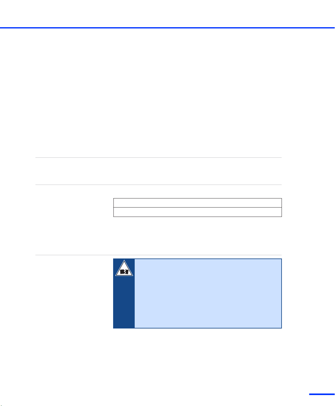
How to Check and Replace the Dust Filter of an Expansion Box
Objective
Checking interval
Effect of using dirty dust
filters
Tools and spare parts
The fans of various expansion boxes (PX10, PX20, AutoBox, TandemAutoBox) have a dust filter. Check the filter periodically. If it is dirty,
you must replace it. Cleaning the dust filter is not sufficient to restore
the characteristics of a new one.
You have to check the dust filter for dirt at least once a year. More
frequent checks may be necessary depending on the operating
conditions.
N O T I C E
A dirty dust filter blocks the input air stream and increases
the temperature in the box, which may shorten the life of
the hardware components.
You need the following tools and spare parts:
n Phillips screwdriver, PH 1
n If the filter is dirty, you need a new one: dSPACE provides a pack
of three replacement dust filters for the different expansion boxes.
The order numbers are as follows:
n PX10: FILTER_PAD_PX10
n PX20: FILTER_PAD_PX20
n AutoBox, Tandem-AutoBox: FILTER_PAD_ABX
The Tandem-AutoBox has two dust filters.
50
Method
s
To check and replace the dust filter of an expansion box
1 Switch off the expansion box or the power supply of the car
engine (if using an AutoBox, Tandem-AutoBox).
DS1103 Hardware Installation and Configuration November 2014
Page 51
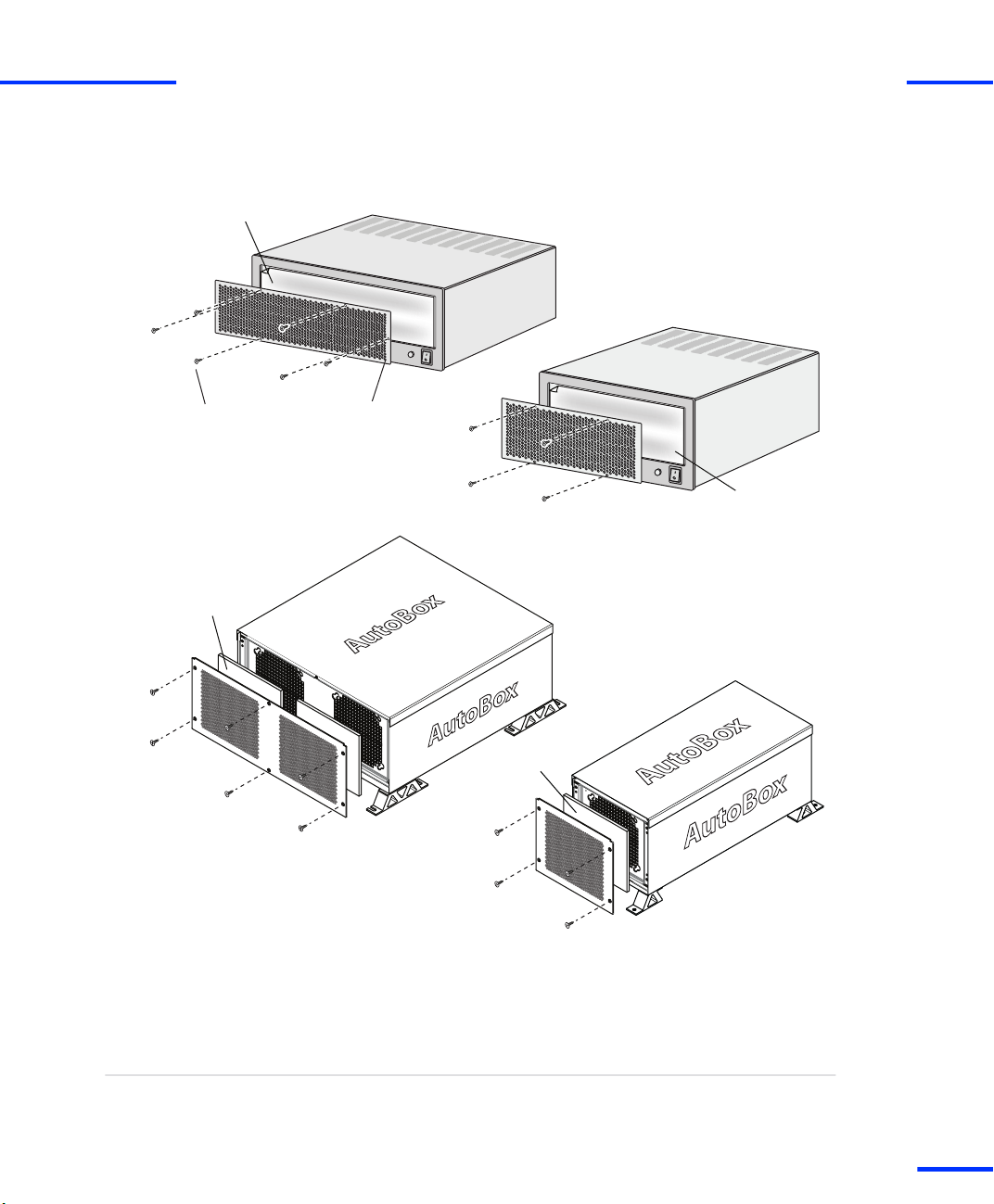
Dust filter
Perforated coverScrew (M3 )
Dust filter
Dust filter
Dust filter
PX10
AutoBox
PX20
Tandem-AutoBox
Maintenance Work for Expansion Boxes (PX10, PX20, AutoBox, Tandem-AutoBox)
s
2 Unscrew the Phillips screws (M3) as shown in the illustrations
below.
t
3 Remove the perforated cover from the box.
4 Remove the dust filter and check it for dirt. If necessary replace it
by a new one.
5 Replace the dust filter and fix it to the box with the perforated
cover and the Phillips screws (M3).
Result
You have checked and if necessary replaced the dust filter.
DS1103 Hardware Installation and Configuration November 2014
51
t
Page 52

Installing the Hardware
s
t
52
DS1103 Hardware Installation and Configuration November 2014
s
Page 53

Connecting an Expansion Box to the Host PC
Objective
Where to go from here
Expansion boxes expand the host PC for large dSPACE systems.
Information in this section
Prior to connecting or working with expansion boxes,
ensure you have familiarized yourself with the relevant
safety precautions.
Safety Precautions for Using Expansion Boxes 18
If you install your system in an expansion box, the box
must be connected to your host PC via Ethernet or a bus
interface.
Connecting via Ethernet 54
Connecting via Bus Interface 55
DS1103 Hardware Installation and Configuration November 2014
53
t
Page 54

Connecting an Expansion Box to the Host PC
s
Connecting via Ethernet
t
Where to go from here
Information in this section
Basics on Connecting via Ethernet 54
Information in other sections
Setting Up an Ethernet Connection Between PC and
Expansion Box
Basics on Connecting via Ethernet
Objective
Preconditions
Setting up a Connection
You can connect an expansion box to your host PC via Ethernet. In
this case, the expansion box is treated as a network client.
Both the host and client require a network adapter to establish
communication. The expansion box with Ethernet connection is
delivered with a slot CPU with a built‑in network adapter.
If you want to install new dSPACE boards such as the
DS1103 in an expansion box connected via Ethernet,
contact dSPACE to check the slot CPU’s compatibility with
the new boards.
After connecting the expansion box to the host PC via net cable, you
have to set up the Ethernet connection. Refer to Setting Up an
Ethernet Connection Between PC and Expansion Box on page 81.
81
Related topics
54
s
Basics
• Connecting via Bus Interface on page 55
DS1103 Hardware Installation and Configuration November 2014
Page 55

Connecting via Bus Interface
Connecting via Bus Interface
s
t
Objective
Where to go from here
You can connect an expansion box to your host PC via a bus
interface. In this case you have to install dSPACE’s link boards.
Information in this section
Before using link boards you should familiarize yourself
with the alternatives and limitations that apply to
dSPACE’s link boards.
Link Boards Variants 56
Limitations With Link Boards 57
Establishing a bus connection via link boards
How to Establish the DS817/DS819 <–> DS814
Bus Interface
How to Establish the DS815/DS821 <–> DS814
Bus Interface
Status LED for connection indication
Identifying the Connection Status
The link boards have LEDs on the bracket to indicate the current
status of the connection.
Information in other sections
Connecting via Ethernet 54
Connecting dSPACE Boxes to the Host PC via DS830
dSPACE’s DS830 MultiLink Panel allows you to connect up to 16 dSPACE
boxes to one host PC. With the DS830, you need to install only one link
board (PC) in the host PC.
58
59
62
74
DS1103 Hardware Installation and Configuration November 2014
55
t
Page 56

Connecting an Expansion Box to the Host PC
s
Link Boards Variants
t
Overview of alternatives
DS814 Link Board (Box)
DS815 Link Board (PC)
DS817 Link Board (PC)
DS819 Link Board (PC)
DS821 Link Board (PC)
If you use a bus interface to connect the host PC to an expansion box,
you currently have the five alternatives listed in the following table.
Link Boards (PC) Link Boards (Box)
DS815 DS814
DS817 DS814
DS819 DS814
DS821 DS814
The DS814 Link Board (Box) must be installed in the expansion box. It
requires a free 16‑bit ISA slot in the expansion box.
The DS815 to be installed in the host PC (usually a notebook) is a PC
Card, and requires a free PC card slot in the host PC.
The DS817 to be installed in the host PC is a PCI interface, and
requires a free PCI slot in the host PC.
The DS819 to be installed in the host PC is a PCI Express x1 interface,
and requires a free PCI Express slot (x1… x32) in the host PC.
The DS821 to be installed in the host PC (usually a notebook) is
available in two variants:
n DS821‑54 mm, requires a free ExpressCard/54 slot in the host PC
n DS821‑34 mm, requires a free ExpressCard/34 slot or a free
ExpressCard/54 slot in the host PC
To use the DS821‑34 mm in an ExpressCard/54 slot, dSPACE
highly recommends to improve lateral stability in the notebook slot
by using an ExpressCard Kit. Contact dSPACE for further
information.
56
DS1103 Hardware Installation and Configuration November 2014
s
Page 57

dSPACE recommends to use the DS821‑34 mm only in
combination with newer notebooks which provide a free
ExpressCard/34 slot. If you use them with older notebooks (for
example, which provide only ExpressCard/54 slots), your system
might crash when you boot your notebook. To solve this problem,
update the BIOS of your notebook.
It is highly recommended to use the DS821 Link Board
only in combination with the dSPACE CardSafe. For
details, refer to Using dSPACE CardSafe on page 65.
Limitations With Link Boards
Connecting via Bus Interface
s
t
Objective
Required software
Number of link boards (PC)
The following limitations currently apply for the link boards DS814,
DS815, DS817, DS819, and DS821.
The DS819 and DS821 link boards are supported as of dSPACE
Release 5.2.
n You can install only up to eight DS817, or DS819 boards in one
host PC.
n Windows allows only one DS815. This limitation also applies to
DS815 boards which are installed in the host PC via a PCI-to-PC
Card adapter.
If you want to work with more than one expansion box, use the
DS817, DS819, DS821, or DS830.
n If you want to work with several boxes, you can use the DS830
MultiLink Panel as an alternative. With the DS830, you need to
install only one link board (PC) in the host PC. For further
information, refer to Connecting dSPACE Boxes to the Host PC via
DS830 on page 74.
DS1103 Hardware Installation and Configuration November 2014
57
t
Page 58

Connecting an Expansion Box to the Host PC
s
t
Other limitations
n The length of the cable between a link board (PC) and a link board
(Box) is limited to 10 m (patch cable) and 100 m (fiber-optic cable).
n You cannot connect the dSPACE boards that are currently being
offered to the host PC via DS811 and DS812 Link Board.
n The DS815 and DS821 link boards do not support Hot-Plug mode
(= installing and uninstalling the boards while the PC is powered).
n After installing a DS815 or DS821, your host PC cannot switch to
stand-by mode.
How to Establish the DS817/DS819 <–> DS814 Bus Interface
Objective
Cables
Preconditions
The following instructions apply if you want to install a bus
connection with the link boards DS817/DS819 and DS814.
Use only the cables (crossed-over patch cable or fiber-optic cable)
which come with the hardware package.
n The system is switched off. For instructions, refer to How to Switch
Off a dSPACE System on page 37.
n A link board (DS817 or DS819) is installed in your host PC.
n The DS814 is installed in your expansion box.
Possible methods
Method 1
58
s
There are two ways you can establish a bus connection:
n Via crossed‑over patch cable. Refer to Method 1.
n Via fiber-optic cable. Refer to Method 2.
To establish the bus interface via crossed‑over patch cable
1 Connect the DS817 or the DS819 to the DS814.
Do not connect the crossed‑over patch cable to an
Ethernet LAN or the LAN connectors of a PC or a
notebook.
2 Switch on the system. Refer to How to Switch On the dSPACE
System on page 41.
DS1103 Hardware Installation and Configuration November 2014
Page 59

Connecting via Bus Interface
s
t
Method 2
Next steps
Related topics
To establish the bus interface via fiber-optic cable
N O T I C E
Bending may damage the fiber-optic cable.
n Do not bend the fiber-optic cable beyond a radius of
less than 40 mm.
1 Remove the protective caps from the connectors of the DS817 or
DS819 and DS814.
2 Remove the small protective caps from the plugs.
3 Connect the DS817 or the DS819 to the DS814.
4 Switch on the system. Refer to How to Switch On the dSPACE
System on page 41.
The dSPACE system is now ready to run real-time applications.
To check the proper installation and the board properties, and to get
started with the system, refer to the First Work Steps with a
dSPACE System document.
HowTos
• How to Install the DS1103 on page 38
• How to Switch Off a dSPACE System on page 37
How to Establish the DS815/DS821 <–> DS814 Bus Interface
Objective
Cables
The following instructions apply if you want to install a bus
connection with link boards DS815, DS821 and DS814.
n Use only the cables which come with the hardware package.
n DS815 Link Boards (PC) delivered before November 2001 are
equipped with other connectors. You need a matching link cable.
For details, refer to DS815 Connector and PC Card Link
on page 60.
n To connect the DS815 with a standard patch cable an adapter
cable is available from dSPACE. For details, refer to DS815-RJ45
adapter cable on page 62.
DS1103 Hardware Installation and Configuration November 2014
59
t
Page 60

Connecting an Expansion Box to the Host PC
s
t
dSPACE CardSafe
Preconditions
Method
Result
To hold the DS815 or DS821 firmly in a notebook slot, you can use
the dSPACE CardSafe. The dSPACE CardSafe protects a card against
unwanted removal from the host PC.
It is highly recommended to use the DS821 only in
combination with the dSPACE CardSafe.
For details, refer to Using dSPACE CardSafe on page 65.
n The system is switched off. For instructions, refer to How to Switch
Off a dSPACE System on page 37.
n A DS815 or DS821 is inserted in your host PC.
n A DS814 is installed in your expansion box.
To establish the DS815/DS821 <–> DS814 bus interface
1 Attach the connector of the DS815 or DS821 to the DS814 Link
Board (Box) with the crossed‑over patch cable.
Do not connect the crossed‑over patch cable to an
Ethernet LAN or the LAN connectors of a PC or a
notebook.
2 Switch on the system. Refer to How to Switch On the dSPACE
System on page 41.
If you use the DS821‑34 mm with older notebooks (for example,
which provide only ExpressCard/54 slots), your system might crash
when you boot your notebook. To solve this problem, update the
BIOS of your notebook.
The system is now ready to run real-time applications.
DS815 Connector and PC Card Link
PC card link cable
60
s
DS815 Link Boards (PC) delivered as of November 2001 are equipped
with a new connector and come with a new matching link cable.
DS1103 Hardware Installation and Configuration November 2014
Page 61

Old PC card link cable ... New PC card link cable
... without strain-relief clamp ... with strain-relief clamp
New DS815 connectorOld DS815 connector
Connecting via Bus Interface
s
The PC card link cables of DS815 boards delivered before November
2001 are not compatible with the new cables.
t
DS815 boards delivered before November 2001 have a
blue label. Boards delivered later have a red label, or a blue
label with “Vs. 2.0“.
DS1103 Hardware Installation and Configuration November 2014
61
t
Page 62

LED (yellow) LED (green)
Yellow Green Red
Patch cable connector Fiber-optic connector
Connecting an Expansion Box to the Host PC
s
t
DS815-RJ45 adapter cable
An adapter cable is available for the new DS815 connector to adapt
the DS815 to a standard patch cable with an RJ45 connector. The
adapter cable is labeled “DS815-RJ45 Vs 2.0”.
For the connection between the DS815-RJ45 adapter cable
and the DS814 Link Board (Box), you must use a
crossed‑over patch cable.
Identifying the Connection Status
DS814, DS817, DS819
62
s
Three LEDs on the brackets of the DS814, DS817 and DS819 indicate
the current status of the connection.
Yellow LED A lit yellow LED indicates that the connection between
the host PC and the expansion box is ready for communication.
DS1103 Hardware Installation and Configuration November 2014
Page 63

LED (yellow) LED (green)
Connecting via Bus Interface
s
Red LED A lit red LED indicates that the active connection between
the host PC and the expansion box uses a fiber-optic cable.
Green LED A lit green LED indicates that data is being sent or
received.
t
DS815
DS815-RJ45 adapter cable
The DS815 is not equipped with optical status indicators. Using the
DS815-RJ45 adapter cable, you can identify the current status of the
connection by the two LEDs integrated in the shell of the RJ45
connector.
Two LEDs indicate the current status of the connection.
Yellow LED A lit yellow LED indicates that the connection between
the host PC and the expansion box is ready for communication.
Green LED A lit green LED indicates that data is being sent or
received.
DS1103 Hardware Installation and Configuration November 2014
63
t
Page 64

Status LEDs:
Yellow
Green
Status LEDs:
Yellow
Green
Status LEDs:
Yellow
Green
DS821 - 54 mmm
DS821 - 34 mm m
DS821 - 34 mm m
Version 2 .0
Connecting an Expansion Box to the Host PC
s
t
DS821
Two LEDs indicate the current status of the connection.
64
s
Yellow LED A lit yellow LED indicates that the connection between
the host PC and the expansion box is ready for communication.
Green LED A lit green LED indicates that data is being sent or
received.
DS1103 Hardware Installation and Configuration November 2014
Page 65

Using dSPACE CardSafe
Using dSPACE CardSafe
s
t
Objective
Where to go from here
To hold the DS815 or DS821 firmly in a notebook slot, you can use
the dSPACE CardSafe. The dSPACE CardSafe protects the inserted
dSPACE link boards, cables, or connectors against unwanted removal
from the notebook and against damage.
Information in this section
Introduction to dSPACE CardSafe 65
How to Mount dSPACE CardSafe 68
How to Remove dSPACE CardSafe for
Transportation
How to Remove dSPACE CardSafe Completely 72
Introduction to dSPACE CardSafe
Overview
The dSPACE CardSafe consists of a base plate and a card holder. The
base plate is fixed to the underside of the notebook and does not
have to be removed for transportation. The card holder must be
plugged into the base plate. The height of the clamp plates can be
adapted to the notebook slot via bolt spacers.
72
DS1103 Hardware Installation and Configuration November 2014
65
t
Page 66

DS821
Notebook
Card holder
Clamp plates
Base plate
Connecting an Expansion Box to the Host PC
s
The illustration below shows the main components of dSPACE
CardSafe with a DS821‑54 mm.
t
66
s
Required mounting area
To use the DS821‑34 mm in an ExpressCard/54 slot, dSPACE highly
recommends to improve lateral stability in the notebook slot by using
an ExpressCard Kit. Contact dSPACE for further information.
The illustration below shows the position and the space required for
mounting the base plate on the underside of the notebook. You can
level out an uneven surface on the underside with acrylic foam tapes,
which are part of the delivery.
DS1103 Hardware Installation and Configuration November 2014
Page 67

65 mm
85 mm
Notebook (bottom view)
Notebook slot
with PC card
Notebook (side view)
Notebook
slot
Required area for mounting the base plate
Max. gap: approx. 20 mm
"
Template for mounting
the dSPACE CardSafe
Schablone zum Anbringen
des dSPACE CardSafe
Hier falten Fold here
dSPACE
Using dSPACE CardSafe
s
You can level out the gap between the underside of the notebook
and the notebook slot via bolt spacers. The max. gap is approx. 20
mm (see below).
t
Items delivered
Number Item Illustration
1 x Acrylic foam tape
1 x Mounting template
1 x Base plate with velcro tape
2 x Card fixture (different
2 x Clamp plate
6 x Screw (different lengths)
sizes)
dSPACE CardSafe comes as a mounting kit with the following
components:
DS1103 Hardware Installation and Configuration November 2014
67
t
Page 68

Connecting an Expansion Box to the Host PC
s
Number Item Illustration
2 x Knurled nut
10 x Bolt spacer (different
lengths)
4 x Rubber feet
1 x Mounting instructions –
The items delivered are subject to change without notice.
How to Mount dSPACE CardSafe
t
Method
To mount dSPACE CardSafe
N O T I C E
Do not mount the CardSafe over any ventilation slots
at the bottom of the notebook. This could cause
overheating and possibly destroy the notebook
processor.
68
DS1103 Hardware Installation and Configuration November 2014
s
Page 69

Step Illustration Instruction
1
2
Only if the surface of the notebook at
the mounting position is not smooth:
Remove the protective foil and put the
acrylic foam tapes on the notebook so
that there is a smooth surface at the
mounting position.
Fold and then cut the template for
mounting the dSPACE CardSafe.
Using dSPACE CardSafe
s
t
3
4
DS1103 Hardware Installation and Configuration November 2014
Center the template on the underside
of the notebook with a partially
inserted link board.
Remove the protective foil from the
velcro tape.
69
t
Page 70

Connecting an Expansion Box to the Host PC
s
Step Illustration Instruction
5
6
7
t
Press the complete CardSafe (as
delivered) to the underside of the
notebook in the opening of the
template.
The procedure is the same for each
card fixture type and for all the spacers
and screws that can be mounted.
Push a small coin on the spring of the
base plate to release the card fixture.
To avoid injury, do not use your
fingernail to unlock the connector
fixture.
While pressing the spring, unplug the
card fixture. The base plate stays in
position.
After this remove the template.
70
s
8
Fix the four rubber feet to the
underside of the notebook.
This is to compensate the height of
the CardSafe and ensure the stability
of the notebook.
DS1103 Hardware Installation and Configuration November 2014
Page 71

Step Illustration Instruction
9
10
11
Plug in the card fixture.
For a stable assembly, use the card
fixture that best fits your link board in
combination with your notebook.
Adjust the bottom clamp plate with
spacers as needed.
Plug in the link board and mount the
other clamp plate.
Using dSPACE CardSafe
s
t
12
Fix the link board/connector with the
knurled nuts.
DS1103 Hardware Installation and Configuration November 2014
71
t
Page 72

Connecting an Expansion Box to the Host PC
s
t
How to Remove dSPACE CardSafe for Transportation
Objective
Preconditions
Method
To transport the notebook in a bag, you have to remove only the card
fixture of the CardSafe.
n DS815: The connector of the DS815 Link Board is removed. The
link board can remain in the notebook.
n DS821: The DS821 Link Board is removed from the notebook.
To remove dSPACE CardSafe for transportation
Step Illustration Instruction
1
Push a small coin on the spring of the
base plate.
To avoid injury, do not use your
fingernail to unlock the connector
fixture.
2
Remove the card fixture.
How to Remove dSPACE CardSafe Completely
Objective
Preconditions
72
s
Some notebooks with an installed CardSafe may no longer fit in
docking stations. In such cases the CardSafe must be removed
completely.
n DS815: The connector of the DS815 Link Board is removed. The
link board can remain in the notebook.
n DS821: The DS821 Link Board is removed from the notebook.
DS1103 Hardware Installation and Configuration November 2014
Page 73

Using dSPACE CardSafe
s
t
Method
To remove dSPACE CardSafe completely
N O T I C E
The base plate is fixed by velcro tape. Remove the
base plate carefully when peeling the tape off, as the
bottom of a notebook is very thin and sensitive.
Step Illustration Instruction
1
2
3
Push a small coin on the spring of the
base plate.
To avoid injury, do not use your
fingernail to unlock the connector
fixture.
Remove the card fixture.
Carefully remove the base plate with a
screwdriver.
4
DS1103 Hardware Installation and Configuration November 2014
Leave the velcro tapes on the
notebook at the mounting positions.
73
t
Page 74

Host PC
Box 1
Box 2
Box 3
Box 4
Connecting an Expansion Box to the Host PC
s
t
Connecting dSPACE Boxes to the Host PC via DS830
Objective
Where to go from here
dSPACE’s DS830 MultiLink Panel allows you to connect up to 16
dSPACE boxes to one host PC. With the DS830, you need to install
only one link board (PC) in the host PC.
Information in this section
Features of DS830 MultiLink Panel 74
How to Connect the DS830 76
DS830: Identifying the Connection Status 78
Features of DS830 MultiLink Panel
Situation without DS830
You can connect several dSPACE boxes – expansion boxes and/or
MicroAutoBoxes – to one host PC. Each connection requires a
separate link board (PC) installed in the PC. The number of
dSPACE boxes you can connect to the PC is limited by the number of
free slots for link boards.
As an example, the following illustration shows how you can connect
four boxes to your PC. You require four link boards (PC) in the PC.
Situation with DS830
74
s
dSPACE’s DS830 MultiLink Panel allows you to connect up to
16 dSPACE boxes to one host PC. With the DS830, you need to install
only one link board (PC) in the host PC.
DS1103 Hardware Installation and Configuration November 2014
Page 75

Host PC
DS830
Box 1
Box 2
Box 3
Box 4
Connecting dSPACE Boxes to the Host PC via DS830
s
As an example, the following illustration shows how to connect the
DS830 to the host PC and four dSPACE boxes.
n You can connect any combination of expansion boxes
and MicroAutoBoxes to the DS830.
n You can connect several DS830 panels to one host PC.
Each DS830 has to be connected to the PC via a
separate link board (PC).
n To install your dSPACE system in a vehicle, you can use
the car battery as the power supply for the DS830.
t
Connecting and installing
the DS830
Switching on a system with
DS830
To connect the DS830 to the host PC as well as to the dSPACE boxes,
you can use any combination of crossed‑over patch cables and
fiber‑optic cables. For example, you can connect the DS830 to the
host PC and an expansion box via a fiber‑optic cable, and to a
MicroAutoBox via a patch cable.
The DS830 can be used in a laboratory or in vehicle. The cables
required to supply power to the DS830 via a mains socket or a car
battery are part of the DS830 hardware package. The cable for the
mains socket includes a power supply unit (15.0 V, 4.0 A).
For instructions on the installation, see How to Connect the DS830
on page 76.
After the boxes are connected, you can switch on the system.
To avoid unpredictable errors, you should always apply the following
sequence:
1. Turn on the dSPACE boxes (expansion boxes and/or
MicroAutoBox).
2. Turn on the DS830.
3. Turn on the host PC.
DS1103 Hardware Installation and Configuration November 2014
75
t
Page 76

Connecting an Expansion Box to the Host PC
s
t
Limitations
Data sheet
Status LEDs
Related topics
The following limitations currently apply to the DS830:
n Up to 4 (DS830/4), 8 (DS830/8) or 16 (DS830/16) dSPACE boxes
can be connected to one panel.
n The length of each connection is limited to
n 10 m (crossed‑over patch cable), and
n 100 m (fiber‑optic cable).
Therefore, the maximum distance between a host PC and a box is
200 m (DS830 connected to both the PC and the box via
fiber‑optic cables).
n DS830 panels cannot be cascaded, which means that you cannot
connect one DS830 to another. Each DS830 must be connected
directly to a link board (PC).
For the specifications of the DS830, refer to DS830 MultiLink Panel
on page 242.
The DS830 is equipped with status LEDs: see DS830: Identifying the
Connection Status on page 78.
Basics
• DS830: Identifying the Connection Status on page 78
HowTos
• How to Connect the DS830 on page 76
References
• DS830 MultiLink Panel on page 242
How to Connect the DS830
Objective
76
s
To install the DS830, you have to connect it to the host PC and the
dSPACE boxes, and supply power to the panel.
DS1103 Hardware Installation and Configuration November 2014
Page 77

Fiber-optic
connectors
Patch-cable
connectors
Connection to
host PC
Connection to
dSPACE boxes
Connection to
power supply
Connecting dSPACE Boxes to the Host PC via DS830
s
t
Panel front
Cables
Possible methods
The front of the DS830 panel provides all the connectors required for
installation. The following illustration shows the front of the DS830/8.
Use only the cable (fiber‑optic or patch cable) supplied with
the dSPACE hardware package.
The DS830 hardware package also includes the cables for connecting
the DS830 to the power supply.
You can supply power to the DS830 Multilink Panel:
n Via mains socket. Refer to Method 1.
n Via car battery. Refer to Method 2.
Method 1
Method 2
To connect the DS830 via mains socket
1 Connect the DS830 to the host PC.
2 Connect the DS830 to the dSPACE boxes (expansion box and/or
MicroAutoBoxes).
3 Use the cable with the integrated power supply unit. Plug the
power supply cable into the LEMO connector of the DS830.
To connect the DS830 via car battery
1 Connect the DS830 to the host PC.
2 Connect the DS830 to the dSPACE boxes (expansion box and/or
MicroAutoBoxes).
3 Use the cable with the unterminated end and connect this end to
the car battery. Use a 5 A fuse to protect the DS830.
DS1103 Hardware Installation and Configuration November 2014
77
t
Page 78

DS830/x
Car battery
(12 V)
Red wire
Black wire
5 A fuse
+
–
(close to battery)
Connecting an Expansion Box to the Host PC
s
The illustration below shows how to supply power to the DS830 if
installed in a vehicle.
It is highly recommended to insert a fuse into the
main power supply wire. The fuse should be
installed close to the battery.
If you connect the red wire to the car battery directly, the DS830
will always be turned on, and the car battery will soon run down if
the engine does not operate. Thus, a switch is highly
recommended.
Use only a switch and wires that are designed for
at least 5 A.
t
Further steps
After the boxes are connected, you can switch on the system.
To avoid unpredictable errors, you should always turn on
the dSPACE boxes (expansion box or MicroAutoBox) before
the DS830 MultiLink Panel (if used) and the host PC.
Related topics
Basics
• DS830: Identifying the Connection Status on page 78
DS830: Identifying the Connection Status
Objective
78
s
The front of the DS830 panel has several LEDs, which indicate the
current status of the connection to the host PC and the connected
dSPACE boxes (expansion boxes or MicroAutoBoxes), as well as the
status of the panel’s power supply.
DS1103 Hardware Installation and Configuration November 2014
Page 79

Yellow LED
(patch cable
connector)
Green LED
Red LED
Yellow LED
(fiber-optic
connector)
Fiber-optic
connector
Patch cable
connector
PC Box1
LEMO
connector
Green power LEDs
Connecting dSPACE Boxes to the Host PC via DS830
s
t
Status LEDs
The illustration below shows the status LEDs for one pair of
fiber‑optic and patch cable connectors.
Yellow LED (fiber‑optic connector) Lit if the host PC and the
corresponding dSPACE box are currently used for communication.
Red LED Lit if a fiber‑optic cable is used.
Green LED Lit when data is being sent or received.
Yellow LED (patch cable connector) Lit if the connection to the
host PC or a connected dSPACE box is ready for communication.
Green power LEDs Lit both when power is supplied correctly to the
DS830.
Related topics
HowTos
• How to Connect the DS830 on page 76
DS1103 Hardware Installation and Configuration November 2014
79
t
Page 80

Connecting an Expansion Box to the Host PC
s
t
80
DS1103 Hardware Installation and Configuration November 2014
s
Page 81

Setting Up an Ethernet Connection Between PC and Expansion Box
Objective
You can connect an expansion box (AutoBox/Tandem‑AutoBox) to
your host PC via Ethernet. In this case, the expansion box is treated as
a network client.
Establishing a connection between an expansion box and
the host PC via Ethernet is recommended for advanced
users only.
DS1103 Hardware Installation and Configuration November 2014
81
t
Page 82

Setting Up an Ethernet Connection Between PC and Expansion Box
s
Setting Up The Ethernet Connection
t
Objective
The connection between the PC (host) and an expansion box (client)
is based on the TCP/IP protocol provided by Windows 7. There are
two ways to connect a client to the host:
n Peer-to-peer connection (P2P)
The expansion box and the host PC are directly connected in a
peer-to-peer configuration, and neither the host nor the client is
connected to any other network.
n Integration in an existing network
The expansion box becomes part of an existing network using
TCP/IP, for example, a local area network.
82
DS1103 Hardware Installation and Configuration November 2014
s
Page 83

Preparing the
TCP/IP Protocol
How to Set Up the TCP/IP Protocol
How to Set Up a Peer-to-Peer
Connection
Integrating the Expansion
Box into a Network
How to Change the IP Address
of the Expansion Box
How to Restore the TCP/IP
Configuration of the PC
How to Connect the Expansion
Box to the Network and
Test the Connection
Yes
No
How to Set Up a
Peer-to-Peer Connection
Connecting an Expansion
Box via Ethernet
Integrate
the Expansion
Box into an Existing
Network?
Expansion Box
Ready for Use
Setting Up The Ethernet Connection
s
t
Setup procedure
To connect an expansion box via Ethernet, follow the instructions
given in the flow chart below. The boxes in the flow chart refer to the
corresponding sections in the text.
Where to go from here
Information in this section
Preparing the TCP/IP Configuration 84
Setting Up a Peer-to-Peer Connection 85
Integrating the Expansion Box into a Network 87
DS1103 Hardware Installation and Configuration November 2014
83
t
Page 84

Setting Up an Ethernet Connection Between PC and Expansion Box
s
Preparing the TCP/IP Configuration
How to Set up the TCP/IP Protocol
t
Objective
Precondition
Previous configuration
Method
Before you can connect the expansion box to the host PC via
Ethernet, you have to set up the TCP/IP protocol of the network
adapter in your host PC.
Setting up the TCP/IP configuration requires administrator
rights.
During this procedure, write down the previous TCP/IP configuration
for later restoration.
To set up the TCP/IP protocol
1 On the example of Windows 7:
From the Start menu, choose (depending on your PC
configuration):
n Settings – Network Connections
n Settings – Control Panel – Double‑click Network Connections
and Sharing Center.
n Control Panel – Double‑click Network Connections and Sharing
Center.
2 Double‑click Local Area Connection
- or -
Click View Status of Local Area Connection.
The Local Area Connection Status dialog opens.
3 Click Properties.
The Local Area Connection Properties dialog opens.
4 Select Internet Protocol Version 4 (TCP/IPv4), and click Properties.
The Internet Protocol (TCP/IP) Properties dialog opens.
5 From the Internet Protocol (TCP/IP) Properties dialog, write down
all the configured values and options so that you can restore them
later.
84
DS1103 Hardware Installation and Configuration November 2014
s
Page 85

Setting Up The Ethernet Connection
s
6 From the Internet Protocol (TCP/IP) Properties dialog, select Use
the Following IP address. Enter the value
Address edit field.
7 In the Subnet Mask edit field, enter the value
8 Click OK to close the Internet Protocol (TCP/IP) Properties dialog.
9 Click OK to close the Local Area Connection Properties dialog.
10 Click Close to close the Local Area Connection Status dialog.
11 If prompted, confirm to restart the host PC.
192.100.100.1
255.255.255.0
in the IP
.
t
Next steps
Solving problems
Proceed with:
n How to Set Up a Peer-to-Peer Connection on page 85 or
n Integrating the Expansion Box into a Network on page 87.
If a problem occurs when you set up the TCP/IP protocol,
see Problems When Setting Up the TCP/IP Protocol
on page 216.
Setting Up a Peer-to-Peer Connection
How to Set Up a Peer-to-Peer Connection
Objective
A peer-to-peer connection between the host and client means that
neither the host nor the client is connected to any other network.
You must carry out this step, even if you want to integrate the
expansion box into an existing network. In that case the IP address of
the expansion box must comply with the conventions of the network.
So its default IP address (192.100.100.98) must be changed after
setting up a peer-to-peer connection between the host PC and the
expansion box.
Method
To set up and test a peer‑to‑peer connection
1 If the host PC is already part of an existing network, switch it off,
and disconnect it from the network.
DS1103 Hardware Installation and Configuration November 2014
85
t
Page 86
Setting Up an Ethernet Connection Between PC and Expansion Box
s
2 Connect the expansion box to the host PC, using the supplied
crossed‑over patch cable.
For a peer-to-peer connection, the crossed‑over patch
cable supplied with the expansion box must be used. If
connecting to an existing network, for example, via a
hub, a standard patch cable must probably be used. If
you are uncertain, ask your network administrator.
3 Turn on the expansion box.
During booting, the expansion box beeps several times. The last
beep sequence indicates whether the default IP address is active
(three short beeps) or if the IP address has been changed by the
user (one long beep). In the following it is assumed that the
default IP address (192.100.100.98) is active.
4 Turn on the host PC.
The host PC will take longer to boot and will display
error messages because of the missing connection to
the network. Ignore these error messages for now.
The connection between the host PC and the expansion box can
now be tested.
5 Open a Command Prompt window (DOS window): For example,
from the Start menu, choose Run ..., enter cmd and click OK.
6 Enter the command:
ping 192.100.100.98
address of the expansion box.
If the following message appears, the peer-to-peer connection is
ready for use (the values vary on different computers and
networks):
Pinging 192.100.100.98 with 32 bytes of data:
Reply from 192.100.100.98: bytes=32 time<10ms TTL=32
Reply from 192.100.100.98: bytes=32 time<10ms TTL=32
Reply from 192.100.100.98: bytes=32 time<10ms TTL=32
Reply from 192.100.100.98: bytes=32 time<10ms TTL=32
t
, which is the default IP
Next steps
86
s
n If the expansion box is used only in a peer-to-peer connection, the
network setup is now complete. Continue with the First Work
Steps with a dSPACE System document.
n If the expansion box is to be used in an existing network, proceed
with How to Change the IP Address of the Expansion Box
on page 88.
DS1103 Hardware Installation and Configuration November 2014
Page 87

Setting Up The Ethernet Connection
s
t
Solving problems
If any problem comes up when you set up a peer-to-peer
connection, see Problems with Peer‑To‑Peer Connection
on page 216.
Integrating the Expansion Box into a Network
Setup procedure
The following instructions show how to integrate an expansion box
into an existing network step‑by‑step:
1. A peer-to-peer connection is needed temporarily to change the IP
address of the expansion box. Refer to How to Set Up a Peer-to-
Peer Connection on page 85.
2. The IP address of the expansion box must be changed to comply
with the IP addresses used in the network. Refer to How to
Change the IP Address of the Expansion Box on page 88.
3. After you have changed the IP address of the expansion box, you
can restore the previous IP address of the host PC. Refer to How to
Restore the TCP/IP Configuration of the PC on page 89.
4. Finish the work with How to Connect the Expansion Box to the
Network and Test the Connection on page 90.
Where to go from here
Information in this section
How to Change the IP Address of the Expansion Box 88
How to Restore the TCP/IP Configuration of the PC 89
How to Connect the Expansion Box to the Network
and Test the Connection
Information in other sections
How to Set Up a Peer-to-Peer Connection
After setting up the TCP/IP protocol, you can set up the peer-to-peer
connection.
DS1103 Hardware Installation and Configuration November 2014
90
85
87
t
Page 88

Setting Up an Ethernet Connection Between PC and Expansion Box
s
t
How to Change the IP Address of the Expansion Box
Setip utility
Preconditions
Method
To change the IP address, use the
<InstallationFolder>\exe
n Before trying to change the IP address, be sure that you
setip
utility located in
.
have tested the peer-to-peer connection to your
expansion box via the ping command.
n The IP address of the expansion box can be changed
only if the old IP address is known and the host can
connect to the expansion box. If the IP address of the
expansion box is unknown, refer to IP Address lost
on page 214.
To change the IP Address
1 Contact your network administrator to obtain an unused IP
address that you can use for the expansion box.
2 Open a Command Prompt window (DOS window): For example,
from the Start menu, choose Run ..., enter cmd and click OK.
3 Enter the command
setip <current IP address> <new IP
address>
The new IP address will be valid after rebooting the the expansion
box.
Write down the new IP address of the expansion box.
You will need it later to establish the connection.
88
s
Example
Next step
The default IP address of the expansion box is 192.100.100.98. The IP
address assigned to the host PC for the peer-to-peer connection is
192.100.100.1. With these settings the host PC can connect to the
expansion box as described in How to Set Up a Peer-to-Peer
Connection on page 85. Assume that the IP address of the host PC
was previously set to 183.27.33.14. The IP address to be used for the
expansion box is 183.27.33.18.
In a Command Prompt window (DOS window), enter the command:
setip 192.100.100.98 183.27.33.18
Proceed with How to Restore the TCP/IP Configuration of the PC
on page 89.
DS1103 Hardware Installation and Configuration November 2014
Page 89

Setting Up The Ethernet Connection
s
How to Restore the TCP/IP Configuration of the PC
t
Objective
Precondition
Method
After you have changed the IP address of the expansion box to
integrate it in a network, you can restore the previous IP address of
the host PC.
To restore the TCP/IP configuration of the host PC, you need the
values and options which you wrote down when setting up the
TCP/IP protocol (see How to Set up the TCP/IP Protocol on page 84).
To restore the TCP/IP configuration of the host PC
1 On the example of Windows 7:
From the Start menu, choose (depending on your PC
configuration):
n Settings – Network Connections
n Settings – Control Panel – Double‑click Network Connections
and Sharing Center.
n Control Panel – Double‑click Network Connections and Sharing
Center.
2 Double‑click Local Area Connection
- or -
Click View Status of Local Area Connection.
The Local Area Connection Status dialog opens.
3 Click Properties.
The Local Area Connection Properties dialog opens.
4 Select Internet Protocol Version 4 (TCP/IPv4), and click Properties.
The Internet Protocol (TCP/IP) Properties dialog opens
5 Enter all the configured values and options you wrote down
before.
6 Click OK to close the Internet Protocol (TCP/IP) Properties dialog.
7 Click OK to close the Local Area Connection Properties dialog.
8 Click Close to close the Local Area Connection Status dialog.
9 If prompted, confirm to restart the host PC.
Next steps
Proceed with How to Connect the Expansion Box to the Network and
Test the Connection on page 90.
DS1103 Hardware Installation and Configuration November 2014
89
t
Page 90

Setting Up an Ethernet Connection Between PC and Expansion Box
s
t
How to Connect the Expansion Box to the Network and Test the Connection
Cabling
Method
Result
The supplied crossed‑over patch cable cannot be used to
connect the expansion box to an existing network. Use a
normal (non crossed‑over) cable.
To connect the expansion box to the network and test the
connection
1 Turn off the host PC and the expansion box.
2 Connect the expansion box and the host PC to the network.
3 Turn on the expansion box.
To avoid unpredictable errors, you should always turn
on the expansion box before the host PC.
4 Turn on the host PC.
The connection between the host PC and the expansion box can
now be tested.
5 Open a Command Prompt window (DOS window): For example,
from the Start menu, choose Run ..., enter cmd and click OK.
6 Enter the command:
ping<IP address of the expansion box>.
If the following message appears, the network connection is ready for
use (the values vary on different computers and networks). The IP
address 10.1.202.178 serves as an example.
Pinging 10.1.202.178 with 32 bytes of data:
Reply from 10.1.202.178: bytes=32 time<10ms TTL=32
Reply from 10.1.202.178: bytes=32 time<10ms TTL=32
Reply from 10.1.202.178: bytes=32 time<10ms TTL=32
Reply from 10.1.202.178: bytes=32 time<10ms TTL=32
The network setup is now complete.
If you want to use the board with dSPACE Releases, continue with
the First Work Steps with a dSPACE System document.
90
DS1103 Hardware Installation and Configuration November 2014
s
Page 91

Setting Up The Ethernet Connection
s
t
Solving problems
If any problem comes up when you integrate an expansion
box in a network, see Problems with the Integration of an
Expansion Box in a Network on page 217.
DS1103 Hardware Installation and Configuration November 2014
91
t
Page 92

Setting Up an Ethernet Connection Between PC and Expansion Box
s
t
92
DS1103 Hardware Installation and Configuration November 2014
s
Page 93

Connecting External Devices to the dSPACE System
Objective
Where to go from here
Prior to connecting external devices to the board or a connector
panel, ensure you have familiarized yourself with the related
instructions.
Information in this section
How to Connect External Devices to a Board 93
How to Connect External Devices to a Connector
Panel
How to Connect External Devices to a Board
Method
To connect external devices to the DS1103
N O T I C E
Connecting external devices while the power supply
is switched on may damage the dSPACE hardware.
n Do not connect or disconnect any device while the
power supply is switched on.
n Turn off the host PC, the expansion box (if used), and
the external devices beforehand.
1 Turn off all external devices which are to be connected to the
dSPACE system.
95
DS1103 Hardware Installation and Configuration November 2014
93
t
Page 94

Connecting External Devices to the dSPACE System
s
2 Turn off the host PC.
Do not switch off the expansion box while the host PC
is still running. This might lead to unpredictable errors.
3 Turn off the expansion box and all devices connected to it.
4 Disconnect the host PC, the expansion box and all devices
connected to them from the power supply.
WA R N I N G
Hazardous voltages
Risk of electric shock and/or damage to the
hardware
n Do not connect any high-voltage devices to the I/O
connectors of the hardware.
n Do not apply voltages/currents outside the specified
ranges to the connector pins.
5 Connect the devices belonging to your application to the board.
6 Reconnect the host PC, the expansion box and all external devices
to the power supply.
7 Turn on the expansion box.
t
Related topics
94
s
To avoid unpredictable errors, you should always turn
on the expansion box before the DS830 MultiLink Panel
(if used) and the host PC.
8 If used, turn on the DS830 MultiLink Panel.
9 Turn on the host PC.
The host PC should boot as usual.
10 Turn on all external devices connected to the dSPACE system.
HowTos
• How to Connect External Devices to a Connector Panel on page 95
DS1103 Hardware Installation and Configuration November 2014
Page 95

How to Connect External Devices to a Connector Panel
s
How to Connect External Devices to a Connector Panel
t
Method
To connect external devices to a connector panel
N O T I C E
Connecting external devices while the power supply
is switched on may damage the dSPACE hardware.
n Do not connect or disconnect any device while the
power supply is switched on.
n Turn off the host PC, the expansion box (if used), and
the external devices beforehand.
1 Turn off all external devices which are to be connected to the
dSPACE system.
2 Turn off the host PC.
Do not switch off the expansion box while the host PC
is still running. This might lead to unpredictable errors.
3 Turn off the expansion box and all devices connected to it.
4 Disconnect the host PC, the expansion box and all devices
connected to them from the power supply.
WA R N I N G
Hazardous voltages
Risk of electric shock and/or damage to the
hardware
n Do not connect any high-voltage devices to the I/O
connectors of the hardware.
n Do not apply voltages/currents outside the specified
ranges to the connector pins. The isolation of the
panels has been designed for low‑voltage operation
only.
5 Connect the devices belonging to your application to the panel.
6 Reconnect the host PC, the expansion box and all external devices
to the power supply.
DS1103 Hardware Installation and Configuration November 2014
95
t
Page 96

Connecting External Devices to the dSPACE System
s
7 Turn on the expansion box.
To avoid unpredictable errors, you should always turn
on the expansion box before the DS830 MultiLink Panel
(if used) and the host PC.
8 If used, turn on the DS830 MultiLink Panel.
9 Turn on the host PC.
The host PC should boot as usual.
10 Turn on all external devices connected to the dSPACE system.
t
Related topics
HowTos
• How to Connect External Devices to a Board on page 93
96
DS1103 Hardware Installation and Configuration November 2014
s
Page 97

Uninstalling the System
Uninstallation order
Where to go from here
All components of a dSPACE system, software and hardware, can be
removed in the following order:
1. You have to remove the software first.
2. Afterwards you can remove the hardware.
Information in this section
Removing the Hardware 98
Information in other sections
Removing dSPACE Software ( Software
Installation and Management Guide)
DS1103 Hardware Installation and Configuration November 2014
97
t
Page 98

Uninstalling the System
s
t
Removing the Hardware
Objective
Where to go from here
dSPACE hardware is installed in the host PC and/or in the expansion
box.
Information in this section
How to Remove the Hardware from the Host PC 98
How to Remove Hardware from an Expansion Box 100
How to Remove the Hardware from the Host PC
Objective
Installation cases
Preconditions
The boards to be removed from your host PC depend on the
installation of the DS1103 PPC Controller Board.
n If the DS1103 is installed in an expansion box connected to the
host PC via a bus interface, the DS817 Link Board must be
removed. The DS815 and DS821 can simply be ejected from the
host PC.
n The DS1103 is installed in an expansion box connected to the host
PC via Ethernet, only the network cable of the expansion box
needs to be disconnected from the PC or the local area network.
n The system is switched off. For instructions, refer to How to Switch
Off a dSPACE System on page 37.
n Precautions are taken to avoid damage by high electrostatic
voltages. For details, refer to Safety Precautions for Installing and
Connecting the Hardware on page 17.
98
DS1103 Hardware Installation and Configuration November 2014
s
Page 99

Removing the Hardware
s
t
Method
To remove dSPACE boards
WA R N I N G
Hazardous voltages
Risk of electric shock and/or damage to the hardware
Before removing any board, make sure that:
n The power supply of the host PC and/or the expansion
box are switched off.
n No external device is connected to the dSPACE system.
1 Disconnect the host PC, the expansion box and all external devices
connected to them from the power supply.
2 Unplug any external devices or connector panels from the I/O
connectors of the DS1103.
3 Open the enclosure.
N O T I C E
Improper handling will damage the fan of the
board.
Only valid for boards up to board revision DS1103-07.
n Do not touch any components of the fan, neither
during operation nor when it has stopped.
n Do not apply pressure to the fan bearing during
installation and removal of the board.
Result
Related topics
4 Unscrew the triple bracket of the DS1103 or the bracket of the
link board (PC).
5 Remove the DS1103 and/or the link board (PC) from the slot.
6 Reinstall the original bracket(s) to cover the opening(s) at the rear
side of the enclosure.
7 Close the enclosure, reconnect the PC to the power supply, and
turn it on.
The host PC should boot as usual.
Basics
• Safety Precautions for Installing and Connecting the Hardware on page 17
HowTos
• How to Switch Off a dSPACE System on page 37
DS1103 Hardware Installation and Configuration November 2014
99
t
Page 100

Uninstalling the System
s
t
How to Remove Hardware from an Expansion Box
Shipment and
transportation in an
expansion box
Preconditions
Method
N O T I C E
Processor boards installed inside the expansion box
will be damaged during transportation and shipment.
Due to the weight of the heat sinks on the DS1103 PPC
Controller Board, both the expansion box and the board
itself will be damaged by acceleration and shocks.
n For shipment or transportation, remove the DS1103
PPC Controller Board from the expansion box.
n Ship the board separately from the box.
Put it in an antistatic bag and then in a strong
n
cardboard box, in which the board is firmly fixed against
movement.
n The system is switched off. For instructions, refer to How to Switch
Off a dSPACE System on page 37.
n Precautions are taken to avoid damage by high electrostatic
voltages. For details, refer to Safety Precautions for Installing and
Connecting the Hardware on page 17.
To remove hardware from an expansion box
WA R N I N G
Hazardous voltages
Risk of electric shock and/or damage to the hardware
Before removing any board, make sure that:
n The power supply of the host PC and the expansion box
are switched off.
n No external device is connected to the dSPACE system.
100
1 Disconnect the host PC, the expansion box and all external devices
connected to them from the power supply.
2 Unplug any external devices or connector panels from the I/O
connectors of the DS1103.
3 Open the enclosure.
4 Unscrew the triple bracket of the DS1103.
5 Remove the DS1103 from the slot.
DS1103 Hardware Installation and Configuration November 2014
s
 Loading...