

DSM Computer AG 96M4321o User Manual

96M4321o
Single Board Computer
User's Manual
Version 1.0
Copyright © DSM Computer AG, 2007. All rights reserved.
All other brand names are registered trademarks of their respective owners.

Preface
Table of Contents
How to Use This Manual
Chapter 1 System Overview.......................................................................................................1-1
1.1 Introduction.................................................................................................................................. 1-1
1.2 Check List ..................................................................................................................................... 1-2
1.3 Product Specification ..................................................................................................................1-3
1.3.1 Mechanical Drawing......................................................................................................... 1-5
1.4 System Architecture .................................................................................................................... 1-5
Chapter 2 Hardware Configuration ...........................................................................................2-1
2.1 Jumper Setting ............................................................................................................................. 2-1
2.2 Connector Allocation .................................................................................................................. 2-2
Chapter 3 System Installation....................................................................................................3-1
3.1 Intel
®
LGA775 Processor............................................................................................................. 3-1
3.2 Main Memory .............................................................................................................................. 3-3
3.3 Installing the Single Board Computer ...................................................................................... 3-4
3.3.1 Chipset Component Driver.............................................................................................. 3-5
3.3.2 Intel
®
Integrated Graphics GMCH Chip........................................................................ 3-5
3.3.3 Gigabit Ethernet Controller ............................................................................................. 3-5
3.3.4 On-board Realtek ALC262 Device.................................................................................. 3-6
3.4 Clear CMOS Operation............................................................................................................... 3-6
3.5 WDT Function.............................................................................................................................. 3-7
3.6 SMBus ........................................................................................................................................... 3-8
3.7 On-Board USB 2.0 Controller..................................................................................................... 3-8
3.8 GPIO.............................................................................................................................................. 3-9
3.8.1 Pin assignment................................................................................................................... 3-9
3.8.2
96M4321o GPIO Programming Guide........................................................................... 3-9
3.8.3 Example ............................................................................................................................ 3-11
Chapter 4 BIOS Setup Information............................................................................................4-1
4.1 Entering Setup.............................................................................................................................. 4-1
4.2 Main Menu ................................................................................................................................... 4-2
4.3 Standard CMOS Setup Menu ....................................................................................................4-3
4.4 IDE Adaptors Setup Menu......................................................................................................... 4-5
4.5 Advanced BIOS Features............................................................................................................ 4-6
4.6 Advanced Chipset Features ..................................................................................................... 4-11
4.7 Integrated Peripherals .............................................................................................................. 4-13
4.8 Power Management Setup ....................................................................................................... 4-18
4.9 PnP/PCI Configurations .......................................................................................................... 4-22
4.10 PC Health Status...................................................................................................................... 4-24
4.11 Frequency/Voltage Control................................................................................................... 4-24
4.12 Default Menu ...........................................................................................................................4-25
4.13 Supervisor/User Password Setting ...................................................................................... 4-25
4.14 Exiting Selection ...................................................................................................................... 4-26
Chapter 5 Troubleshooting........................................................................................................5-1
5.1 Hardware Quick Installation ..................................................................................................... 5-1
5.2 BIOS Setting.................................................................................................................................. 5-2
5.3 FAQ ........................................................................................................................
....................... 5-4
Appendix A
Appendix B

Preface
96M4321o User’s Manual 1-1
How to Use This Manual
The manual describes how to configure your 96M4321o system to meet
various operating requirements. It is divided into five chapters, with each chapter
addressing a basic concept and operation of Single Host Board.
Chapter 1 : System Overview. Presents what you have in the box and give you an
overview of the product specifications and basic system architecture for this series
model of single host board.
Chapter 2 : Hardware Configuration. Shows the definitions and locations of
Jumpers and Connectors that you can easily configure your system.
Chapter 3 : System Installation. Describes how to properly mount the CPU, main
memory to get a safe installation and provides a programming guide of Watch Dog
Timer function.
Chapter 4 : BIOS Setup Information. Specifies the meaning of each setup
parameters, how to get advanced BIOS performance and update new BIOS. In
addition, POST checkpoint list will give users some guidelines of trouble-shooting.
Chapter 5 : Troubleshooting. Provides various useful tips to quickly get
96M4321o running with success. As basic hardware installation has been
addressed in Chapter 3, this chapter will basically focus on system integration issues,
in terms of backplane setup, BIOS setting, and OS diagnostics.
The content of this manual is subject to change without prior notice. These changes
will be incorporated in new editions of the document. DSM may make
supplement or change in the products described in this document at any time.
Updates to this manual, technical clarification, and answers to frequently asked
questions will be shown on the following web site :
http://www.DSM.AG.

System Overview
96M4321o User’s Manual 1-1
Chapter 1
System Overview
1.1 Introduction
PICMG organization published PICMG 1.3 specification in late year 2005 which
adopts PCI Express as external I/O expansion interface. The advanced PCI Express
Technology’s throughput balanced the modern extreme computing power that
makes the system much more powerful.
96M4321o, the PICMG 1.3 SHB (Single Host Board) supports Intel® Core 2
Duo processor that based on Intel® innovated Core Microarchitecture. The
attractive processor does not only posses amazing parallel computing power but
also generates 65W TDP (Thermal Design Power). That makes the system more
powerful and reliable with dual-core processor with smaller and quieter cooling fan.
The SHB was empowered by Intel® Q965 & ICH8DO chipset. The Q965 embedded
Graphics Media Adapter 3000 is the 4th generation Intel integrated graphics
controller that supports DirectX 9.0, Shader model 2.0, 256MB of video memory.
More than that, user could utilize even higher-end, the latest PCI Express x16
interface graphics card via backplane.
To meet bandwidth of storage and expansion cards requirement, the
96M4321o was designed flexible with four PCI Express lanes via backplane.
Those four PCI Express lanes could be four PCI Express x1 links or one PCI Express
x4 link. Four PCI Express x1 links configuration can support more PCI Express x1
devices via backplane and one PCI Express x4 link configuration can support RAID
card or special add-on cards such as image processing board. In addition, the
flexible configuration can be leveraged with bridge on backplane to support more
PCI or PCI-X slots that benefits industries with legacy support.
Advanced Management Technology (AMT) is feature that 96M4321o
equipped. This technology provides remote access capability via Intel® Gigabit
Ethernet controller. With software from 3rd party, the new technology allows MIS
or user to monitor system status and help the client to recover failure system.
Beside that, the hardware and software information can be gathering by 3rd party
software then storage in SPI interface EEPROM. Therefore, asset management
could be done at the same time.

System Overview
96M4321o User’s Manual 1-2
96M4321o features:
Support Intel® Core 2 Duo, Pentium® D, Pentium® 4, Celeron® D processor in
an LGA775 socket that equipped with dual core, Hyper-Threading, EM64T,
EIST, XD & VT technologies
Dual 240-pin DDR2 SDRAM DIMM socket, support for DDR2 800/667/533
DIMMs, up to 4GB system memory
Intel® Q965 integrated GMA 3000 on-board graphics delivers richer visual
color and picture clarity
Equipped dual Gigabit Ethernet ports
One PCI Express x16 external expansion fulfills visual
Configurable four external PCI Express lanes (one x4 or four x1)
The PICMG 1.3 SHB is the best solution of applications such like flight simulation,
image processing, broadcasting and so on that need performance of display and
storage.
1.2 Check List
The 96M4321o package should cover the following basic items:
One 96M4321o single host board
One dual Serial ports cable kit
One single Parallel port cable kit
One FDD cable
Two 7-pin SATA signal cables
One Installation Resources CD-Title
One booklet of 96M4321o
Optional: One bracket with PS/2 keyboard and mouse
If any of these items is damaged or missing, please contact your vendor and keep all
packing materials for future replacement and maintenance.

System Overview
96M4321o User’s Manual 1-3
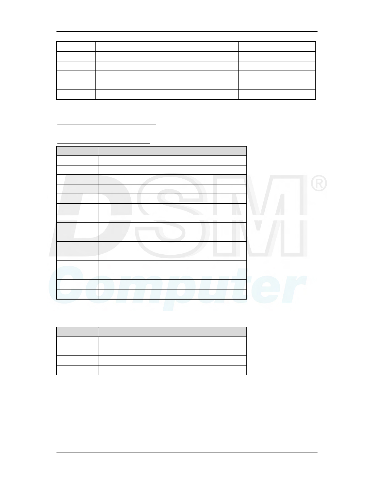
1.3 Product Specification
Main processor
- Intel® Core 2 Duo/Pentium D/Pentium® 4/Celeron D Processor
- FSB: 1,066/800/533MHz
BIOS
Phoenix (Award) system BIOS with 4Mb Flash ROM with easy upgrade function
ACPI, DMI, Green function and Plug and Play Compatible
Main Memory
- Support dual channel DDR2 memory interface
- Non-ECC, non-buffered DIMMs only
- Two DIMM sockets support 800/667/533 DDR2-SDRAM up to 4GB System
Memory
L2 Cache Memory
Built-in Processor
Chipset
Intel® Q965 GMCH and ICH8DO chipset
Bus Interface
- Follow PICMG 1.3 Rev 1.0 standard (PCI Express and PCI)
- Support four PCI Express x1 (can be aggregated as one PCI Express x4) through
backplane
- Support four PCI devices through backplane
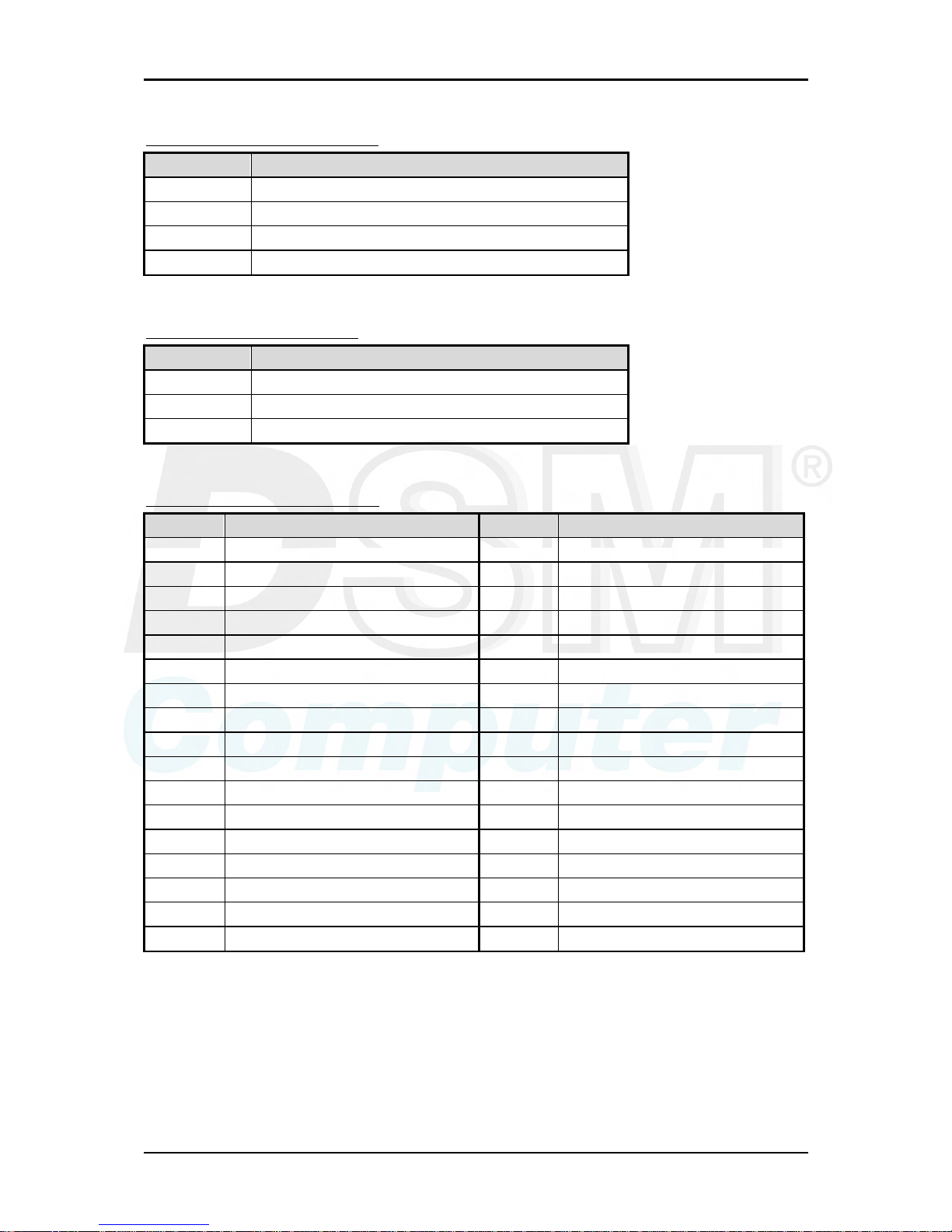
SATA
- Four SATA 300 ports on-board and dual SATA 300 ports via backplane
- Support Intel® Matrix Storage Technology based on Intel® ICH8DO
Floppy Drive Interface
Support one FDD port up to two floppy drives and 5-1/4"(360K, 1.2MB), 3-1/2"
(720K, 1.2MB, 1.44MB, 2.88MB) diskette format and 3-mode FDD
Serial Ports
Support two high-speed 16C550 compatible UARTs with 16-byte T/R FIFOs
Parallel Port
Support one parallel port with SPP, EPP and ECP modes
USB Interface
Support eight USB (Universal Serial Bus) ports (dual USB ports on bracket that
dedicated to keyboard & mouse; four USB ports on-board and dual USB ports via
backplane) for high-speed I/O peripheral devices
PS/2 Mouse and Keyboard Interface
Support one 10-pin connector for external PS/2 keyboard/mouse connection
Auxiliary I/O Interfaces
System reset switch, external speaker, Keyboard lock and HDD active LED, etc

System Overview
96M4321o User’s Manual 1-4
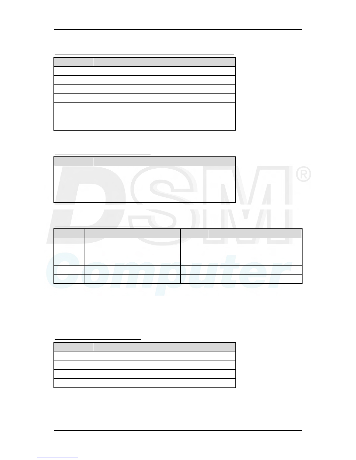
Real Time Clock/Calendar (RTC)
Support Y2K Real Time Clock/Calendar with battery backup for 7-year data
retention
Watchdog Timer
- Support WDT function through software programming for enable/disable and
interval setting
- Generate system reset
On-board VGA
GMCH integrated graphics, 400MHz core frequency; share system memory up to
64MB for system with greater than or equal to 192MB of system memory
On-board Ethernet LAN
Dual Intel® PCI Express x1 interface based Gigabit Ethernet to support RJ-45
connector
High Driving GPIO
Support 8 programmable high driving GPIO
Cooling Fans
Support one 4-pin power connector for CPU fan and one 3-pin power connector
for system fan
System Monitoring Feature
Monitor CPU temperature, system temperature and major power sources, etc.
Bracket
Support dual Ethernet port with 2 indicators, dual USB ports and one CRT port
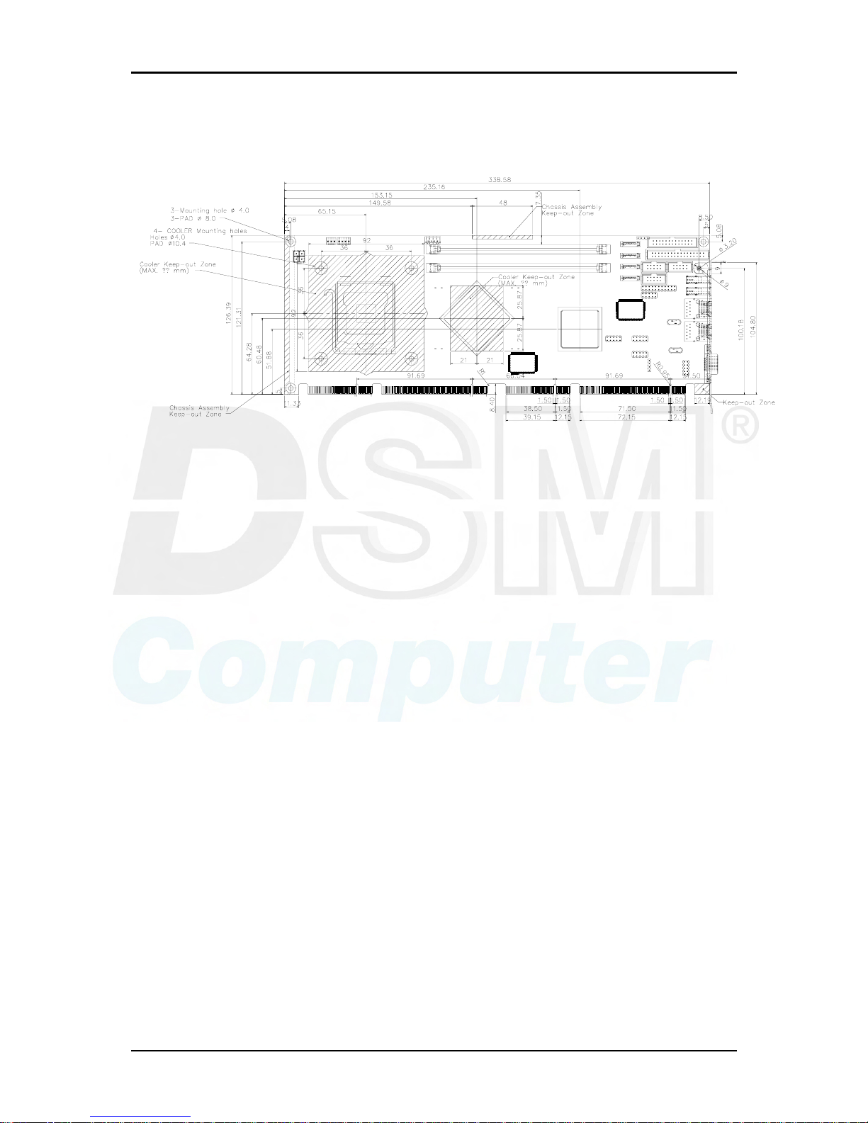
Outline Dimension (L X W):
338.5mm (13.33”) X 122mm (4.8”)
Power Requirements:
- +12V@ 3.4A
- +5V @ 4.5A
- Test configuration:
‧CPU: Intel® Core 2 Duo 2.13GHz(FSB: 1,066 / L2 cache: 2MB)
‧Memory: Transcend (SAMSUNG-K4T51083QC-ZCE7) 512GBx2 DDRII 800
‧Primary Master SATA HDD: HITACHI-HDS721680PLA380 (82GB)
‧OS: Microsoft Windows XP Professional + SP2
‧Test Programs: Burning Test V5.0
‧Run Time: Full loading
Operating Temperature:
0°C ~ 60°C (23°F ~ 140°F)
Storage Temperature:
-20°C ~ 80°C
Relative Humidity:
5% ~ 90%, non-condensing
System Overview
96M4321o User’s Manual 1-5
1.3.1 Mechanical Drawing
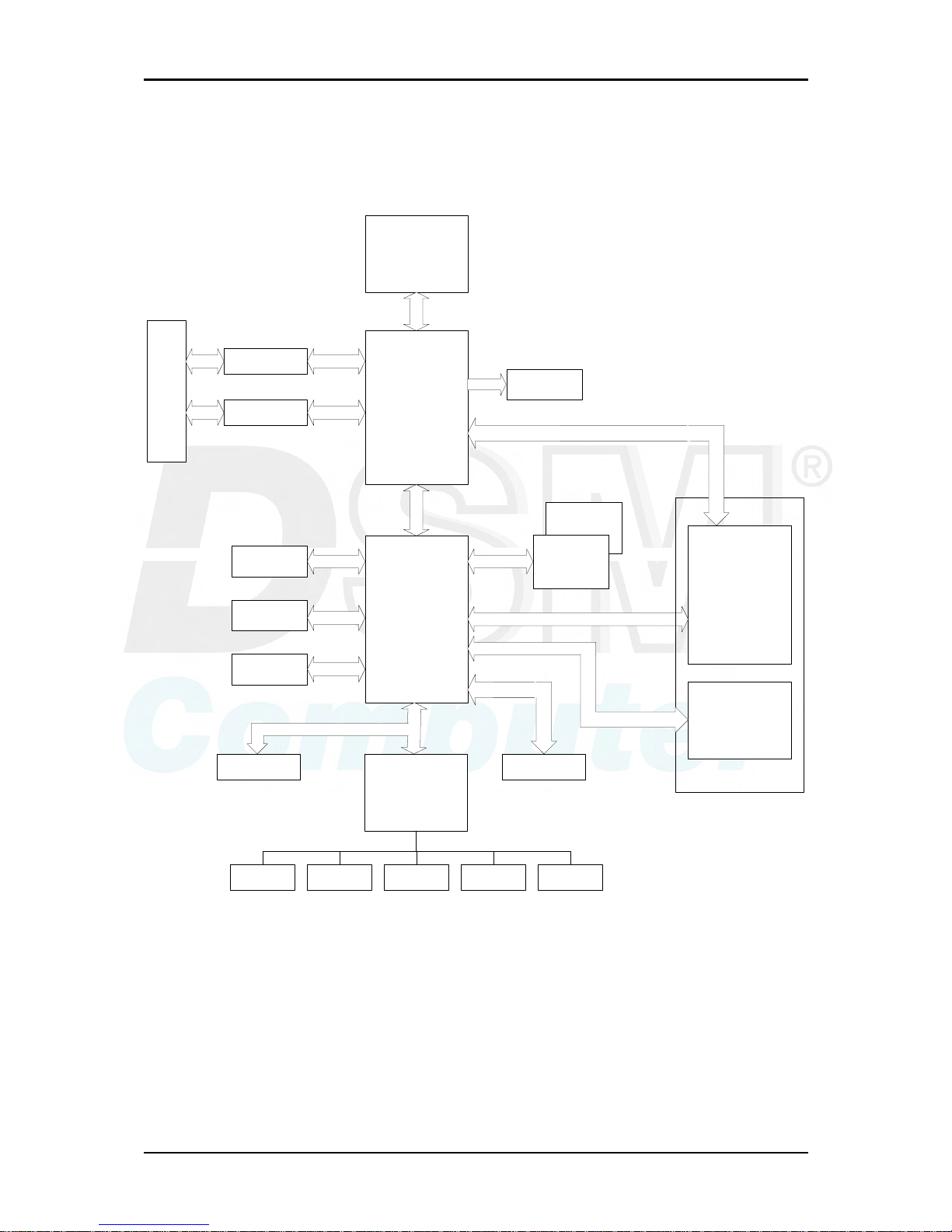
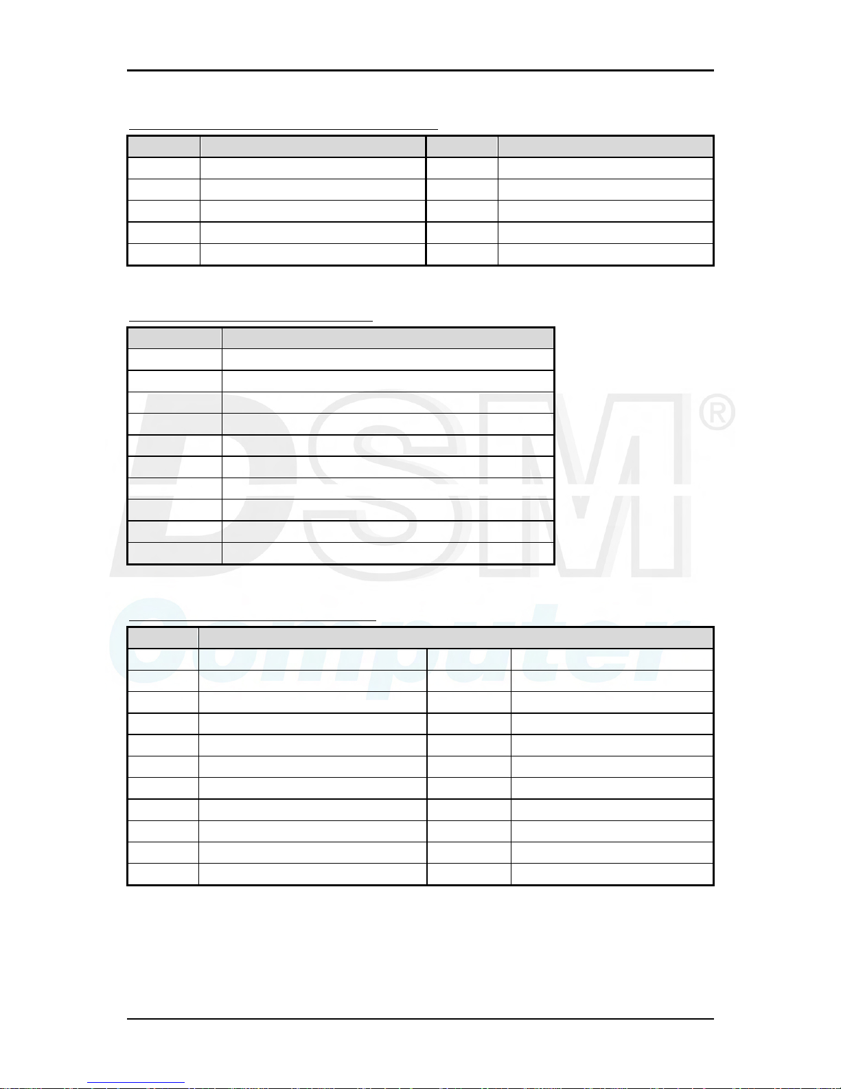
1.4 System Architecture
96M4321o adopts Intel® Q965 Express chipset that supports Intel® Core 2
Duo processor that based on Intel innovative Core Mircoarchitecture Technology.
Q965 GMCH (Graphics Memory Controller Hub) embedded Graphics Media
Accelerator 3000 (GMA 3000) and features PCI Express x16 graphics interface via
backplane that supports the latest high-performance graphics cards. Along with
the highest 1,066MHz FSB of processor, the parallel system memory up to DDR2 800
as well.
The companion I/O controller, ICH8DO has six PCI Express x1 links that
throughput is 2.5Gbps per direction. And they were designed as interface of dual
Gigabit Ethernet ports on-board and four PCI Express x1 expansion via backplane.
One special characteristic of the ICH8DO is the capability to aggregate these four
PCI Express x1 link as on PCI Express x4 link. And that is what user can benefit for
PCI Express x4, high throughput storage expansion card via backplane.
ICH8DO provides six SATA 300 ports, together with Intel® Matrix Storage
Technology (MST), the 96M4321o offers cost effective RAID 0, 1, 5 and 10
that seamlessly protects against data loss from hard drive failure. Dual SATA ports
and dual USB ports are routed to gold finger for better wiring consideration of these
two kinds of interface via backplane.
System Overview
96M4321o User’s Manual 1-6
Super I/O chip, W83627 is responsible for PS/2 keyboard/mouse, UARTs, FDC,
hardware monitor, Parallel, and Watch Dog Timer interface.
8237L
INTEL LAG775
P4 Processor
Q965
ICH8-R
ICH8-DO
ICH8
W83627EHG
HW
MONITOR
RS232 x2 KB/MS
DDR2 DIMM
CHANNEL A
DDR2 DIMM
CHANNEL B
DDR2 TERMINATOR
SATA CONN
x4
BIOS SPI ROM
USB PORT
x6
HD AUDIO
LPT GPIO
CRT-CONN
82566DM
DDR2 CHA
DDR2 CHB
PICMG 1.3
PICMG 1.3
PCI
PCIE BUS
USB BUS
HD LINK
RGB
PCI-E Bye 1 x 4
LPC BUS
SPI BUS
DMI x4 CPU BUS
PCI BUS
SPI BUS
SPI BUSPCI-E Bye 16 x 1
SATA BUS
96M4321o System Block Diagram
Hardware Configuration
96M4321o User’s Manual 2-1
Chapter 2
Hardware Configuration
This chapter gives the definitions and shows the positions of jumpers, headers and
connector. All of the configuration jumpers on 96M4321o series are in the
proper position. The default settings shipped from factory are marked with a star
(Ì).
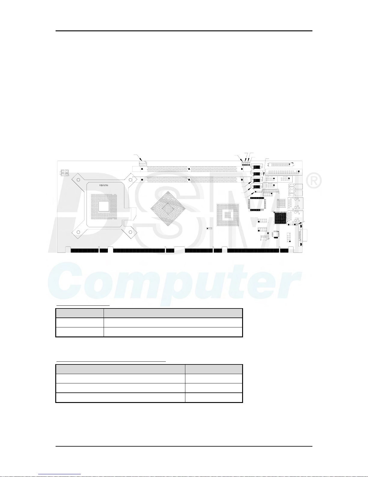
2.1 Jumper Setting
U14
J40
J17
J35
J41
J51
U56
J37
U55
J46
JP5
J43
J45
J36
J34
J53
J25
J47
J31
J32
J42
J27
J28
J49
U45
U28
JP4
U22
J10
J56
J57
J58
J50
J9
J21
J18
JP6
J54
J1
Figure 2-1 96M4321o Jumper Location
JP4: CMOS Clear
JP4 Function
1-2 Short Normal Operation Ì
2-3 Short Clear CMOS Contents
JP5: COM2 (J43) Interface Selection
JP5 Function
5-6, 9-11, 10-12, 15-17, 16-18 Short RS-232 Ì
3-4, 7-9, 8-10, 13-15, 14-16, 21-22 Short RS-422
1-2, 7-9, 8-10, 19-20 Short RS-485
Hardware Configuration
96M4321o User’s Manual 2-2
JP6: Intel 82573L Interface Selection
Reserve for Enable or disable LAN function.
Normal control at 1-2 short.
J56/J57: PCI-E X1,X4 Interface Selection
J56,J57 Function
Short PCI-E X4 (Support one slot)
Open PCI-E X1 (Support four slot) Ì
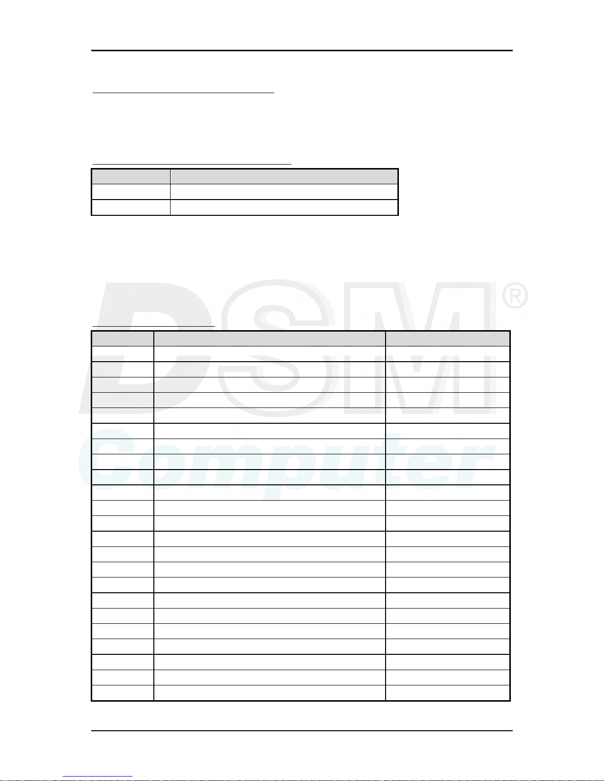
2.2 Connector Allocation
I/O peripheral devices are connected to the interface connectors on this Single Board
Computer.
Connector Function List
Connector Description Remark
J1 VGA D-SUB Connector
J9 FAN 1 (CPU FAN) Power Connector
J10 +12V Power Connector
J17 FAN 2 (SYSTEN FAN) Power Connector
J18 DDR2 SDRAM SLOT
J21 DDR2 SDRAM SLOT
J25 Floppy Connector
J27 SATA 3 Connector
J28 SATA 2 Connector
J31 SATA 0 Connector
J32 SATA 1 Connector
J34 External USB Connector
J35 Internal USB Connector
J36 External USB Connector
J37 Internal USB Connector
J40 Audio CD -IN Connector
J41 Audio Connector
J42 COM1 Serial Port 1 Connector
J43 COM2 Serial Port 2 Connector
J45 External PS/2 Keyboard/Mouse Connector
J46 General Purpose I/O Connector
J47 Parallel Port Connector
J49 External Speaker Connector
Hardware Configuration
96M4321o User’s Manual 2-3
J50 Suspend LED
J51 SATA LED
J53 Ethernet RJ-45 Connector (LAN 1)
J54 Ethernet RJ-45 Connector (LAN 2)
J55 Reserve
J58 Power LED
Pin Assignments of Connectors
J1: On-board VGA Connector
PIN No. Signal Description
1 Red
2 Green
3 Blue
4 Monitor ID0 (MONID0) (5V I/F)
5 Ground
6 Ground
7 Ground
8 Ground
9 +5V
10 Ground
11 Monitor ID1 (MONID1) (5V I/F)
12 VGA DDC Data (5V I/F)
13 Horizontal Sync. (HSYNC) (5V I/F)
14 Vertical Sync. (VSYNC) (5V I/F)
15 VGA DDC Clock (5V I/F)
J9: CPU Fan Connector
PIN No. Signal Description
1 Ground
2 +12V
3 Fan Control
4 Fan Speed Detecting signal
Hardware Configuration
96M4321o User’s Manual 2-4
J10: +12V POWER Connector
PIN No. Signal Description
1 Ground
2 Ground
3 +12V
4 +12V
J17: System Fan Connector
PIN No. Signal Description
1 Ground
2 +12V
3 Fan Speed Detecting signal
J25: FDC Interface Connector
PIN No. Signal Description PIN No.
Signal Description
1 Ground 2 Density Select 0
3 Ground 4 N/C
5 Ground 6 Density Select 1
7 Ground 8 Index#
9 Ground 10 Motor ENA#
11 Ground 12 Drive Select B#
13 Ground 14 Drive Select A#
15 Ground 16 Motor ENB#
17 Ground 18 Direction#
19 Ground 20 Step#
21 Ground 22 Write Data#
23 Ground 24 Write Gate#
25 Ground 26 Track 0#
27 Ground 28 Write Protect#
29 Ground 30 Read Data#
31 Ground 32 Head Select#
33 Ground 34 Disk Change#
Hardware Configuration
96M4321o User’s Manual 2-5
J31/J32/J28/J27: Primary/Secondary/3rd/4th SATA Connector
PIN No. Signal Description
1 Ground
2 SATATX+ (SATATXP)
3 SATATX- (SATATXN)
4 Ground
5 SATARX- (SATARXN)
6 SATARX+ (SATARXP)
7 Ground
J34/J36: External USB Connector
PIN No. Signal Description
1 5V Dual
2 USB03 USB0+
4 Ground
J35/J37: Internal USB Connector
PIN No. Signal Description PIN No.
Signal Description
1 Ground 2 5V Dual
3 Ground 4 USB3-
5 USB2+ 6 USB3+
7 USB2- 8 Ground
9 5V Dual 10 Ground
Note:
5V Dual is always available. It's supplied by either 5V VCC power source in normal
operation mode or 5V standby power source in standby mode.
J40: Audio CD-IN Connector
PIN No. Signal Description
1 CD-in Left Channel
2 CD Ground
3 CD Ground
4 CD-in Right Channel
Hardware Configuration
96M4321o User’s Manual 2-6
J41: Audio MIC/Line-in/Line-out Connector
PIN No. Signal Description PIN No.
Signal Description
1 MIC with Reference Voltage 2 Analog Ground
3 Line-in Left Channel 4 Analog Ground
5 Line-in Right Channel 6 Analog Ground
7 Line-out Left Channel 8 Analog Ground
9 Line-out Right Channel 10 N/C
J42: COM1 Serial Port 1 Connector
PIN No. Signal Description
1 DCD (Data Carrier Detect)
2 RXD (Receive Data)
3 TXD (Transmit Data)
4 DTR (Data Terminal Ready)
5 GND (Ground)
6 DSR (Data Set Ready)
7 RTS (Request to Send)
8 CTS (Clear to Send)
9 RI (Ring Indicator)
10 N/C
J43 : COM2 Serial Port 2 Connector
PIN No. Signal Description
RS-232 RS-422 RS-485
1 DCD (Data Carrier Detect) TX- DATA-
2 RXD (Receive Data) TX+ DATA+
3 TXD (Transmit Data) RX+ N/C
4 DTR (Data Terminal Ready) RX- N/C
5 GND (Ground) GND GND
6 DSR (Data Set Ready) N/C N/C
7 RTS (Request to Send) N/C N/C
8 CTS (Clear to Send) N/C N/C
9 RI (Ring Indicator) N/C N/C
10 N/C N/C N/C
Note:
J43 (COM2) could be configurable as RS-232/422/485 with jumper JP5.
Hardware Configuration
96M4321o User’s Manual 2-7
J45: External PS/2 Keyboard/Mouse Connector
PIN No. Signal Description PIN No.
Signal Description
1 Mouse Data 2 Keyboard Data
3 N/C 4 N/C
5 Ground 6 Ground
7 PS2 Power 8 PS2 Power
9 Mouse Clock 10 Mouse Clock
J46: General Purpose I/O Connector
PIN No. Signal Description PIN No.
Signal Description
1 GPIO0 2 GPIO4
3 GPIO1 4 GPIO5
5 GPIO2 6 GPIO6
7 GPIO3 8 GPIO7
9 Ground 10 +5V
Note:
All General Purpose I/O ports can only apply to standard TTL ± 5% signal level
(0V/5V), and each Fan.
J47: Parallel Port Connector
PIN No. Signal Description PIN No.
Signal Description
1 Strobe# 14 Auto Form Feed#
2 Data 0 15 Error#
3 Data 1 16 Initialization#
4 Data 2 17 Printer Select IN#
5 Data 3 18 Ground
6 Data 4 19 Ground
7 Data 5 20 Ground
8 Data 6 21 Ground
9 Data 7 22 Ground
10 Acknowledge# 23 Ground
11 Busy 24 Ground
12 Paper Empty 25 Ground
13 Printer Select 26 N/C
Hardware Configuration
96M4321o User’s Manual 2-8
J49: External Speaker Connector
PIN No. Signal Description
1 Speaker Signal Output (Open-drain w/
internal series 33 Ohm)
2 N/C
3 Ground
4 +5V
Note:
The pull-high voltage of external speaker is limited at 5V maximum.
J50: Suspend LED Connector
PIN No. Signal Description
1 Ground
2 5V_DUAL
J51: Suspend LED Connector
PIN No. Signal Description
1 SATA LED Signal
2 3.3V
J53/J54 : Ethernet RJ-45 Connector
PIN No. Signal Description
1 MDI0+ (MDI0P)
2 MDI0- (MDI0N)
3 MDI1+ (MDI1P)
4 MDI2+ (MDI2P)
5 MDI2- (MDI2N)
6 MDI1- (MDI1N)
7 MDI3+ (MDI3P)
8 MDI3- (MDI3N)
J58: Power LED Connector
PIN No. Signal Description
1 Ground
2 3.3V
System Installation
96M4321o User’s Manual 3-1
Chapter 3
System Installation
This chapter provides you with instructions to set up your system. The additional
information is enclosed to help you handle WDT and GPIO operation in software
programming.
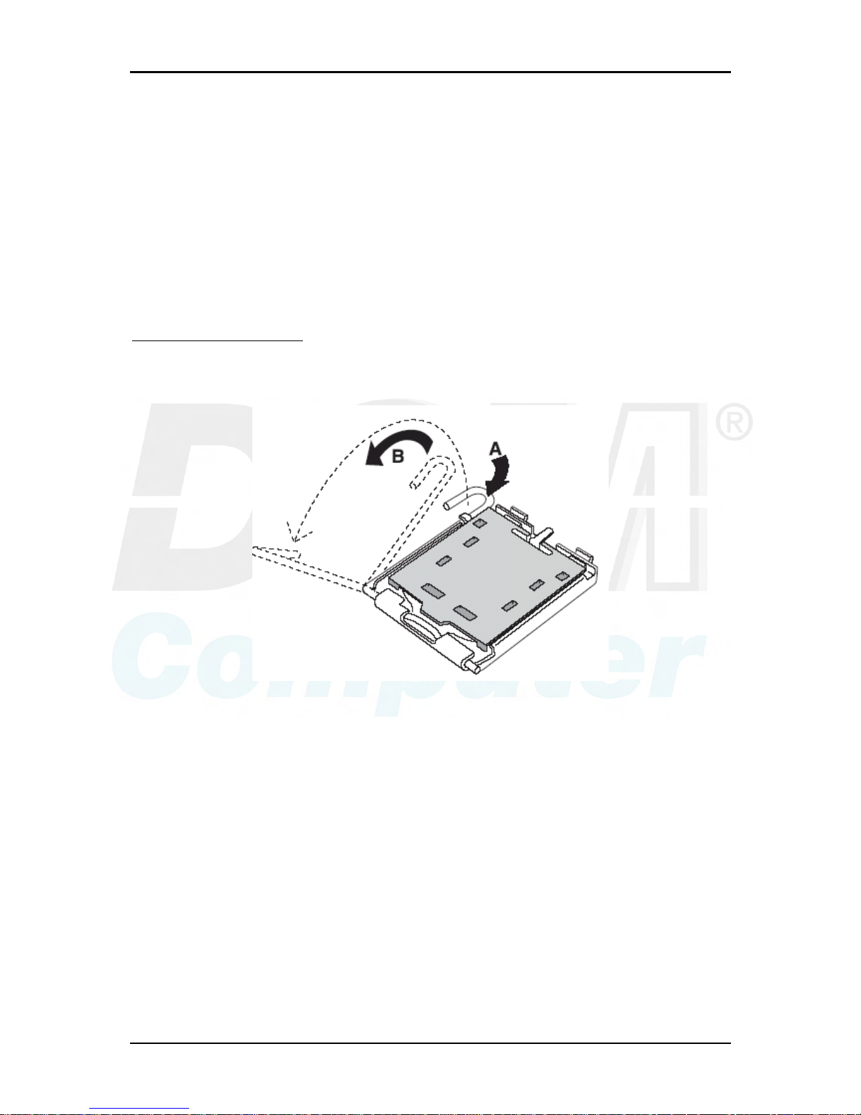
3.1 Intel® LGA775 Processor
Installing LGA775 CPU
1) Lift the handling lever of CPU socket outwards and upwards to the other end.
Following step A position to step B position.
Figure 3-1
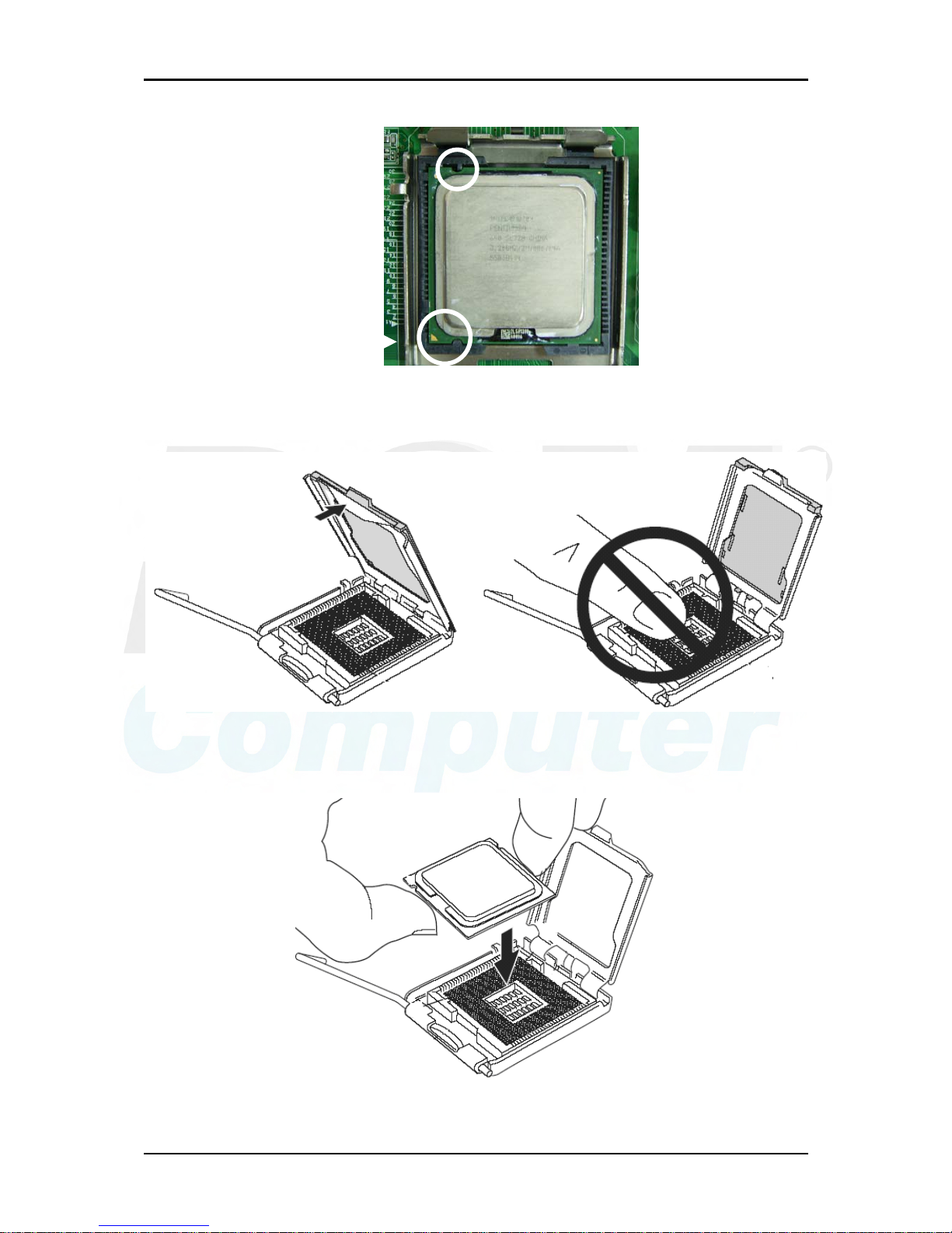
2) Aligning the processor’s pins with pinholes on the socket, and then make sure that
the notched corner or dot mark (pin 1) of the CPU corresponds to the socket’s
bevel end. Then press the CPU gently until it fits into correct place. If this
operation is not easy or smooth, don’t do it forcibly. You need to check and
rebuild the CPU pin uniformly.
System Installation
96M4321o User’s Manual 3-2
Figure 3-2
Figure 3-3
Figure 3-4
Triangle mark is meanin
g
first pin position; kindl
y
assemble and take aim at
notch of top and bottom
between CPU and socket.

System Installation
96M4321o User’s Manual 3-3
Precaution! (See fig.3-3 and fig.3-4) Don’t touch directly by your hand or impacts
internal align balls of CPU socket to avoid motherboard destruction, it is a precise
actuator.
3) Push down the lever to lock processor chip into the socket once CPU fits.
4) Follow the installation guide of cooling fan or heat sink to mount it on CPU
surface and lock it on the LGA775.
Removing CPU
1) Unlock the cooling fan first.
2) Lift the lever of CPU socket outwards and upwards to the other end.
3) Carefully lifts up the existing CPU to remove it from the socket.
4) Follow the steps of installing a CPU to change to another one or place handling
bar to close the opened socket.
Configuring System Bus
96M4321o will automatically detect the CPU used. All of CPU speed of
Intel® Pentium® D, Pentium® 4 and Celeron D can be detected automatically.
3.2 Main Memory
96M4321o provides two DDR2-SDRAM DIMM sockets to support dualchannel & single channel DDR2 memory interface. The maximum memory size can
be up to 4 GB, memory frequency includes 800/667/533. Auto detects memory
clock, which is according to BIOS CMOS settings.
For system compatibility and stability, do not use memory module without brand.
Memory configuration can be either one double-sided DIMM in either one DIMM
socket or two single-sided DIMM in both sockets.
Watch out the contact and lock integrity of memory module with socket, it will
impact on the system reliability. Follow normal procedures to install memory
module into memory socket. Before locking, make sure that all modules have been
fully inserted into the card slots.
Dual Channel DDR2 DIMMs
Dual Channel DDR2 memory technology doubles the bandwidth of memory bus.
Adequate or higher bandwidth of memory than processor would increase system
performance. To enable Dual Channel DDR2 memory technology, install two
identical memory modules in both memory sockets is required. Following tables
show bandwidth information of different processor and memory configurations.
 Loading...