

DSM Computer AG 96M4281o User Manual

96M4281o
Single Board Computer
User's Manual
Version 1.0
Copyright © DSM Computer AG, 2008. All rights reserved.
All other brand names are registered trademarks of their respective owners.

Preface
Table of Contents
How to Use This Manual
Chapter 1 System Overview.......................................................................................................1-1
1.1 Introduction.................................................................................................................................. 1-1
1.1.1 Mechanical Drawing......................................................................................................... 1-5
1.2 System Architecture .................................................................................................................... 1-6
Chapter 2 Hardware Configuration ...........................................................................................2-1
2.1 Jumper Setting ............................................................................................................................. 2-1
2.2 Connector Allocation .................................................................................................................. 2-3
Chapter 3 System Installation....................................................................................................3-1
3.1 Yonah/Merom Process
or........................................................................................................... 3-1
3.2 Main Memory .............................................................................................................................. 3-3
3.3 Clear CMOS Op
eration............................................................................................................... 3-4
3.4 WDT Function.............................................................................................................................. 3-4
3.5 GPIO.............................................................................................................................................. 3-6
Chapter 4 BIOS Setup Information............................................................................................4-1
4.1 Entering Setup.............................................................................................................................. 4-1
4.2 Main Menu ...................................................................................................................................4-2
4.3 Standard CMOS Setup Menu .................................................................................................... 4-3
4.4 IDE Adaptors Setup Menu......................................................................................................... 4-5
4.5 Advanced BIOS Feature ............................................................................................................. 4-6
4.6 CPU Feature ................................................................................................................................. 4-7
4.7 Hard Disk Boot Priority.............................................................................................................. 4-8
4.8 Advanced Chipset Feature....................................................................................................... 4-12
4.9 Integrated Peripherals .............................................................................................................. 4-15
4.10 Power Management Setup ..................................................................................................... 4-21
4.11 PnP/PCI Configurations ........................................................................................................ 4-25
4.12 PC Health Status...................................................................................................................... 4-27
4.13 Default Menu ........................................................................................................................... 4-28
4.14 Supervisor/User Password Setting ...................................................................................... 4-29
4.15 Exiting Selection
...................................................................................................................... 4-30
Chapter 5 Troubleshooting........................................................................................................5-1
5.1 Hardware Quick Installation ..................................................................................................... 5-1
5.2 Frequency Asking Questions................................................................................................... 5-10
5.3 BIOS Setting................................................................................................................................ 5-10
Appendix A
Appendix B

How to Use This Manual
The manual describes how to configure your 96M4281o system to meet various
operating requirements. It is divided into five chapters, with each chapter
addressing a basic concept and operation of Single Board Computer.
Chapter 1 : System Overview. Presents what you have in the box and give you an
overview of the product specifications and basic system architecture for this series
model of single board computer.
Chapter 2 : Hardware Configuration. Shows the definitions and locations of
Jumpers and Connectors that you can easily configure your system.
Chapter 3 : System Installation. Describes how to properly mount the CPU, main
memory and Compact Flash to get a safe installation and provides a programming
guide of Watch Dog Timer function.
Chapter 4 : BIOS Setup Information. Specifies the meaning of each setup
parameters, how to get advanced BIOS performance and update new BIOS. In
addition, POST checkpoint list will give users some guidelines of trouble-shooting.
Chapter 5 : Troubleshooting. Provides various useful tips to quickly get 96M4281o
running with success. As basic hardware installation has been addressed in Chapter
3, this chapter will basically focus on system integration issues, in terms of backplane
setup, BIOS setting, and OS diagnostics.
The content of this manual is subject to change without prior notice. These changes
will be incorporated in new editions. DSM Computer AG may make supp-
lement or change in the products described in this document at any time.
Updates to this manual, technical clarification, and answers to frequently asked
questions will be shown on the following web site :
http://www.DSM.AG.

System Overview
96M4281o User’s Manual 1-1
Chapter 1
System Overview
1.1 Introduction
96M4281o, PICMG 1.0 SBC (Slot Board Computer) is designed with Intel® Core™
Duo / Core™2 Duo / Core™ Solo processors with a 533/667MHz front side bus. It
adopts Intel® 82945GME Graphics Memory Controller Hub and the Intel® ICH7-M
DH I/O Controller Hub. The Mobile Intel® 945GME Express chipset's low power
design enables less average power consumption compared to previous generations.
The Intel 82945GME and ICH7-M DH delivers outstanding system performance
through high-bandwidth interface such as dual–channel DDR2 667/533 DIMM
sockets up to 4GB, and two Serial ATA high-speed data transferring at up to
1.5Gb/s. Dual Gigabit Ethernet ports offer PCI Express x1 based 10/100/1000
Ethernet connection for fast networking access. Additionally, the new Intel®
Graphics Media Accelerator 950 graphics core is also built into the Mobile Intel®
945GME chipset which provides excellent graphics performance over the previous
generation chipset. Other features include two serial ports, 8 USB 2.0, watchdog
timer, and hardware monitoring function.
In addition, 96M4281o, together with Intel® Matrix Storage Technology, it adds
support for RAID 0, 1 level providing quick access to data and protection against
data loss for maximum performance, protection and upgradeability.
96M4281o features:
Support Intel® Core Duo, Core 2 Duo, Core Solo processor with 667/533MHz
Front Side Bus
Dual 240-pin DDR2 SDRAM DIMM socket, support for DDR2 800/667
DIMMs, up to 4GB system memory ( ~3,2GB usable for OS)
Intel® 945GME integrated GMA 950 technology offer performance graphics
Equipped dual Intel 82573L Gigabit Ethernet ports
Support CRT, LVDS and optional DVI on board
Dual Gigabit Ethernet ports that based on PCI Express x1 interface without
sharing bandwidth of PCI expansion bus
Support RAID function (RAID 0, 1)

System Overview
96M4281o User’s Manual 1-2
1.2 Check List
The 96M4281o package should cover the following basic items:
One 96M4281o Industrial Mainboard
One SATA cable
One IDE cable
One LPT cable w/ bracket
One FDD cable
One DVI cable
One two ports Serial cable w/ bracket
One USB cable w/ bracket
One KB/MS Y cable
One 4-pin ATX power cable
If any of these items is damaged or missing, please contact your vendor and keep all
packing materials for future replacement and maintenance.
1.3 Product Specification
Main processor
CPU & Package: Intel® Core Duo/ Core Solo/ Core 2 Duo (Merom) processor
FSB: 667/533MHz
BIOS
Phoenix (Award) system BIOS with 8Mb Flash ROM
Main Memory
- Support dual-channel & signal channel DDR2 memory interface
- Non-ECC and non-buffered
- Up to 4GB DDR2 667/533 SDRAM on two 240pin DIMM sockets
L2 Cache Memory
Built in processor
Chipset
Intel 945GME and ICH7-M DH chipset
Bus Interface
- Follow PICMG 1.0 Rev 2.0 standard (32-bit PCI and 16-bit ISA)
- Fully complies with PCI Local Bus specification V2.2 (support 4 master PCI
slots)
PCI IDE Interface
Support one Ultra DMA100 IDE port

System Overview
96M4281o User’s Manual 1-3
SATA Interface
Two SATA 1.5Gb ports
Serial Ports
Support two serial ports, (RS-232x1, One RS-232/422/485 selectable)
Floppy Drive Interface
Support one FDD port up to two floppy drives and 5-1/4"(360K, 1.2MB), 3-1/2"
(720K, 1.2MB, 1.44MB, 2.88MB) diskette format and 3-mode FDD
Parallel Port
Support one parallel port
USB Interface
Support eight USB (Universal Serial Bus) ports on-board for high-speed I/O
peripheral devices.
PS/2 Mouse and Keyboard Interface
Support one 6-pin mini-DIN connector at rear I/O panel for PS/2
keyboard/mouse
Audio Interface
- Realtek ALC655 5.1 channel Audio
- Connector and header of Line-in/Line-out/MIC for external and internal usage
Auxiliary I/O Interfaces
System reset switch, external speaker, Keyboard lock and HDD active LED, etc
Real Time Clock/Calendar (RTC)
Support Y2K Real Time Clock/Calendar with battery backup for 7-year data
retention
Watchdog Timer
- Support WDT function through software programming for enable/disable and
interval setting
- Generate system reset
CompactFlash
- True IDE mode, compatibles with the ATA/ATAPI-4 specification
- One Type II CF socket on secondary IDE channel
External Interface
Support one Mini PCI interface
On-board VGA
- GMCH integrated GMA 950
- Share system memory up to 224MB for system memory
- Support LVDS interface
- Support optional DVO to DVI interface
On-board Ethernet LAN
Dual Gigabit (10/100/1000 Mbits/sec) LAN port using the Intel 82573L Gigabit
Ethernet Controller

System Overview
96M4281o User’s Manual 1-4
High Driving GPIO
Support 8-bit programmable high driving GPIO
Cooling Fans
Support one 4-pin power connector for CPU cooler and one 3-pin power
connector for system fan
System Monitoring Feature
Monitor CPU temperature, system temperature and major power sources, etc
Bracket
Support dual Ethernet port with 2 indicators, one MINI-DIN 6 PS/2 KB/MS port
and one CRT port
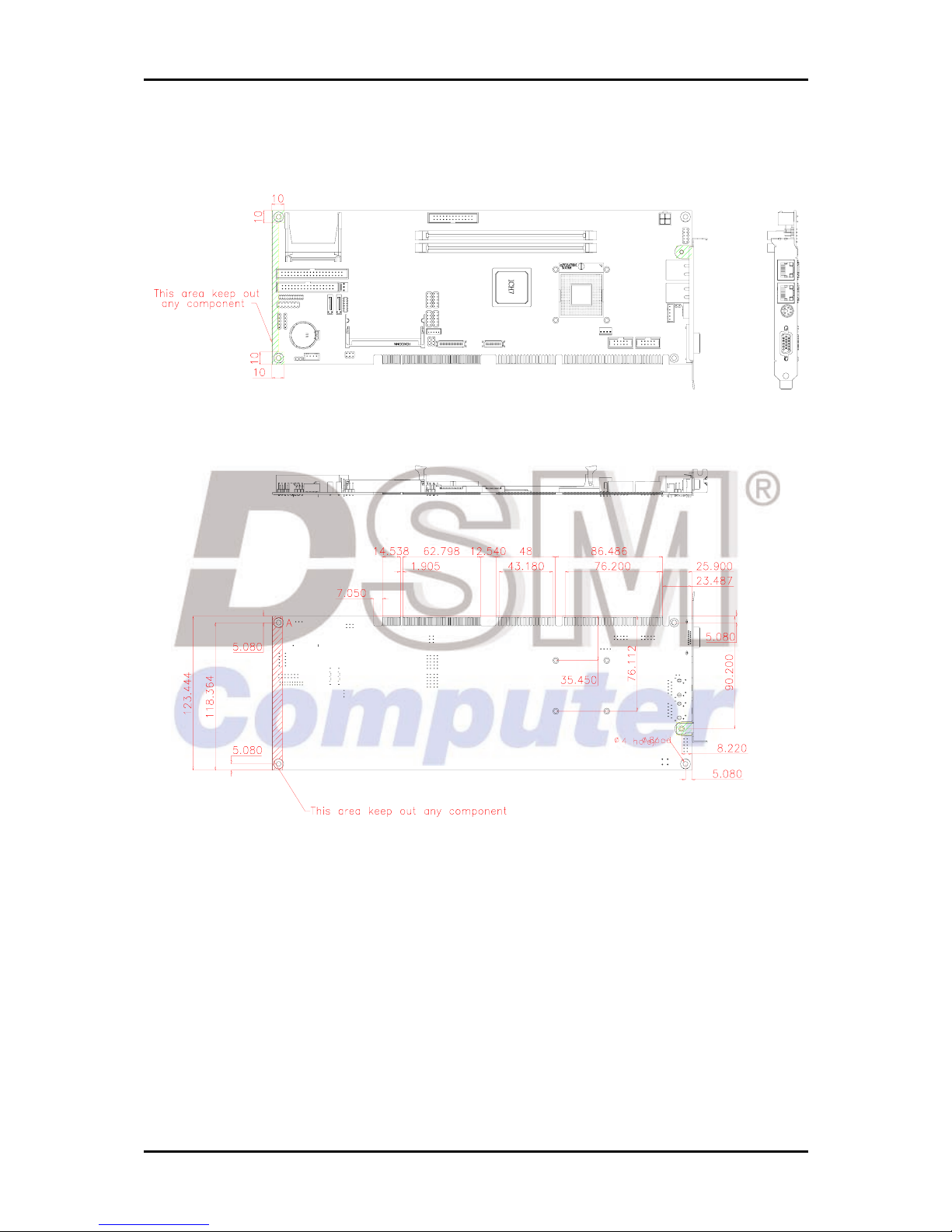
Outline Dimension (L X W):
338.5mm (13.33”) X 122mm (4.8”)
Power Requirements:
Configuration:
- +12V (CPU) @2.2A
- +12V (System) @1.1A
- +5V (System) @ 5.31A
- Test configuration:
‧CPU: Intel®Core™2 CPU T7200 2.0MHz (166*12) FSB:667MHz L2:4096K
‧Memory: Transcend 2GB DDR2 667(SAMSUNG K4T1G0840A-ZCE6)
‧HDD: Seagate ST380817AS 80G
‧OS: Windows 2000 Pro
‧Test Programs: BurnIn Test V4.0
‧Connected Fans: Only CPU fan connected
‧ Run Time: 30 minutes
Operating Temperature:
0°C ~ 55°C
Storage Temperature:
-20°C ~ 80°C
Relative Humidity:
0% ~ 95%, non-condensing
System Overview
96M4281o User’s Manual 1-5
1.3.1 Mechanical Drawing

System Overview
96M4281o User’s Manual 1-6
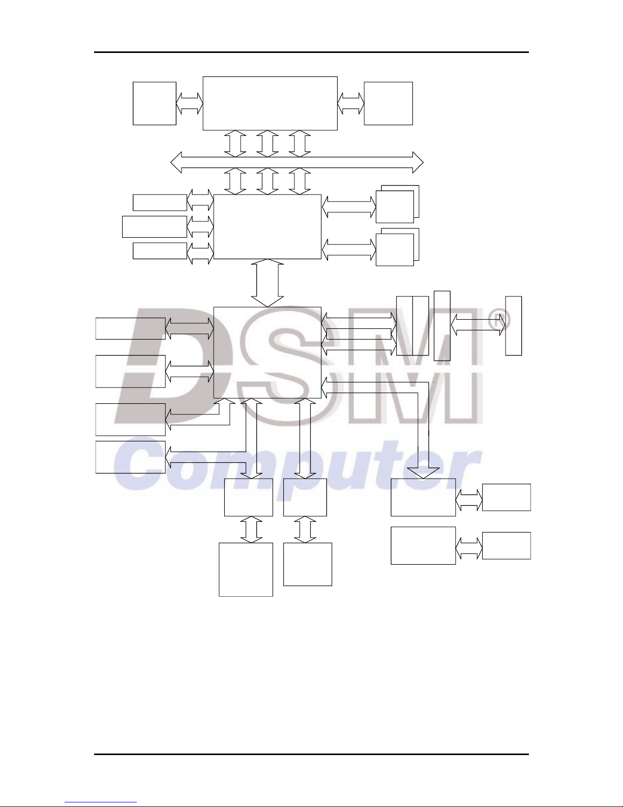
1.4 System Architecture
96M4281o includes Intel 945GME PCI Express chipset, Intel 82573L PCI Express x1
interface Gigabit Ethernet controller and Winbond Super I/O.
The 945GME chipset supports the latest Intel Core Duo/ Core Solo processors with
667/533MHz front side bus; integrated GMA950 that cover CRT, LVDS and
additional display interface - DVI. Up to 4GB DDR2 667/533 system memory in dual
DIMM sockets; one CF socket; one Mini PCI socket; two 1.5Gb SATA ports; one
Ultra DMA 100 IDE port; and eight USB 2.0 on 96M4281o.
W83628G is a PCI-to ISA bus conversion IC and W83629G is a condensed centralizes
IC for IRQ and DMA control, together form a completed set for the PCI-to-ISA
Bridge.
Winboard Super I/O W83627THG provides connection of PS/2 interface keyboard
& mouse; dual serial port; one parallel port; IrDA and GPIO interface.
System Overview
96M4281o User’s Manual 1-7
VGA Connector
DVO to DVI
RJ45
Giga
LAN
Intel 82573L
PCI CNTRL
AC' 9 7
ALC6 55
A
D
D
R
M
I
N
I
P
C
I
C
O
N
N
.
USB PO RT x8
Intel 82573L
FirmWare Hub
LAN
SATA x2
LPC
D
A
T
A
PCI ADDR/DATA
FCPGA-478
MIC IN
IDE Primary & CF
LINE IN
USB
RJ45
Giga
RS-232
Parallel
D
A
T
A
D
M
I
P
C
I
E
X
4
A
D
D
R
Floopy
C
T
R
L
LINE OUT
UDMA/100
C
T
R
L
Super I/O
83627THG
KB/MS
ICH7M/ICH7M-DH
SATA/1.5Gb
P
I
C
M
G
_
P
C
I
DDR2-533/667
DIMM
DDR2-533/667
IrDA
CHANNEL B
CHANNEL A
DIMM
P
C
I
t
o
I
S
A
B
r
i
d
g
e
ISA
LVDS
82801GM/GR
P
I
C
M
G
_
I
S
A
PCI EXPRESS By 1 x2
CK_410M
AGTL+ BUS
IMVP-VI
FSB 533/667
GMCH
82945GME
96M4281o Block Diagram
Hardware Configuration
96M4281o User’s Manual 2-1
Chapter 2
Hardware Configuration
This chapter gives the definitions and shows the positions of jumpers, headers and
connector. All of the configuration jumpers on 96M4281o are in the proper
position. The default settings shipped from factory are marked with a star (Ì).
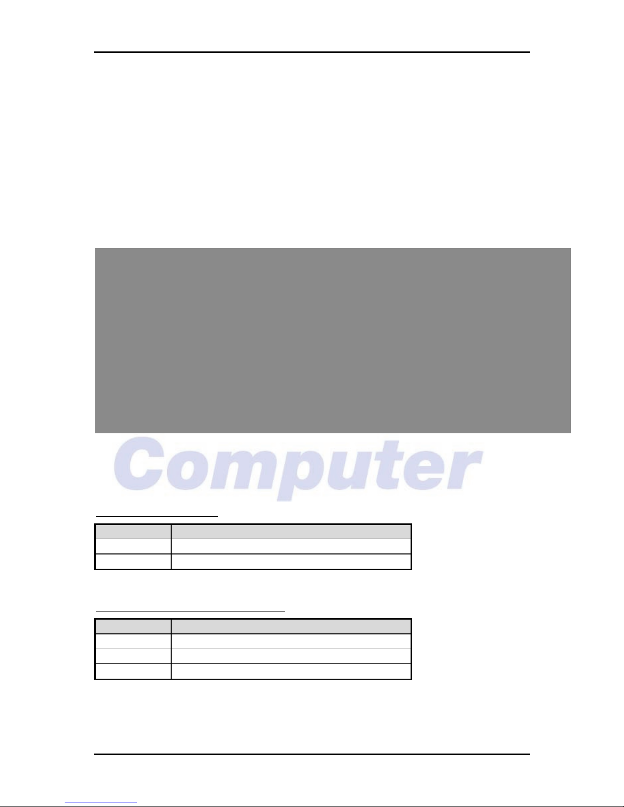
2.1 Jumper Setting
Figure 2-1 96M4281o Jumper & Connector Location
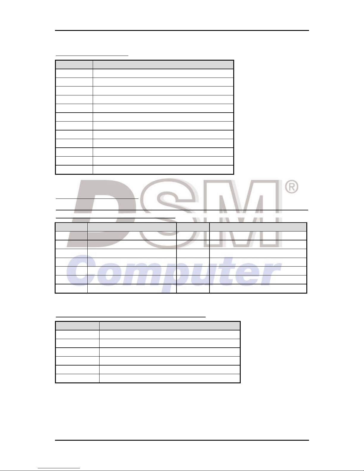
JP2 : CF mode selection
JP2 Function
1-2 Slave Mode
2-3 Master Mode Ì
JP3 : COM2 RS232/485/422 Selection
JP3 Function
RS232 5-6,9-11,10-12,15-17,16-18 Ì
RS485 1-2,7-9,8-10,19-20
RS422 3-4,7-9,8-10,13-15,14-16,21-22
Hardware Configuration
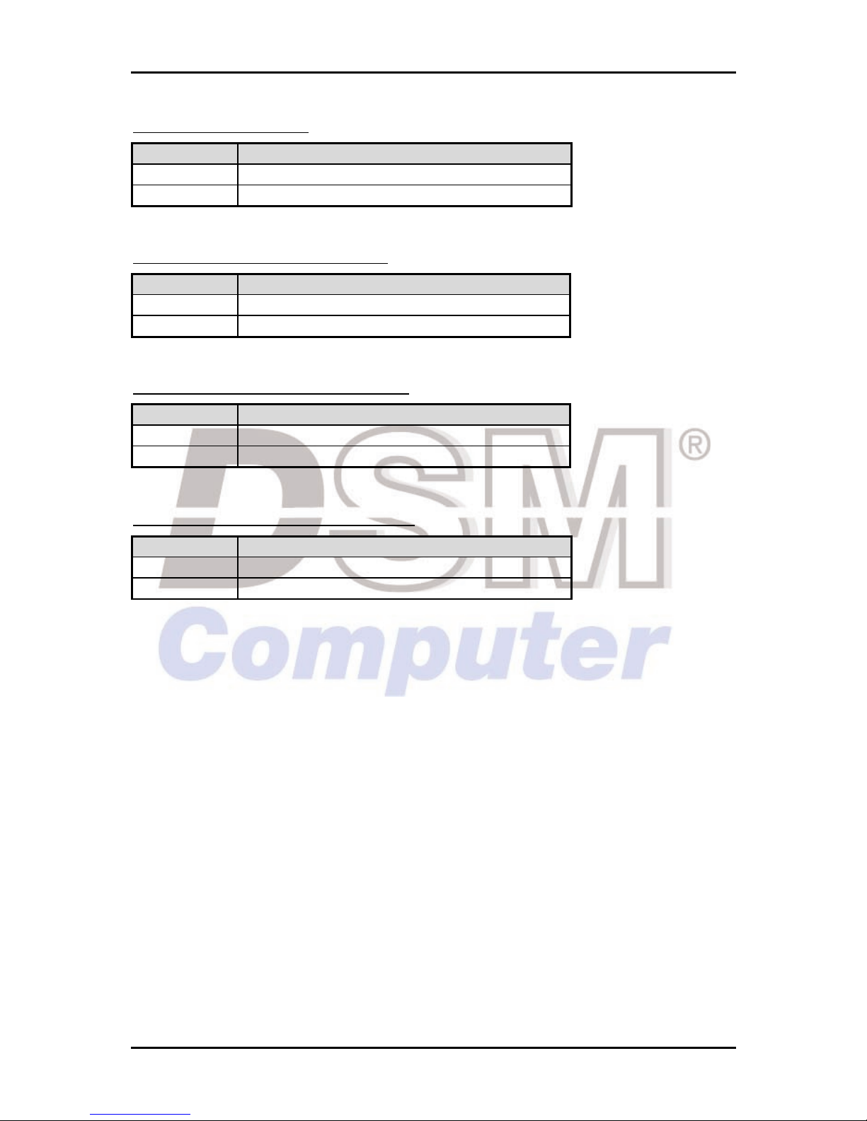
96M4281o User’s Manual 2-2
JP4 : LVDS Power Level
JP4 Process Selection
1-2 3.3V Ì
2-3 5V
JP5 : LVDS Back-light Power Level
JP5 Process Selection
1-2 3.3VÌ
2-3 5V
JP6 : AT/ATX Power Supply Selection
JP6 Process Selection
3-5, 4-6 ATX Power Supply Ì
1-3, 2-4 AT Power Supply
JP7 : RTC CMOS Clear Jumper Setting
JP7 Function
1-2 Normal Operation Ì
2-3 Clear CMOS Contents

Hardware Configuration
96M4281o User’s Manual 2-3
2.2 Connector Allocation
Figure 2-2 96M4281o Jumper & Connector Location
Hardware Configuration
96M4281o User’s Manual 2-4
Pin Assignments of Connectors
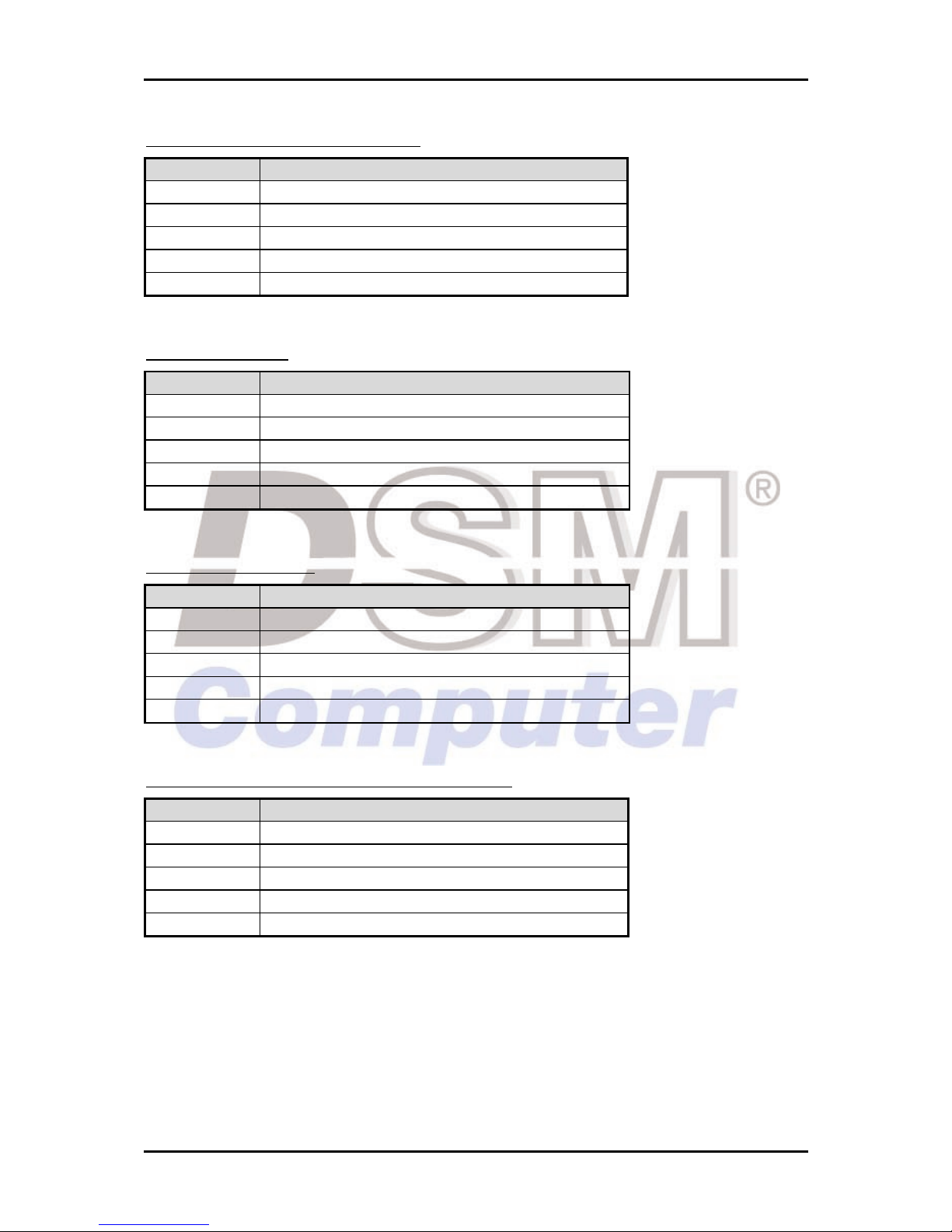
J1 : 4P Power Connector for CPU POWER 12V
1
2
3
4
PIN No. Signal Description
1 Ground
2 Ground
3 +12V
4 +12V
J2 : Parallel Port Connector
PIN No. Signal Description PIN No.
Signal Description
1 Strobe# 14 Auto form Feed#
2 Data 0 15 Error#
3 Data 1 16 Initialization#
4 Data 2 17 Printer Select IN#
5 Data 3 18 Ground
6 Data 4 19 Ground
7 Data 5 20 Ground
8 Data 6 21 Ground
9 Data 7 22 Ground
10 Acknowledge# 23 Ground
11 Busy 24 Ground
12 Paper Empty 25 Ground
13 Printer Select 26 N/C
J4 : Audio Header
PIN No. Signal Description
1 MIC Power
2 AGND
3 LINE IN Left
4 AGND
5 LINE IN Right
6 AGND
7 LINE OUT Left
8 AGND
9 LINE OUT Right
Hardware Configuration
96M4281o User’s Manual 2-5
J5 : Compact Flash Socket
PIN No. Signal Description PIN No.
Signal Description
1 Ground 2 Data 3
3 Data 4 4 Data 5
5 Data 6 6 Data 7
7 SDCS#0 8 Ground
9 Ground 10 Ground
11 Ground 12 Ground
13 +5V 14 Ground
15 Ground 16 Ground
17 Ground 18 SA2
19 SA1 20 SA0
21 Data 0 22 Data 1
23 Data 2 24 NC
25 NC 26 NC
27 Data 11 28 Data 12
29 Data 13 30 Data 14
31 Data 15 32 SDCS#3
33 Ground 34 IOR#
35 IOW# 36 WE#
37 INT 38 +5V
39 Ground 40 NC
41 RESET# 42 IORDY
43 NC 44 REQ
45 IDEACT# 46 PDIAG#
47 Data 8 48 Data 9
49 Data 10 50 Ground
J7 : CD-IN Header
PIN No. Signal Description
1 CD-L
2 CDGND
3 CDGND
4 CD-R
J8/J19 : LAN LED Pin Header
PIN No. Signal Description
1 LED+
2 LED-
Hardware Configuration
96M4281o User’s Manual 2-6
J9/J13 : Ethernet RJ-45 Interface Connector
PIN No. Signal Description
1 MDI_2P
2 MDI_0P
3 MDI_0N
4 +1.8V
5 MDI_2N
6 MDI_3P
7 GND
8 MDI_1P
9 MDI_1N
10 MDI_3N
11 ACT#
12 LINK#
13 LINK100#
14 LINK1000#
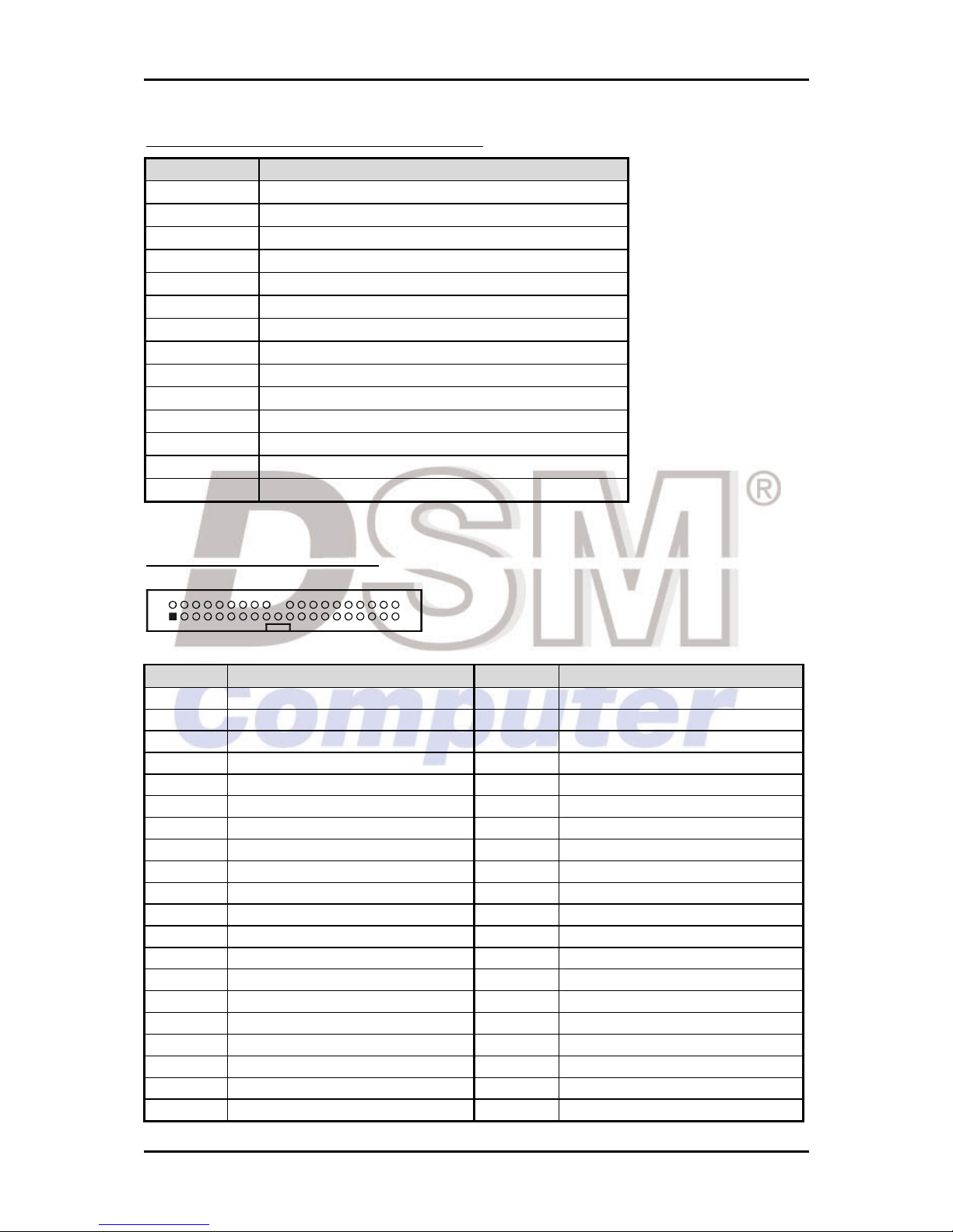
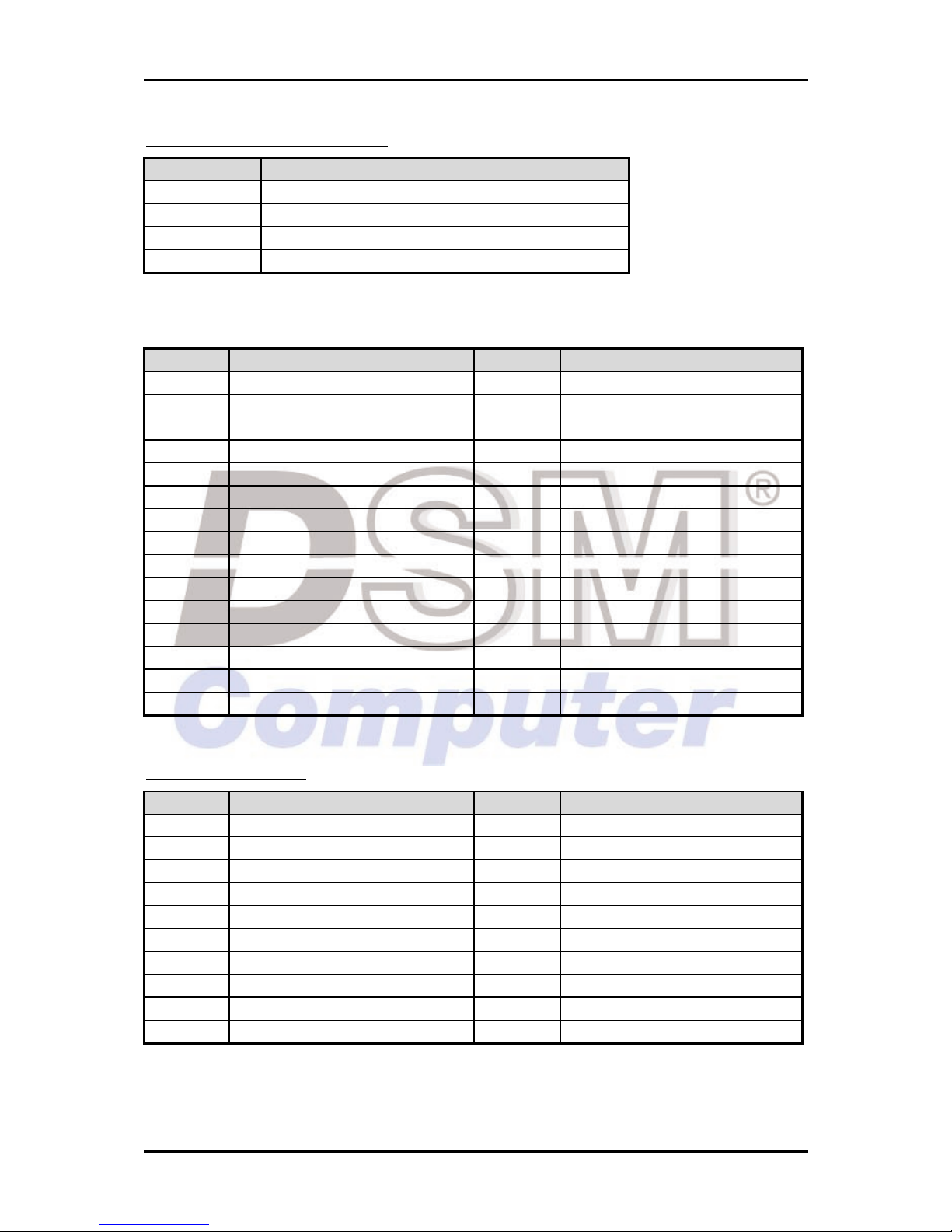
J10 : IDE Interface Connector
1
2
39
40
PIN No. Signal Description PIN No.
Signal Description
1 RESET# 2 Ground
3 Data 7 4 Data 8
5 Data 6 6 Data 9
7 Data 5 8 Data 10
9 Data 4 10 Data 11
11 Data 3 12 Data 12
13 Data 2 14 Data 13
15 Data 1 16 Data 14
17 Data 0 18 Data 15
19 Ground 20 N/C
21 DMA REQ 22 Ground
23 IOW# 24 Ground
25 IOR# 26 Ground
27 IOCHRDY 28 Pull-down
29 DMA ACK# 30 Ground
31 INT REQ 32 N/C
33 SA1 34 N/C
35 SA0 36 SA2
37 HDC CS0# 38 HDC CS1#
39 HDD Active# 40 Ground
Hardware Configuration
96M4281o User’s Manual 2-7
J11 : 3P FAN Power Connector
123
PIN No. Signal Description
1 Ground
2 +12V
3 Fan Speed Detecting signal
J12: FDD Interface Connector
PIN No. Signal Description PIN No.
Signal Description
1 Ground 2 DRVDEN0
3 Ground 4 NC
5 Ground 6 LPC_SMI#
7 Ground 8 INDEX#
9 Ground 10 MOA#
11 Ground 12 N/C
13 Ground 14 DSA#
15 Ground 16 N/C
17 Ground 18 DIR#
19 Ground 20 STEP#
21 Ground 22 WD#
23 Ground 24 WE#
25 Ground 26 TRAK0#
27 Ground 28 WPT#
29 N/C 30 RDATA#
31 Ground 32 HEAD#
33 N/C 34 DSKCJG#
J14/J15/J24/J25 : Dual Port USB Header
1
2
7
10
PIN No. Signal Description PIN No.
Signal Description
1 +5V 2 +5V
3 USBDATA- 4 USBDATA-
5 USBDATA+ 6 USBDATA+
7 Ground 8 Ground
10 NC
Hardware Configuration
96M4281o User’s Manual 2-8
J18 : 8-Bit GPIO Header
PIN No. Signal Description
1 Ground
2 Ground
3 GPIO1
4 GPIO5
5 GPIO2
6 GPIO6
7 GPIO3
8 GPIO7
9 GPIO4
10 GPIO8
11 +5V
12 +12V
J20 : Miscellaneous Header
(Pin1-3 : HDD LED. Pin2-4-6 : Power LED, Pin5-7: Reset Button, Pin11-13: Power
Button, Pin8-10-12-14: Speaker Header)
PIN No. Signal Description PIN No.
Signal Description
1 HDD LED+ 2 POWER LED+
3 HDD LED- 4 N/C
5 RESET BUTTON + 6 POWER LED7 RESET BUTTON - 8 SPEAKER +
9 10 N/C
11 POWER BUTTON + 12 N/C
13 POWER BUTTON - 14 SPEAKER -
J21 : Keyboard & Mouse Connector (Mini DIN 6)
PIN No. Signal Description
1 Keyboard DATA
2 Mouse DATA
3 Ground
4 +5V
5 Keyboard Clock
6 Mouse Clock
Hardware Configuration
96M4281o User’s Manual 2-9
J22 : External Keyboard Connector
PIN No. Signal Description
1 +5V
2 Ground
3 N/C
4 Keyboard Data
5 Keyboard Clock
J26 : IrDA Header
PIN No. Signal Description
1 +5V
2
3 IRRX
4 Ground
5 IRTX
J27 : SM BUS Header
PIN No. Signal Description
1 SM BUS Clock
2
3 Ground
4 SM BUS DATA
5 +3VSB
J28 : LVDS Panel Back-light Power Connector
PIN No. Signal Description
1 Backlight Power (select by JP5)
2 Ground
3 +12V
4 Ground
5 +5V
Hardware Configuration
96M4281o User’s Manual 2-10
J29 : 4P FAN Power Connector
PIN No. Signal Description
1 Ground
2 +12V
3 Fan Speed Detecting signal
4 Fan Speed Control signal
J30 : LVDS Panel Connector
PIN No. Signal Description PIN No.
Signal Description
1 LVDSA_DATA0 2 LVDSA_DATA0#
3 LVDSA_DATA1 4 LVDSA_DATA1#
5 LVDSA_DATA2 6 LVDSA_DATA2#
7 N/C 8 N/C
9 LVDSA_CLKP 10 LVDSA_CLKN
11 LVDSB_DATA0 12 LVDSB_DATA0#
13 LVDSB_DATA1 14 LVDSB_DATA1#
15 LVDSB_DATA2 16 LVDSB_DATA2#
17 N/C 18 N/C
19 LVDSB_CLKP 20 LVDSB_CLKN
21 LCTLB_DATA 22 LBKLT_CTL
23 Ground 24 LVDSB_DATA3#
25 Ground 26 Ground
27 VDD_LVDS 28 VDD_LVDS
29 N/C 30 VDD_LVDS
J32 : DVI Connector
PIN No. Signal Description PIN No.
Signal Description
1 TMDS_DATA0- 2 TMDS_DATA0+
3 Ground 4 Ground
5 TMDS_DATA1- 6 TMDS_DATA1+
7 Ground 8 Ground
9 TMDS_DATA2- 10 TMDS_DATA2+
11 Ground 12 Ground
13 TMDS_Clock- 14 TMDS_Clock+
15 +5V 16 +5V
17 DVI DDC DATA 18 DVI DDC CLOCK
19 HPDET 20 N/C
Hardware Configuration
96M4281o User’s Manual 2-11
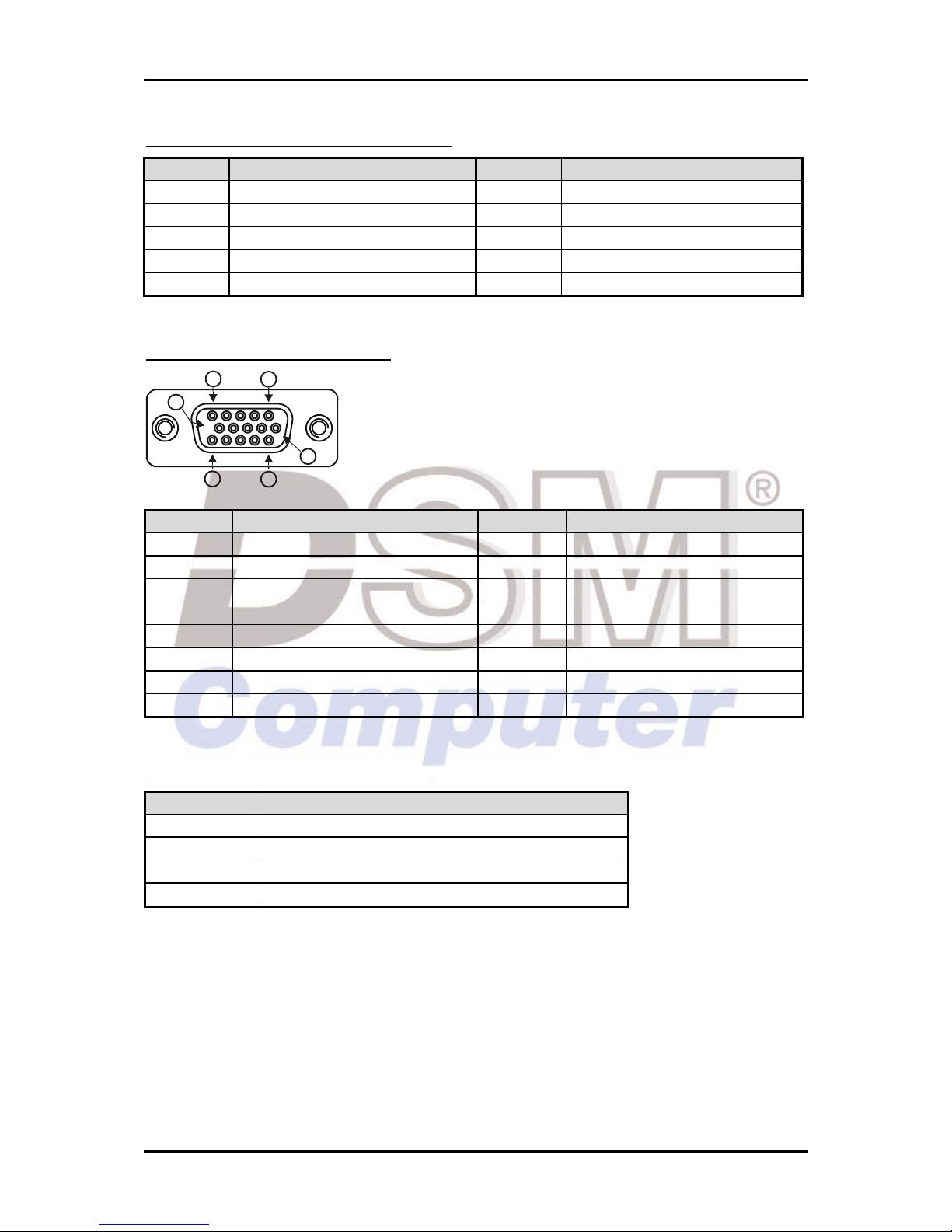
J33/J34 : Serial Port-1/Port-2 Connector
PIN No. Signal Description PIN No.
Signal Description
1 Data Carrier Detect (DCD) 2 Data Set Ready (DSR)
3 Receive Data (RXD) 4 Request to Send (RTS)
5 Transmit Data (TXD) 6 Clear to Send (CTS)
7 Data Terminal Ready (DTR) 8 Ring Indicator (RI)
9 GND 10 NC
J35 : D-SUB15 VGA Connector
1
11
15
5
10
6
PIN No. Signal Description PIN No.
Signal Description
1 RED 2 GREEN
3 BLUE 4 ID0
5 Ground 6 Ground
7 Ground 8 Ground
9 NC 10 Ground
11 ID1 12 DDCDATA
13 HSYNC 14 VSYNC
15 DDCCLK
J36 : ATX Standby Power Connector
PIN No. Signal Description
4 ATX Power OK
3 ATX_5VSB
2 PS ON
1 GND

System Installation
96M4281o User’s Manual 3-1
Chapter 3
System Installation
This chapter provides you with instructions to set up your system. The additional
information is enclosed to help you set up onboard PCI device and handle WDT
operation in software programming.
3.1 Yonah/Merom Processor
Configuring System Bus
BLUEBOARD will automatically detect the CPU used. Support Package μFCPGA479
LV Yonah Dual Core processor CPU.
Installing mPGA 479MT Socket
1) Lift the handling lever of CPU socket outwards and upwards to the other end.

System Installation
96M4281o User’s Manual 3-2
2) Align the processor pins with pinholes on the socket. Make sure that the notched
corner or dot mark (pin 1) of the CPU corresponds to the socket’s bevel end. Then
press the CPU gently until it fits into place. If this operation is not easy or
smooth, don’t do it forcibly. You need to check and rebuild the CPU pin
uniformly.
3) Push down the lever to lock processor chip into the socket once CPU fits.
To un-install the current processor, use a screwdriver to disengage (open) the socket
actuator, as shown in Figure 1 below. The socket actuator should open after only a
half turn or so, and you should then be able to remove the processor with your
fingers.
 Loading...