

DSM Computer AG 96M4011o User Manual

96M4011o
Single Board Computer
User's Manual
P/N: B8980850 Version 1.4
Copyright © DSM Computer AG, 2004. All rights reserved.
All other brand names are registered trademarks of their respective owners.

Preface
Table of Contents
How to Use This Manual
Chapter 1 System Overview.......................................................................................................1-1
1.1 Introduction.................................................................................................................................. 1-1
1.2 Check List ..................................................................................................................................... 1-2
1.3 Product Specification ..................................................................................................................1-2
1.3.1 Mechanical Drawing......................................................................................................... 1-6
1.4 System Architecture .................................................................................................................... 1-6
Chapter 2 Hardware Configuration ...........................................................................................2-1
2.1 Jumper Setting ............................................................................................................................. 2-1
2.2 Connector Allocation .................................................................................................................. 2-2
Chapter 3 System Installation....................................................................................................3-1
3.1 Pentium 4 Processor.................................................................................................................... 3-1
3.2 Main Memory .............................................................................................................................. 3-2
3.3 M-systems Flash Disk ................................................................................................................. 3-2
3.4 Installing the Single Board Computer ...................................................................................... 3-3
3.4.1 Chipset Component Driver.............................................................................................. 3-3
3.4.2 Intel Integrated Graphics GMCH Chip.......................................................................... 3-3
3.4.3 On-board Fast Ethernet Controller ................................................................................. 3-4
3.4.4 On-board AC-97 Audio Device....................................................................................... 3-4
3.4.5 On-board 68-pin PCI connector....................................................................................... 3-4
3.5 Clear CMOS Operation............................................................................................................... 3-5
3.6 WDT Function.............................................................................................................................. 3-5
3.7 On-Board USB 2.0 Controller..................................................................................................... 3-6
3.8 Panel Display Output (Factory Optional only) ....................................................................... 3-7
3.9 GPIO.............................................................................................................................................. 3-7
Chapter 4 BIOS Setup Information............................................................................................4-1
4.1 Entering Setup.............................................................................................................................. 4-1
4.2 Main Menu ................................................................................................................................... 4-2
4.3 Standard CMOS Setup Menu ....................................................................................................4-3
4.4 IDE Adaptors Setup Menu......................................................................................................... 4-5
4.5 Advanced BIOS Feature ............................................................................................................. 4-6
4.6 Advanced Chipset Feature......................................................................................................... 4-9
4.7 Integrated Peripherals .............................................................................................................. 4-12
4.8 Power Management Setup ....................................................................................................... 4-17
4.9 PnP/PCI Configurations .......................................................................................................... 4-21
4.10 PC Health Status...................................................................................................................... 4-24
4.11 Frequency/Voltage Control................................................................................................... 4-25
4.12 Default Menu ...........................................................................................................................4-25
4.13 Supervisor/User Password Setting ...................................................................................... 4-26
4.14 Exiting Selection ...................................................................................................................... 4-27
Chapter 5 Troubleshooting........................................................................................................5-1
5.1 Backplane Setup........................................................................................................................... 5-1
5.2 Onboard Hardware Installation ................................................................................................ 5-4
5.3 BIOS Setting.................................................................................................................................. 5-6
5.4 OS Diagnostics ............................................................................................................................. 5-7

Preface
How to Use This Manual
The manual describes how to configure your 96M4011o system to meet
various operating requirements. It is divided into five chapters, with each chapter
addressing a basic concept and operation of Single Board Computer.
Chapter 1: System Overview. This chapter presents what you have in the inside of
box and give you an overview of the product specifications and basic system
architecture for this model of single board computer.
Chapter 2: Hardware Configuration Setting. This chapter shows the definitions and
locations of Jumpers and Connectors that you can easily configure your system.
Chapter 3: System Installation. This chapter describes how to properly mount the
CPU and main memory, M-system Flash disk, or optional flat panel display interface
module if any to get a safe installation and give you a programming guide of Watch
Dog Timer function. Besides, it will introduce and show you the driver installation
procedure about Graphics Controller.
Chapter 4: BIOS Setup Information. This chapter specifies the meaning of each
setup parameters and how to get advanced BIOS performance and update new
BIOS. In addition, POST checkpoint list will give you a guide of trouble-shooting.
Chapter 5: Troubleshooting. This chapter provides you a few useful tips to quickly
get your 96M4011o running with no failure. As basic hardware installation has
been addressed in Chapter 3, this chapter will basically focus on system integration
issues, in terms of backplane setup, BIOS setting, and OS diagnostics.
The content of this manual and EC declaration document is subject to change
without prior notice. These changes will be incorporated in new editions of the
document. DSM may make supplement or change in the products described in
this document at any time.
Updates to this manual, technical clarification, and answers to frequently asked
questions will be shown on the following web site: http://www.DSM.AG.

Preface
Remove Processor
Caution: Do not pull out processor without opening socket handle!
High viscosity thermal grease between processor and cooler will lead the processor be
pulled out from socket when taking cooler off.
This action may damage processor socket, which will cause poor contact between CPU
& socket.
Handling SBC
Caution: Do not just hold any single side of the SBC; hold evenly on both sides!
Heavy processor cooler shall bend the SBC when SBC being held just on one side.
The bending may cause serious soldering or circuit damage.
WARNING

System Overview
96M4011o User’s Manual 1-1
Chapter 1
System Overview
1.1 Introduction
96M4011o is a cost effective and high integration Pentium 4 applied
computing platform. It provides innovative, high integration, high quality Single
Board Computers in the applied computing market. The board is based on Intel
845GV chipset and support Intel latest high performance processor, Intel Socket 478
Pentium® 4 Processor, running at up to 3.06Ghz with 533Mhz Process system bus
that built on Intel ® 0.13 micron processor technology.
With Intel 845GV chipset that support high speed non-ECC DDR SDRAM, highperformance graphic controller AGP 4X controller and Intel fast Ethernet connection
enable 96M4011o to provide most versatile SBC in the market.
96M4011o was designed to meet all kind of applied computing application.
With Intel most advance mainstream chipset 845GV 96M4011o is aiming the
most wide range of Multimedia and networking application in the market.
Its proprietary PCI extension connector provides an easy way to add additional
functions like U160 SCSI or 2nd LAN device in minutes.
It’s compact design with industry PICMG standard form factor make it the best
solution for high density server. High reliability and easy-to-maintain nature (lower
MTTR) meet high-availability need of Mission critical application.

System Overview
96M4011o User’s Manual 1-2
1.2 Check List
The 96M4011o package should cover the following basic items:
One 96M4011o single board computer
One serial port kit with two COM ports
One Parallel port cable kit
One FDC cable
One IDE cable
One Y-cable cable for PS/2 keyboard and mouse
One 4-pin ATX power control cable for backplane connection
One Installation Resources CD-Title
CPU holder
One booklet of 96M4011o manual
One Multimedia kit with MIC, Line In, Line Out and Single-port USB connectors
(Optional Accessory, not included in standard package)
If any of these items is damaged or missing, please contact your vendor and keep all
packing materials for future replacement and maintenance.
1.3 Product Specification
Main Features
Intel 845GV based PICMG SBC with VGA/LAN/Audio and optional SCSI 160 or
2nd LAN module through proprietary connector (PCI bus)
Support mPGA478 socket Pentium 4
PSB speed 400/533 MHz
Support DDR200/266 DDR SDRAM memory up to 2GB without ECC support
Intel GMCH integrated graphic device with up to 64MB Dynamic display
memory
ICH4 integrated fast Ethernet controller
Support two a DMA/33/66/100 IDE
Support Standard I/O including 2 serial ports, 1parallel port, one IrDA port, 3
USB ports (USB 2.0 compliant) and 8 high driving GPIO.
Compliant with PCI Bus spec V2.1
Full-size All-in-one SBC with PICMG 1.0 Rev 2.0 compliant
Proprietary socket for optional daughter board (PCI bus) for SCSI or 2nd LAN
options

System Overview
96M4011o User’s Manual 1-3
System Specifications
Chipset
- Intel 845GV
- Intel GMCH and Intel ICH4
CPU
- Support one mPGA478 socket Pentium 4 Processor up to 3.06GHz
- PSB speed 400/533 MHz
- With standard CPU retention for easy heat sink and fan installation
- 512KB or 256KB L2 Cache Memory Intel® Pentium® 4 or Celeron Processor
Main memory
- Two 184-pin DIMM sockets
- Supports 200/266Mhz DDR SDRAM up to 2GB
- Available bandwidth up to 2.1GB/s (DDR266)
- 64/128/256/512 MB SDRAM technologies
- 2.5V DDR SDRAM support
- Registered DIMM not supported
- Do not support ECC functionality
System BIOS
- Phoenix - Award BIOS with PC’98 support
- 4Mbit flash ROM (Intel FWH) for easy upgrade
- Support DMI, PnP, Green function and ACPI
- ACPI support suspend to RAM, USB wake up.
On Board I/O
- PCI IDE Interface
Support two enhanced IDE channel up to four HDDs with PIO mode 4, Ultra
DMA/33/66/100 model transfer and Bus master feature.
- Floppy Drive Interface
Support one FDD port up to two floppy drives and 5-1/4"(360K, 1.2MB), 3-1/2"
(720K, 1.2MB, 1.44MB, 2.88MB) diskette format and 3-mode FDD
- Serial Ports
Support two high-speed 16C550 compatible UARTs with 16-byte T/R FIFOs
RS-232/422/485 selectable for COM2 by jumper
- IR Interface
Support one 6-pin header for serial Standard Infrared wireless communication
Shared with one serial port
- Parallel Port
Support one parallel port with SPP, EPP and ECP modes
- USB Interface
USB 2.0 compliant
Support three USB (Universal Serial Bus) ports for high-speed I/O peripheral
devices
One on bracket; two with pin header

System Overview
96M4011o User’s Manual 1-4
- PS/2 Mouse and Keyboard Interface
Support one 6-pin Mini-DIN connector for PS/2 mouse/keyboard connection
through Y-Cable separation and one 5-pin shrouded connector for PS/2
keyboard connection through backplane connection
Auxiliary I/O
- One 2-pin system reset switch
- One 4-pin external speaker interface
- One 5-pin key-lock header
- One 2-pin HDD active indicator interface
- One 8-pin USB dual port interface
- One 4-pin ATX power control interface
- One 10-pin connector for GPIO (4 GPI and 4 GPO)
Bracket
- Support one RJ45 connectors (LAN)
- One VGA connector
- One USB Port
- One PS/2 Keyboard/mouse connector (Mini din)
Hardware Monitoring
Support CPU voltage, temperature and FAN monitoring
Watchdog Timer
- Support WDT function through software programming
- Software programmable time-out internal setting
- Generate system reset or NMI
Solid State Disk (SSD)
- Reserved one 32-pin socket for M-systems Flash Disk (Disk-on-Chip,DOC) up
to 512MB
- DOS, Windows, Win95, NT (bootable) drivers and Utility supported
Real Time Clock/Calendar (RTC)
- Support Y2K Real Time Clock/Calendar with battery backup for 7-year data
retention
- A high quality external Li battery
ACPI compliant support the full-on (S0), Stop Grant (S1), Suspend to RAM (S3),
Suspend to Disk (S4), and soft-off (S5) power management states.
ATX Power Control Interface
One 4-pin header to support ATX power control with Modem Ring-On and
Wake-On-LAN function
Auxiliary I/O Interfaces
System reset switch, external speaker, Keyboard lock and HDD active LED, etc.
Power Good
On-Board power good generator with 200 ms to 300 ms reset duration
CPU Cooling Fan
Support one 3-pin header with wafer

System Overview
96M4011o User’s Manual 1-5
Additional Main Peripheral Function
On Board High performance Graphics (Intel GMCH Integrated Graphics
controller)
- IGD with analog display port
- Analog Display Support up to 2048 x 1536 @ 60Hz refresh
- AGP 2.0, AGP 4X. 1.5V
- Software DVD at 30 fps, full screen
- Motion Video Acceleration
One On Board Ethernet (one ICH4 Integrated MAC controller with external
10/100 Mb phy)
- Support 10/100 MB Base-TX
- One RJ-45 phone jack.
- Support two LEDs to indicator LAN access and link status on RJ45 jack
- Support Wake-on-LAN
PICMG Compliant PCI plus ISA bus Interface
- Follow PICMG 1.0 Rev 2.0 standard (32-bit PCI and 16-bit ISA)
- Fully complies with PCI Local Bus specification V2.1 (support 4 master PCI
slots)
On Board PCI to ISA Bridge
- Support ISA Bus mastering
- Support standard ISA slot
- 64mA high driving
- Support M-system DOC
ISA64 High ISA-Bus Driving Capability
Support 64mA high driving capability for ISA-Bus slots on back plane
On-board 68-pin PCI connector
Support one additional PCI daughter board
Optional daughter Board Ultra 160 SCSI (AIC 7892 chipset)
- Support one 68-pin SCSI interface
- SCSI data transfers up to 160MB/sec
Physical and Environmental requirements
- Outline Dimension (L x W) 338.5mm (13.33”) X 122mm (4.8”)
- Power Requirements:
. +12V (CPU) @4.0A
. +12V (System) @0.8A
. +5V @2.8A
- Test configuration:
. CPU: Intel P4 2.4GHz/533MHz FSB/512KB L2 Cache
. Memory: DDR SDRAM 512MBx2
. Primary Master IDE HDD: Samsung SV2042H (20GB)
. OS: Microsoft Windows 2000 + SP2
System Overview
96M4011o User’s Manual 1-6
. Test Programs: 3D Mark 2001 for loading VGA and Burning Test V2.2 for
loading CPU
. Connected Fans: Only CPU fan connected
. Run Time: 10 minutes
- Operating Temperature: 0°C ~ 55°C (32°F ~ 131°F)
- Storage Temperature: -20°C ~ 80°C
- Relative Humidity: 0% ~ 95%, non-condensing
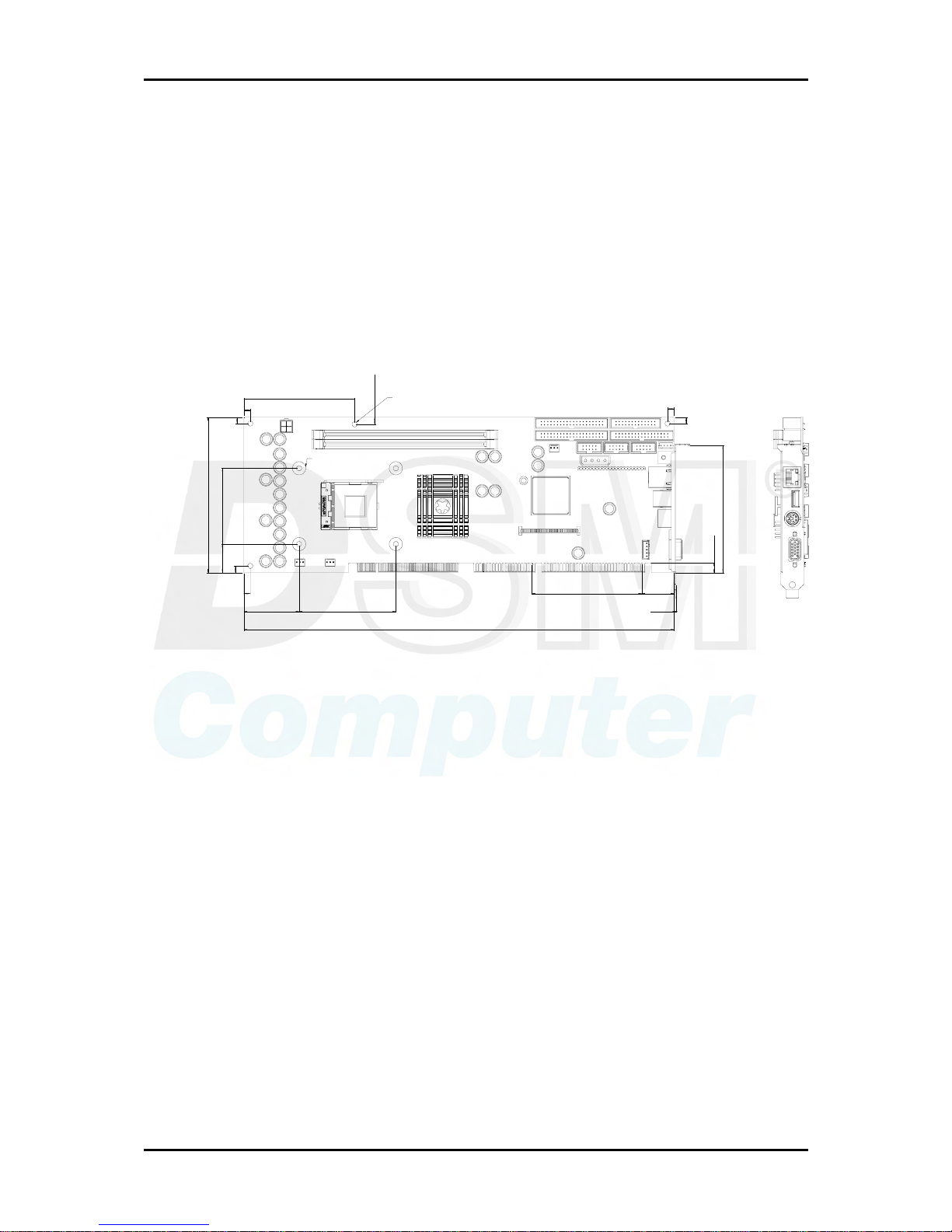
1.3.1 Mechanical Drawing
5
43.43 76.20
5.21
22.33
59.43
121.89
5
5
87.12
5.66
5
5
99.82
7.62
25.3986.35
1.50
338.58
4- Pad ?10.4
4- Holes ?4.0
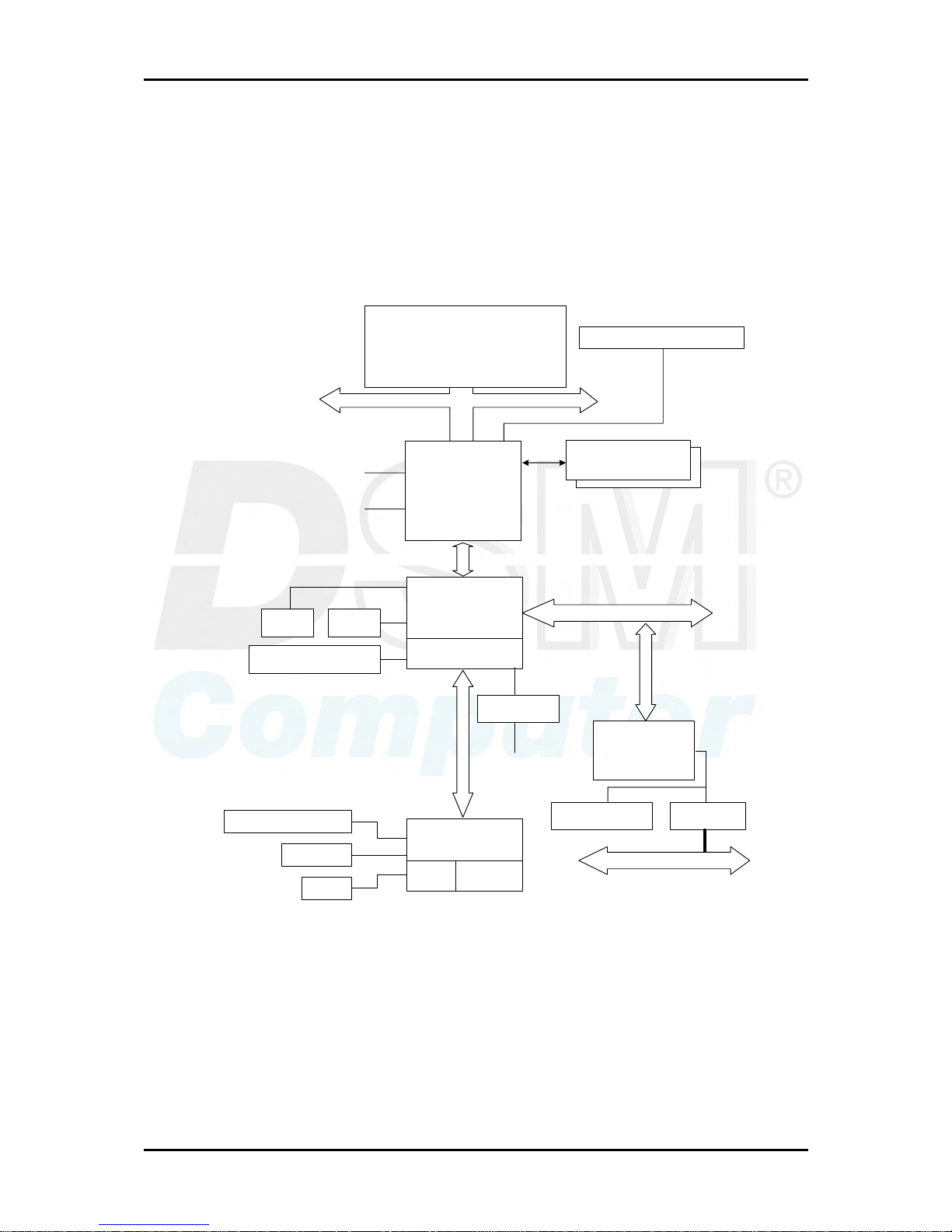
1.4 System Architecture
The system architecture of 96M4011o includes two main Intel chips, Intel
845GV chipset supports Pentium-4/Celeron processor, DDR-SDRAM, 2D/3D
graphic display, and its ICH4 supports PCI bus interface, APM, ACPI compliant
power management, USB port, SMBus communication, and Ultra DMA/33/66/100
IDE Master, and it also provides a Fast Ethernet controller. The W83627HF (I/O
Controller) is responsible for PS/2 Keyboard/Mouse, UARTs, FDC, Hardware
Monitor, Parallel, Watch Dog Timer and Infrared interface.
The special pin configuration of the CPU socket adopts the 478 pins in total. This
new generation CPU provides better performance to many applications.
The PCI-to-ISA bridge supports a standard 16-bit ISA bus interface which is applied
for all slower I/O operations. In 96M4011o, it supports DiskOnChip (DOC) for
M-systems Flash disk.
System Overview
96M4011o User’s Manual 1-7
There is one on-board PCI Fast Ethernet via RJ-45 Ports to support full functionality
of 96M4011o AIO SBC (All-In-One Single Board Computer).
The on-board 68-pin PCI connector supports one additional PCI daughter board for
further extension.
CLOCK GENERATOR
2 DDR MEMORY x 2 (up
to 2GB in t otal)
DDR 200/266
82845GV
GMCH
HOST BUS (400/533 MHz)
82801DA
ICH4
(420 EBGA)
Hub Link
PCI BUS
ITE IT8888
DiskOnChip BUFFER
ISA BUS
Golden Finger
SUPER I/O
W83627HF
MAC
WDT
Hardware
Monitor
System Block Diagram
IDE 2IDE 1
IDE Bus Master
2 ATA 100 IDE Channels
3 x USB 2.0 PORT S
LPC
2UART/LPT/FDD/IR
Mouse
Keyboard
2
1
Intel 82562
LAN
CRT
IntelR PentiumR 4
Processor/
Northwood Processor
DVO
(Optional)
Hardware Configuration
96M4011o User’s Manual 2-1
Chapter 2
Hardware Configuration
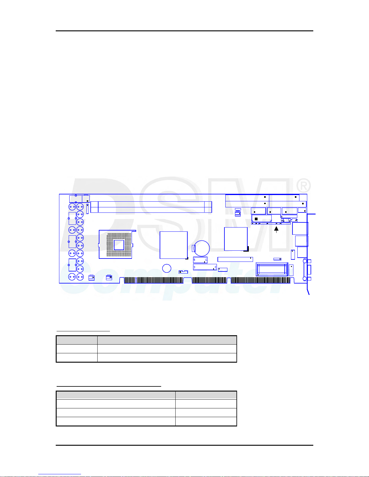
This chapter indicates jumpers’, headers’ and connectors’ locations. Users may find
useful information related to hardware settings in this chapter. The default settings
are indicated with a star sign (Ì).
2.1 Jumper Setting
For users to customize 96M4011o’s features. In the following sections, Short
means covering a jumper cap over jumper pins; Open or N/C (Not Connected)
means removing a jumper cap from jumper pins.
Users can refer to Figure 2-1 for the Jumper locations.
Figure 2-1 96M4011o Jumper/Connector Location
JP1: CMOS Clear
JP1 Function
1-2 Short Normal Operation Ì
2-3 Short Clear CMOS / Contents
JP2: COM2(J9) Interface Selection
J
P2
5-6,9-11,10-12,15-17,16-18 Short RS-232 Ì
3-4,7-9,8-10,13-15,14-16,21-22 Short RS-422
1-2,7-9,8-10,19-20 Short RS-485
J26
J38
J6
J7
MPGA478B
845
BZ
BAT
J34
J36
J35
J16
J23
ICH4
JP1
J5
J1
J2
J8
J31
J11
J3
J9
J25
J29
J24
J15
J13
J18
J19
U26
J20
JP2
J4 JP3 J37 J10
J32 J33 J28 J30 J27 J12
J14
DIMM1
DIMM2
Hardware Configuration
96M4011o User’s Manual 2-2
JP3: AT/ATX Power Selection
J
P3
1-3, 2-4 Short AT Power
3-5,4-6 Short ATX Power Ì
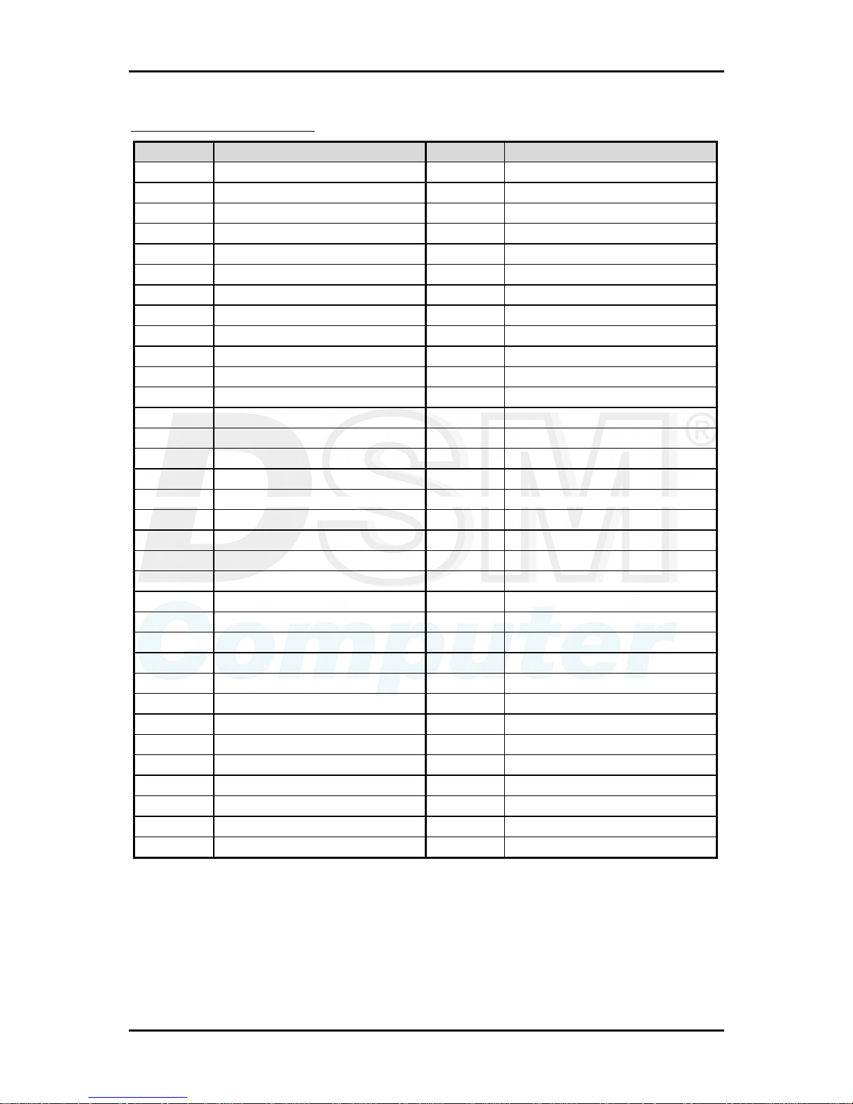
2.2 Connector Allocation
I/O peripheral devices and flash disk are connected to the interface connectors and
DOC socket on this single board computer (Figure 2-1)
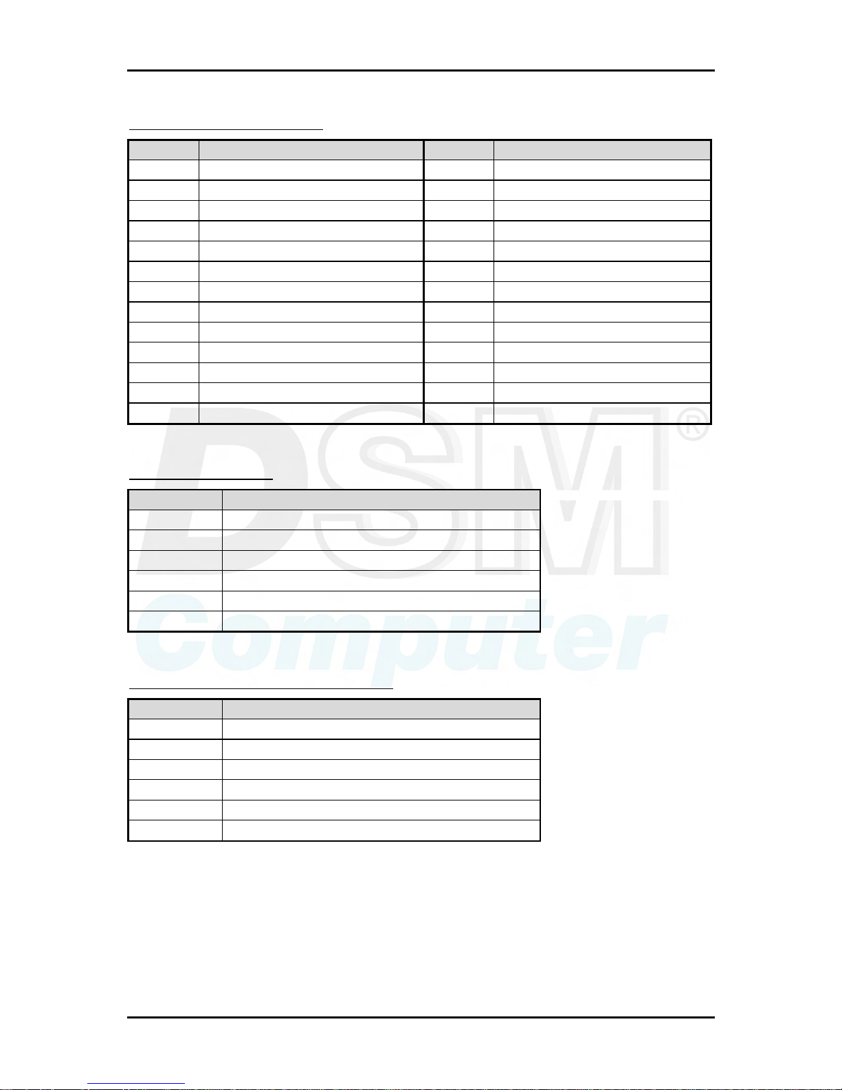
Connector’s Function List
J
1 Primary IDE Connector (IDE1)
J
2 Secondary IDE Connector (IDE2)
J
3 FDC Interface Connector
J
5 Power FAN Connector
J
6 CPU Fan Connector
J
7 System Fan Connector
J
8 COM1 Serial Port (RS-232)
J
9 COM2 Serial Port (RS-232/422/485)
J
10 External Wake On LAN Connector
J
11 Parallel Port Connector
J
12 IrDA Connector
J
13 PS/2 keyboard/Mouse Connector 6-pin Mini-DIN
J
14 External keyboard Connector Connect to Backplane
J
15 Single-port USB Connector
J
16 External USB Connector
J
18 Audio MIC/Line-in/Line-out
J
19 Audio CD-in Connector
J
20 On-board VGA CRT Connector
J
23 68-pin PCI Connector
J
24 Ethernet RJ-45 Connector
J
25 General Purpose I/O Connector
J
26 12V CPU Power Connector Must to connect
J
27 Hard Disk Drive LED Connector Connect to Chassis
J
28 External Speaker Connector Connect to Chassis
J
29 ATX Power Control Connector Connect to Backplane
J
30 Power LED and Keyboard Lock Connect to Chassis
J
31 Standalone Power Connector Only for standard one
J
32 ATX Power Button Interface Connect to Chassis
J
33 Reset Button Connector Connect to Chassis
J
34 DVO Power Connector Optional
J
35 DVO Connector -1 Optional
J
36 DVO Connector -2 Optional
J
38 Front SMBus Connector

Hardware Configuration
96M4011o User’s Manual 2-3
Pin Assignments of Connectors
J1/J2: Primary/Secondary IDE Connector (IDE1/IDE2)
PIN No. Signal Description PIN No. Signal Description
1 RESET# 2 Ground
3 Data 7 4 Data 8
5 Data 6 6 Data 9
7 Data 5 8 Data 10
9 Data 4 10 Data 11
11 Data 3 12 Data 12
13 Data 2 14 Data 13
15 Data 1 16 Data 14
17 Data 0 18 Data 15
19 Ground 20 N/C
21 DMA REQ 22 Ground
23 IOW# 24 Ground
25 IOR# 26 Ground
27 IOCHRDY 28 Pull-down
29 DMA ACK# 30 Ground
31 INT REQ 32 N/C
33 DA1 34 CBLID#
35 DA0 36 DA2
37 HDC CS0# 38 HDC CS1#
39 HDD Active# 40 Ground
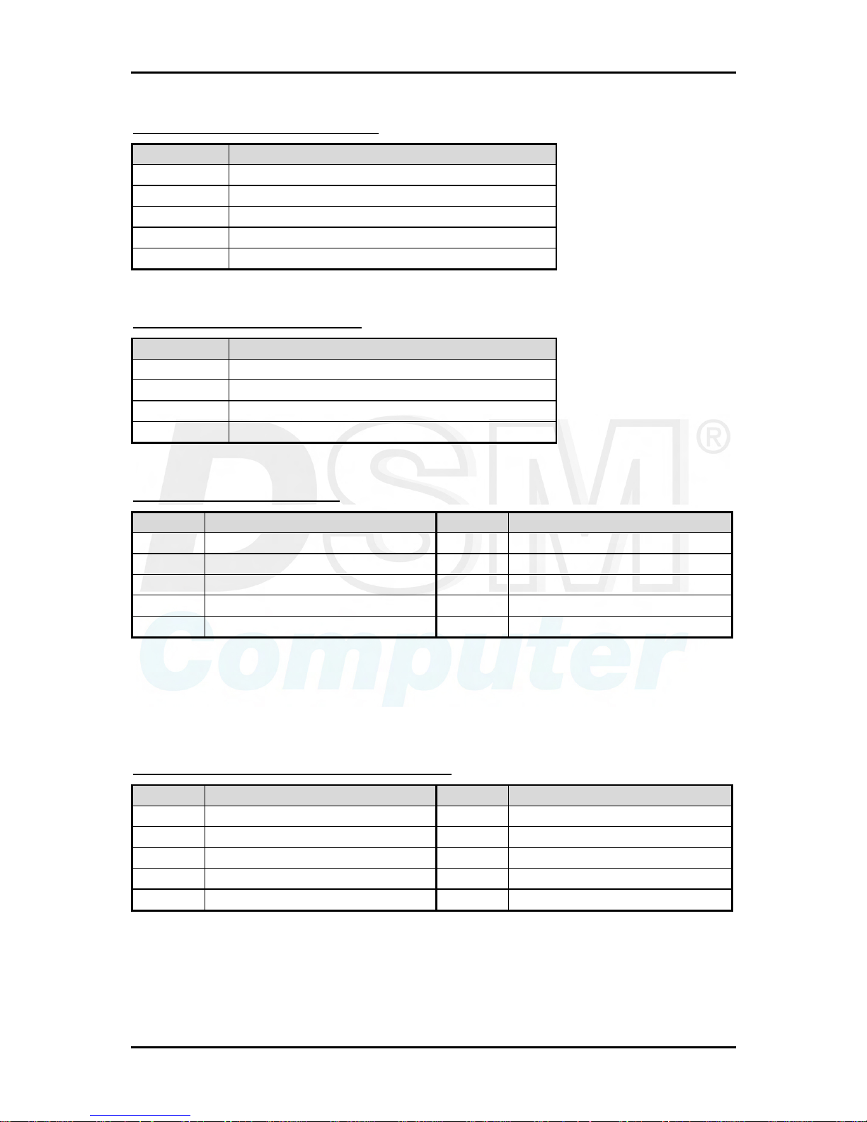
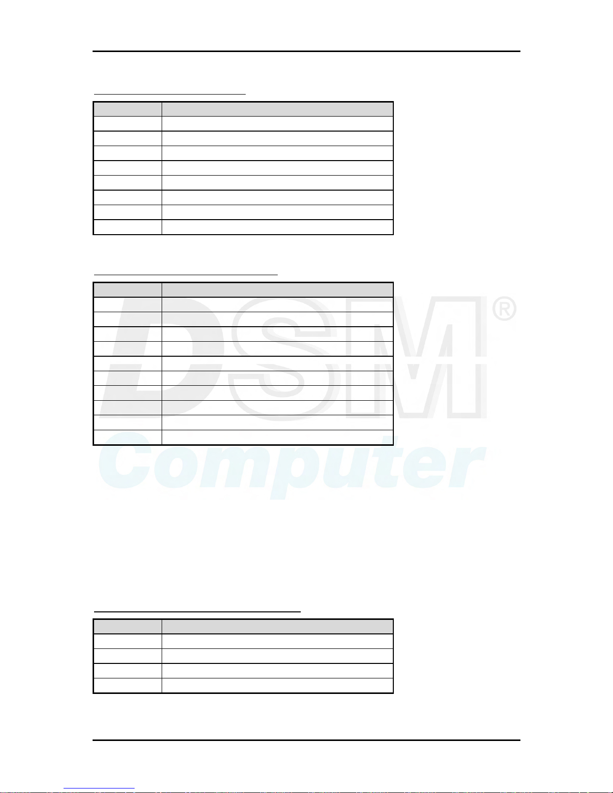
J3: FDC Interface Connector
PIN No. Signal Description PIN No. Signal Description
1 Ground 2 Density Select 0
3 Ground 4 N/C
5 Ground 6 Density Select 1
7 Ground 8 Index#
9 Ground 10 Motor ENA#
11 Ground 12 Drive Select B#
13 Ground 14 Drive Select A#
15 Ground 16 Motor ENB#
17 Ground 18 Direction#
19 Ground 20 Step#
21 Ground 22 Write Data#
23 Ground 24 Write Gate#
25 Ground 26 Track 0#
27 Ground 28 Write Protect#
Hardware Configuration
96M4011o User’s Manual 2-4
29 N/C 30 Read Data#
31 Ground 32 Head Select#
33 N/C 34 Disk Change#
J5/J6/J7 : Power/CPU/System Fan Connector
PIN No. Signal Description
1 Ground
2 +12V
3 Fan Speed Detecting signal
Note:
The fan must be a 12V fan. And there is not any over current protection.
J8/J9: COM1/COM2 Serial Port 1/2 Connector
PIN No. Signal Description
RS-232 RS-422 RS-485
1 DCD (Data Carrier Detect) TX- DATA2 RXD (Receive Data) TX+ DATA+
3 TXD (Transmit Data) RX+ N/C
4 DTR (Data Terminal
Ready)
RX- N/C
5 GND (Ground) GND GND
6 DSR (Data Set Ready) N/C N/C
7 RTS (Request to Send) N/C N/C
8 CTS (Clear to Send) N/C N/C
9 RI (Ring Indicator) N/C N/C
10 N/C N/C N/C
Notes:
1) J8 is fixed as RS-232
2) J9 is configurable as RS-232/422/485 with jumper JP2
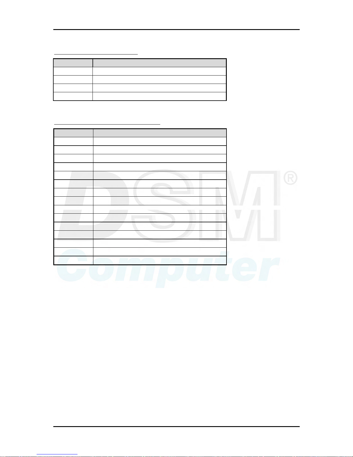
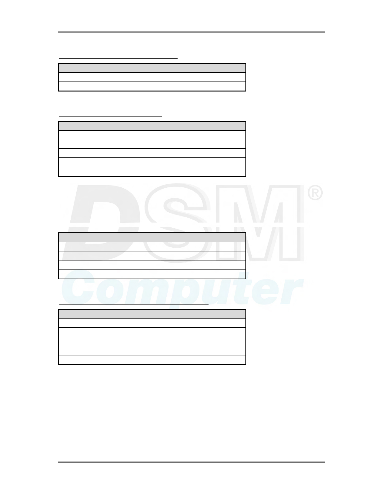
J10: External Wake On LAN Connector
PIN No. Signal Description
1 5VSB
2 Ground
3 External WOL Signal Input (Active low)
Hardware Configuration
96M4011o User’s Manual 2-5
J11: Parallel Port Connector
PIN No. Signal Description PIN No. Signal Description
1 Strobe# 14 Auto Form Feed#
2 Data 0 15 Error#
3 Data 1 16 Initialization#
4 Data 2 17 Printer Select IN#
5 Data 3 18 Ground
6 Data 4 19 Ground
7 Data 5 20 Ground
8 Data 6 21 Ground
9 Data 7 22 Ground
10 Acknowledge# 23 Ground
11 Busy 24 Ground
12 Paper Empty 25 Ground
13 Printer Select 26 N/C
J12: IrDA Connector
PIN No. Signal Description
1 +5V
2 N/C
3 IRRX
4 Ground
5 IRTX
6 N/C
J13: PS/2 Keyboard/Mouse Connector
PIN No. Signal Description
1 Mouse Data
2 Keyboard Data
3 Ground
4 5V Dual
5 Mouse Clock
6 Keyboard Clock
Hardware Configuration
96M4011o User’s Manual 2-6
J14: External Keyboard Connector
PIN No. Signal Description
1 Keyboard Clock
2 Keyboard Data
3 N/C
4 Ground
5 5V Dual
J15: Single-port USB Connector
PIN No. Signal Description
1 5V Dual
2 USB03 USB0+
4 Ground
J16: External USB Connector
PIN No. Signal Description PIN No. Signal Description
1 5V Dual 2 Frame Ground
3 USB2- 4 Ground
5 USB2+ 6 USB3+
7 Ground 8 USB3-
9 Frame Ground 10 5V Dual
Note:
5V Dual is always available. It’s supplied by either 5V VCC power source in normal
operation mode or 5V standby power source in standby mode.
J18: Audio MIC/Line-in/Line-out Connector
PIN No. Signal Description PIN No. Signal Description
1 MIC with Reference Voltage 2 Analog Ground
3 Line-in Left Channel 4 Analog Ground
5 Line-in Right Channel 6 Analog Ground
7 Line-out Left Channel 8 Analog Ground
9 Line-out Right Channel 10 N/C
Note:
The Reference Voltage on MIC signal offers 2.25V~2.75V with 5mA drive
Hardware Configuration
96M4011o User’s Manual 2-7
J19: Audio CD-in Connector
PIN No Signal Description
1 CD-in Left Channel
2 CD Ground
3 CD Ground
4 CD-in Right Channel
J20: On-board VGA CRT Connector
PIN No. Signal Description
1 Red
2 Green
3 Blue
4 Monitor ID0 (MONID0) (5V I/F)
5 Ground
6 Ground
7 Ground
8 Ground
9 N/C
10 Ground
11 Monitor ID1 (MONID1) (5V I/F)
12 VGA DDC Data (5V I/F)
13 Horizontal Sync. (HSYNC) (5V I/F)
14 Vertical Sync. (VSYNC) (5V I/F)
15 VGA DDC Clock (5V I/F)
Hardware Configuration
96M4011o User’s Manual 2-8
J23: 68-pin PCI Connector
PIN No. Signal Description PIN No. Signal Description
1 +5V 2 AD0
3 AD1 4 AD2
5 AD3 6 AD4
7 AD5 8 AD6
9 AD7 10 Ground
11 +5V 12 AD8
13 AD9 14 AD10
15 AD11 16 AD12
17 AD13 18 AD14
19 AD15 20 Ground
21 +5V 22 AD16
23 AD17 24 AD18
25 AD19 26 AD20
27 AD21 28 AD22
29 AD23 30 Ground
31 +5V 32 AD24
33 AD25 34 AD26
35 AD27 36 AD28
37 AD29 38 AD30
39 AD31 40 Ground
41 +5V 42 C/BE#0
43 C/BE#1 44 C/BE#2
45 C/BE#3 46 PAR
47 FRAME# 48 TRDY#
49 IRDY# 50 Ground
51 +5V 52 STOP#
53 DEVSEL# 54 PERR#
55 SERR# 56 REQ#4
57 GNT#4 58 REQ#5
59 GNT#5 60 Ground
61 PCI Clock1 62 PCI Clock2
63 PCIRST# 64 LOCK#
65 IRQ#A 66 IRQ#B
67 IRQ#C 68 IRQ#D
Hardware Configuration
96M4011o User’s Manual 2-9
J24: Ethernet RJ-45 Connector
PIN No. Signal Description
1 TD+
2 TD3 TDC
4 Termination to Ground
5 Termination to Ground
6 RDC
7 RD+
8 RD-
J25: General Purpose I/O Connector
PIN No. Signal Description
1 General Purpose I/O Port 1 (GPIO1)
2 General Purpose I/O Port 2 (GPIO2)
3 General Purpose I/O Port 3 (GPIO3)
4 General Purpose I/O Port 4 (GPIO4)
5 Ground
6 Buffered Digital Output Port 1 (DO1)
7 Buffered Digital Output Port 2 (DO2)
8 Buffered Digital Output Port 3 (DO3)
9 Buffered Digital Output Port 4 (DO4)
10 +5V
Notes:
1) All General Purpose I/O ports can only adapt standard TTL ± 5% signal level
(0V/5V). Pin 1~4 can be either input or output, while pin 6-10 can only be digital
output.
2) The 4 extra DO ports are provided for the applications that need higher driving
capability. Through invert amplitude respected to GPIO port, each open-drain DO
port can stand maximum fan out for up to 100mA, rather than 12mA direct driven
by GPIO port.
J26: 12V CPU Supplementary Connector
PIN No. Signal Description
1 Ground
2 Ground
3 +12V
4 +12V
Hardware Configuration
96M4011o User’s Manual 2-10
J27: Hard Disk Drive LED Connector
PIN No. Signal Description
1 +5V (390 ohm pull-up for HDD LED+)
2 HDD Active # (HDD LED-)
J28: External Speaker Connector
PIN No. Signal Description
1 Speaker Signal Output (Open-drain w/
internal series 33 Ohm)
2 N/C
3 Ground
4 +5V
Note:
The pull-high voltage of external speaker is limited at 5V maximum.
J29: ATX Power Control Connector
PIN No. Signal Description
1 ATX Power Good Signal (PW-OK)
2 ATX 5V Stand-by (5VSB)
3 ATX Power On Control (PS-ON)
4 Ground
J30: Power LED and Keyboard Lock Connector
PIN No. Signal Description
1 +5V (470 Ohm pull-up for power LED+)
2 N/C
3 Ground (For Power LED-)
4 Keyboard Lock Signal Input (Active low)
5 Ground
 Loading...