

DSM Computer AG 96D2431o, 96D2471o, 96D2461o, 96D2481o User Manual

User's Guide Revision. B3 April, 2001
DSM Computer AG
96D2431o
96D2461o
96D2471o
96D2481o
Single Board Computer
User′s Guide

User's Guide Revision. B3 April, 2001
DSM Computer AG
@Copyright 2000
All Rights Reserved
Manual edition B3, April 2001
The information in this document is subject to change without prior notice in order to improve reliability,
design and function and does not represent commitment on the part of the manufacturer.
In no event will the manufacturer be liable for direct, indirect, special, incidental, or consequential damages
arising out of the use or the possibility of such damages.
This document contains proprietary information protected by copyright. All rights are reserved. No part of
this manual may be reproduced by any mechanical, electronic, or other means in any form without prior
written permission of the manufacturer.
Trademarks
IBM PC is a registered trademark of International Business Machines Corporation. Intel and Pentium are
registered trademarks of Intel Corporation. Award is a registered trademark of Award Software, Inc. Other
product names mentioned herein are used for identification purposes only and may be trademarks and/or
registered trademarks of their respective companies.

User's Guide Revision. B3 April, 2001
DSM Computer AG
How to use this guide
This manual is written to help you use the CPU board. It describes how to arrange various settings on the
Pentium CPU board to meet your requirements. It is briefed as follows:
Chapter 1, “Introduction” gives an overview of the product‘s specifications. It also tells you what are
included in the product package.
Chapter 2, “Switches and Connectors” describes the definitions and positions of Jumpers and
Connectors that you may easily configure and set up per your requirement.
Chapter 3, “Capability Expanding” describes how to change or expand the CPU Board by changing the
system memory and CPU to get more power out from the CPU board.
Chapter 4, “Award BIOS Setup” describes how to use the advanced PCI/Green BIOS to control almost
every feature of the CPU board.
The Appendix A describes how to set up the Watch Dog Timer (WDT) and gives an example to program the
WDT.

User's Guide Revision. B3 April, 2001
Content
Contents
CHAPTER 1 INTRODUCTION........................................................................................ 1-3
1-1 SPECIFICATIONS ................................................................................................................................1-2
CHAPTER 2 SWITCHES AND CONNECTORS.............................................................. 2-1
2-1 MAIN BOARD LAYOUT.........................................................................................................................2-1
2-2 SWITCHES .........................................................................................................................................2-2
2-3 CONNECTORS ....................................................................................................................................2-3
CHAPTER 3 CAPABILITY EXPANDING......................................................................... 3-6
3-1 SYSTEM MEMORY ..............................................................................................................................3-6
3-2 CHANGE CPU....................................................................................................................................3-7
CHAPTER 4 AWARD BIOS SETUP................................................................................ 4-1
4-1 BIOS SETUP .....................................................................................................................................4-1
Entering Setup ........................................................................................................................................4-1
Control Keys ...........................................................................................................................................4-2
Getting Help ............................................................................................................................................4-3
The Main Menu .......................................................................................................................................4-4
Standard CMOS Features ......................................................................................................................4-6
Advanced BIOS Features Setup Menu .................................................................................................. 4-9
Advanced Chipset Features Setup Menu............................................................................................. 4-13
Integrated Peripherals .......................................................................................................................... 4-17
Power Management Setup ...................................................................................................................4-21
PnP/PCI Configuration.......................................................................................................................... 4-25
PC Health Status ..................................................................................................................................4-27
Frequency/Voltage Control ................................................................................................................... 4-28
Supervisor/User Password Setting .......................................................................................................4-29
Power-On Boot .....................................................................................................................................4-30
4-2 BIOS REFERENCE - POST MESSAGE...............................................................................................4-31
POST Beep........................................................................................................................................... 4-31
Error Messages.....................................................................................................................................4-31
4-3 BIOS REFERENCE - POST CODES ...................................................................................................4-35
APPENDIX .....................................................................................................................43
APPENDIX A WATCH DOG TIMER .............................................................................................................. 43
Watch Dog Timer Working Procedure..................................................................................................... 43
Watch Dog Timer character and function ................................................................................................ 43

User's Guide Revision. B3 April, 2001
Content
Watch Dog Timer Control Register.......................................................................................................... 44
Watch Dog Timer Programming Procedure ............................................................................................ 45
Appendix B DVI Interface Pin Assignment……..……………………………………………………………..48
Appendix C Connectors Pin Assignment ……………...…………..…………………………………………49

User's Guide Revision. B3 April, 2001
Content
Chapter 1 Introduction
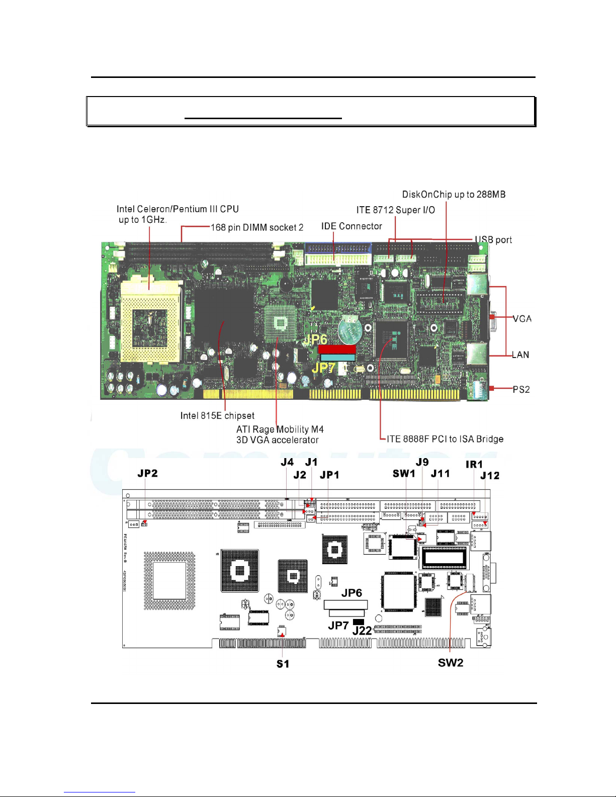
Welcome to the most powerful Intel 815E based single board computer.
The CPU board combines the high performance and exceptional value of Intel Celeron / Pentium III CPU
and 815E chipset with a full-featured, new generation, full-size single board computer. The Intel 815E
chipset, which combining internal graphics, LAN, and support for 4 USB ports, Ultra DMA66/100 IDE
interface, that meets the performance, stability and reliability requirements. Moreover, In order to meet the
network requirement, the CPU boards add one more Ethernet Controller Intel 82559 to support dual channel
Ethernet.
For the Display solution, not only the Intel 82815 (GMCH) chipset integrated Graphics controller, the CPU
board also provide On Board Optional ATI Rage Mobility M4 3D VGA accelerator with on die 8MB or 16MB
memory to support 4X AGP, which is compatible with DVI specification to support LCD panel.
The Intel 82815 (GMCH) chipset integrated Graphics with Intel Dynamic Video Memory Technology, the
D.V.M.T. employs direct AGP and intelligent arbitration to dynamically allocate and de-allocate memory for
textures for applications requiring additional texture memory. The operating system requires allocation of up
to 1MB of system memory to support legacy VGA. System properties will display up to 1MB less than
physical system memory available to the operating system. The graphics driver for the Intel 815
configuration will request up to 4MB of memory from the OS to implement a maximum 1024x768 screen
resolution, 2MB for a command buffer and 4MB used for Z-buffering. For high-end 3D applications, the
drivers request allocation of system memory from the O/S for AGP graphics textures. When the 3D
application is closed, the O/S will re-allocate system memory back for generic use.
The board is suitable and valuable for all the embedded applications, which also well support with the
Windows 2000, Windows NT and Linux Operation system.

User's Guide Revision. B3 April, 2001
Capability Expand
1-2
1-1 Specifications
z System Architecture
z Full size SBC with PCI/ISA Golden finger
z Intel Socket 370 Celeron/Pentium III with 66/100/133MHz FSB
z PCI V2.1 complied
z PICMG 1.0 (Rev.2.0) complied
z CPU Support
z Intel Brand New Socket 370 FC-PGA Celeron / Pentium III /New Pentium(0.13μ process)CPU with
128/256K cache on die, running at 66/100/133MHz FSB up to 1.26 GHz or above.
z Support streaming SIMD instruction
z Main Memory
z Support SDRAM up to 512MB (Max.), Non-ECC and Un-buffered Mode SDRAM
z 168 pin DIMM socket ×2
z Support 100/133MHz SDRAM interface
z Intel DVMT (Dynamic Video Memory Technology) offers a more efficient way to manage
system memory, enabling software drivers, working in concert with the intelligent arbiter
and the operating system, utilize all of the system memory to support richer graphics
applications.
z BIOS
z Award System BIOS
z Plug & Play support
z Advanced Power Management support
z Advanced Configuration & Power Interface support
z Jumperless for CPU FSB
z 2M bits flash ROM, upgradeable to 4M bits
z Chip Set
z Intel 815E chipsets
82815 × 1 Graphics and Memory Controller Hub (GMCH)
82801 × 1 I/O Controller Hub (ICH2)
82802 × 1 Firmware Hub (FWH)
z ITE 8888F × 1 PCI to ISA Bridge
z On Board VGA
z Intel 82815 (GMCH) chipset integrated with Graphics controller
z Hardware motion compensation assist for software MPEG/DVD decode
z 15 pin CRT connector ×1

User's Guide Revision. B3 April, 2001
Capability Expand
1-3
z On Board optional VGA
z ATI Rage Mobility M4 3D VGA accelerator. 4X AGP
z Fully PC 98 and PC 99 Compliant.
z Integrated 8MB of SDR Memory, upgradeable to 16MB
z 15 pin CRT connector ×1, DVI interface connector ×1
z On Board LAN
z Dual channel Ethernet support
z Intel 82801 (ICH2) chipset integrated LAN controller
z Intel 82559 Single Ethernet controller
z Alert-on-LAN by Intel 82801 ( ICH2)
z 10 Base T/100 Base TX support, full duplex
z Complied with PCI V2.1, IEEE802.3, IEEE 802.3U
z Drivers support:DOS/Windows, Windows 95/98/2000, Windows NT4.0, Netware, SCO Open Server
5.0, Linux.
z RJ45 connector ×2
z On Board proprietary PCI interface
z Reserved 32bit PCI interface for modules
z On Board I/O
z ITE 8712 Enhanced Super I/O on board
z SIO×2, with 2x16C550 UARTs, 10 pin header ×2, Optional RS422/485 ×1 for COM2
z PIO×1, bi-directional, EPP/ECP support, 26 pin connector ×1
z Floppy Disk controller:5.25” 360KB/1.2MB, 3.5” 720KB/1.2MB/1.44MB/2.88MB support, 34 pin
connector ×1
z On chip enhanced IDE x 2, PIO up to mode 4, DMA master up to mode 2, Ultra DMA/66/100 support,
40 pin connector × 2, total 4 E.IDE devices support
z On chip Keyboard, mouse controller, 5 pin connector x 1(for other keyboard); 6 pin mini DIN
connector ×1, for PS/2 keyboard/mouse
z On board USB port ×4 (6pin header ×2)
z On Board buzzer ×1
z On board 2 pin header for I
2
C
z On board 5 pin header for IrDA
z On Board 2 pin header for reset SW, 4 pin for speaker, 5 pin for keylock, 2 pin power SW
z ACPI Function
z Soft Power off
z Wake On LAN
z Wake On Keyboard

User's Guide Revision. B3 April, 2001
Capability Expand
1-4
z Wake On Ring
z RTC alarm wake up
z On Board Solid State Disk Socket
z On board reserved socket for DOC of M-systems:2MB~288MB, etc
z Power header beside IDE connector to support DOM
z System Monitor
z Derived from Super IO ITE 8712 to support system monitor.
z 7 voltage (For +3.3V, +5V, -5V , 5V STBY, +12V, −12V, and Vcore ×1)
z One Fan speed (For CPU)
z Two temperature
z Drivers support:Windows 95/98, Windows NT4.0/2000
z ISAMAX Support
z Maximize ISA signals to support ISA cards up to 20
z Watchdog Timer
z 1,2,4…64 seconds time-out intervals
z Dimensions
z 338.58mm(L) × 122mm(W)
z Power Requirements: ( For CPU Board Only, without peripherals )
Typical Maximum
+5V 10A 15A
-5V 0.5A 1A
+12V 0.5A 1A
-12V 0.5A 1A
+5Vsb 1.2A 1.5A
z Environments
z Operating temperatures:0°C to 60°C
z Storage temperatures:-20°C to 80°C
z Relative humidity:10% to 90% (Non-condensing)
z Certification
z CE
z FCC Class A

User's Guide Revision. B3 April, 2001
Capability Expand
1-5
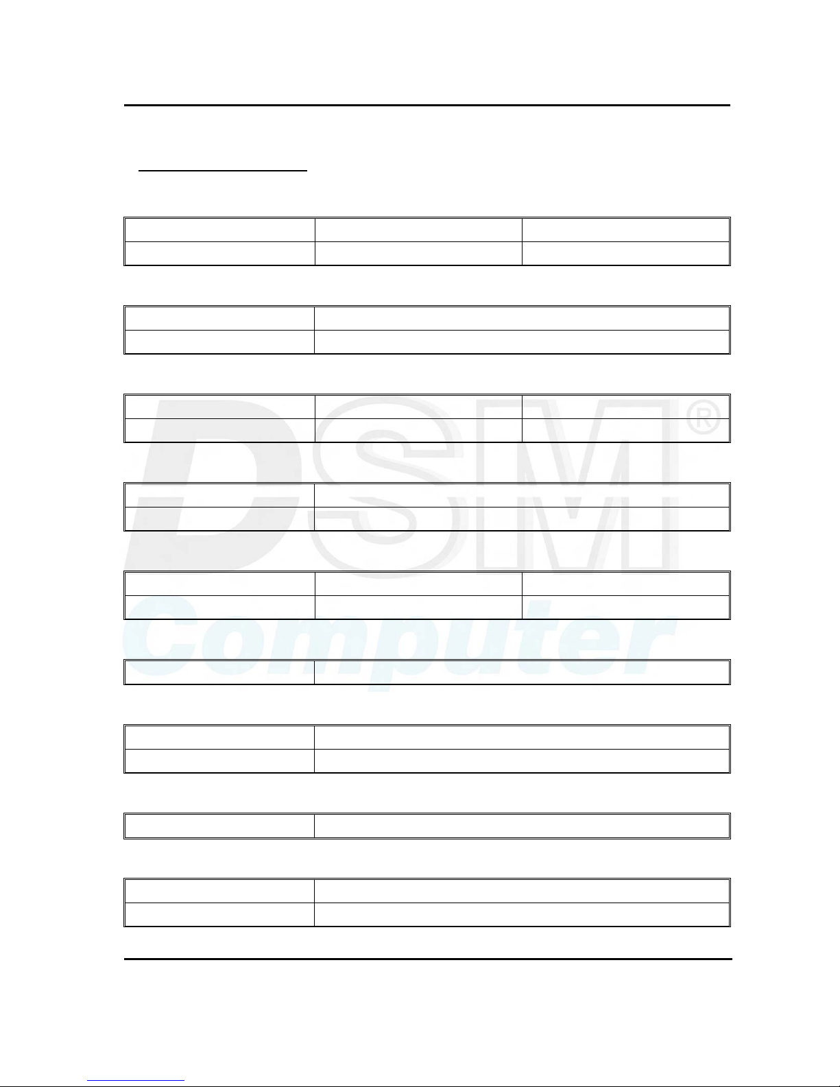
z Model Available
Model Name Description
96D2431o
Full-size Socket 370 Celeron/Pentium III FSB133MHZ CPU card w/VGA/LAN/
without PCI-PCI Bridge
96D2461o
Full-size Socket 370 Celeron/Pentium III FSB133MHZ CPU card w/VGA/Dual LAN/
without PCI-PCI Bridge
96D2471o
Full-size Socket 370 Celeron/Pentium III FSB133MHZ CPU card w/VGA/Dual LAN
96D2481o
Full-size Socket 370 Celeron/Pentium III FSB133MHZ CPU card w/ATI M4 VGA
w16MB /LAN
User's Guide Revision. B3 April, 2001
Capability Expand
2-1
Chapter 2 Switches and Connectors
2-1 Main Board Layout
This chapter gives the definitions and shows where to locate the positions of switches and connectors.

User's Guide Revision. B3 April, 2001
Capability Expand
2-2
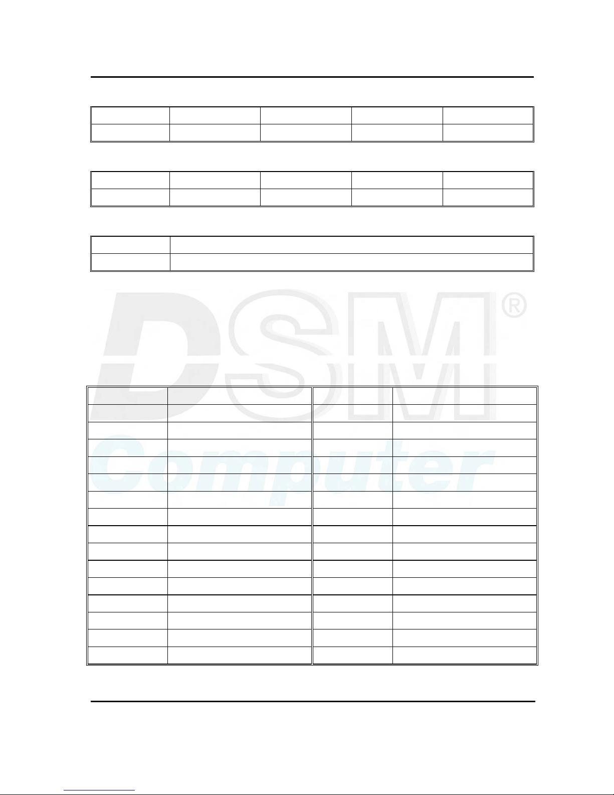
2-2 Switches
Switches on the CPU board are used to select options for different functions used. The switch-on or off is
to accommodate the variations of the following table.
Switch Setting Table (*: default setup)
S1 (*: Default setting)
1 2 3 4 CPU FSB / Memory
ON ON OFF OFF * Auto detect
OFF OFF ON ON 66MHZ / PC100 SDRAM
OFF OFF OFF ON 100MHZ / PC100 SDRAM
OFF OFF ON OFF 133MHZ / PC133 SDRAM
OFF OFF OFF OFF Reserve
SW2 (*: Default setting)
SW2 1 2 3 4 5 6 7 8 9 10
RS232 (*)
OFF OFF OFF ON OFF ON OFF OFF OFF OFF
RS422
ON ON ON OFF ON OFF ON ON ON ON
RS485
ON ON OFF ON ON OFF OFF OFF OFF ON
SW1 (*: Default setting)
SW1/M-System Disable (*) C0000 C8000 D0000 D8000
1 OFF ON ON ON ON
2 X ON ON OFF OFF
3 X ON OFF ON OFF
4 X X X X X
LVDS Power Selection (optional) (*: Default setting)
J22
*3V 1-2
5V 2-3
ATI Output selection (optional) (*: Default setting)
S2 - 1 S2 - 2 S2 - 3 S2 - 3
*CRT/DVI OFF OFF OFF X
LVDS ON ON ON X
User's Guide Revision. B3 April, 2001
Capability Expand
2-3
2-3 Connectors
Jumper/Connector Define
J1: External speaker connector
Pin 1 Pin 2, 3 Pin4
Speaker signal GND VCC5
J2: Power supply type select:
Pin1-2 short AT power
Pin2-3 short ATX power
J4: 5VSB power cable connector
Pin 1 Pin 2 Pin3
5VSB GND ATX power supply “PS_ON”
JP1: VCC5 power connector (for DOM)
Pin 1 Pin 2
VCC5 GND
JP3: Keylock connector
Pin 1 Pin 3,5 Pin 4
VCC5 GND keylock signal
J13: Reset button
Pin 1-2 Reset
JP4: CMOS set up
Pin 1-2 Pin 2-3
Normal Clear CMOS
J9: Power On button (ATX)
Pin 1-2 Power on
J11: IDE LED connector
Pin 1 Pin 2
VCC5 IDE LED signal
User's Guide Revision. B3 April, 2001
Capability Expand
2-4
IR1: IR connector
Pin 1 Pin 2 Pin 3 Pin 4 Pin 5
VCC5 NC IR_RX GND IR_TX
J12: External keyboard connector
Pin 1 Pin 2 Pin 3 Pin 4 Pin 5
Keyboard CLK Keyboard DAT NC GND5 VCC5
JP2: I2C connector
Pin 1 Pin2
SMB DAT SMB CLK
J17: Reserved
• JP6: DVI Connector
PIN No. Description PIN No. Description
1 TX2- 2 TX2+
3 Ground 4 TX1-
5 TX1+ 6 Ground
7 VCC5 8 Ground
9 Detect 10 TX0-
11 TX0+ 12 Ground
13 TXCLK+ 14 TXCLK-
15 Ground 16 Ground
17 DDC Clock 18 DDC Data
19 Reserved 20 Reserved
21 Reserved 22 Reserved
23 Reserved 24 Reserved
25 Reserved 26 Reserved
27 Reserved 28 Reserved
29 Reserved 30 Reserved
User's Guide Revision. B3 April, 2001
Capability Expand
2-5
• JP7: LVDS Connector
PIN No. Description PIN No. Description
1 Detect 2 TXL0-
3 TXL0+ 4 Ground
5 TXL1- 6 TXL1+
7 Ground 8 TXL2-
9 TXL2+ 10 Ground
11 TXL3- 12 TXL3+
13 Ground 14 TCLKL-
15 TCLKL+ 16 Ground
17 TXU0- 18 TXU0+
19 Ground 20 TXU1-
21 TXU1+ 22 Ground
23 TXU2- 24 TXU2+
25 Ground 26 TXU3-
27 TXU3+ 28 Ground
29 TCLKU- 30 TCLKU+
31 Ground 32 LVDS Power
33 Ground 34 Ground
User's Guide Revision. B3 April, 2001
Capability Expand
3-6
Chapter 3 Capability Expanding
This chapter explains how you can expand capability of your CPU board in such aspects as system memory
and CPU.
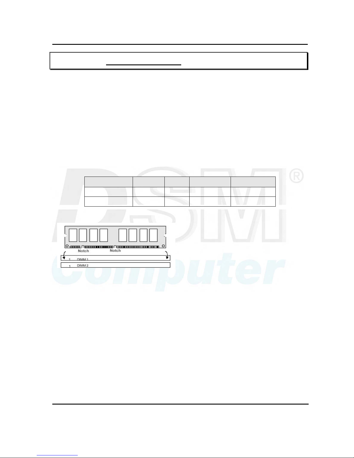
3-1 System Memory
The CPU board supports 2 slots for 168-pin 3.3V Non-registered DIMM modules, providing support for up to
512MB of main memory using DIMM modules from 8MB to 256MB. The following is the example to install
the system SDRAM memory module combination.
Note:
1. It is highly recommended to use the PC-100 or PC-133 Specification DIMM module.
2. Due to limitation of Intel 815E chipset, the board can’t support the ECC memory module.
Q’ty of Module DIMM1 DIMM2
Module Size
Max. Size
1 1 st 8~256 MB 256 MB
2 1 st 2 nd 8~256 MB 512 MB
To insert the DIMMs, the modules must be oriented in
the correct way. Notice the notches of the DIMM.
Align these notches as shown in the diagram below.
Gently push the DIMM until the retainers on both
sides of the socket lock the module in place.
To remove a DIMM, push the retainers outwards to
release the module then pull the module out of the
socket.

User's Guide Revision. B3 April, 2001
Capability Expand
3-7
3-2 Change CPU
To change the CPU, pull the handling bar of the socket upward to the other end to loosen the socket's
openings. Carefully lift the existing CPU up to remove it from the socket.
Removing CPU
Place the new CPU on the middle of the socket, orienting its beveled corner to line up with the socket's
beveled corner. Make sure the pins of the CPU fit evenly to the socket openings. Replace the handling
bar to fasten the CPU to the socket. Be sure to re-arrange the jumper setting for the correct external clock.
Installing CPU

User's Guide Revision. B3 April, 2001
BIOS Setup
4-1
Chapter 4 AWARD BIOS Setup
Award's BIOS ROM has a built-in Setup program that allows users to modify the basic system configuration.
This type of information is stored in battery-backed RAM (CMOS RAM) so that it retains the Setup
information when the power is turned off.
4-1 BIOS Setup
Entering Setup
Power on the computer and press <Del> immediately will allow you to enter Setup. The other way to
enter Setup is to power on the computer, when the below message appears briefly at the bottom of the
screen during the POST (Power On Self Test), press <Del> key or simultaneously press <Ctrl>, <Alt>,
and <Esc> keys.
TO ENTER SETUP BEFORE BOOT
PRESS <CTRL-ALT-ESC> OR <DEL> KEY
If the message disappears before you respond and you still wish to enter Setup, restart the system to try
again by turning it OFF then ON or pressing the "RESET" button on the system case. You may also
restart by simultaneously pressing <Ctrl>, <Alt>, and <Delete> keys. If you do not press the keys at the
correct time and the system does not boot, an error message will be displayed and you will again be
asked to,
PRESS <F1> TO CONTINUE,
<CTRL-ALT-ESC> OR <DEL> TO ENTER SETUP
User's Guide Revision. B3 April, 2001
BIOS Setup
4-2
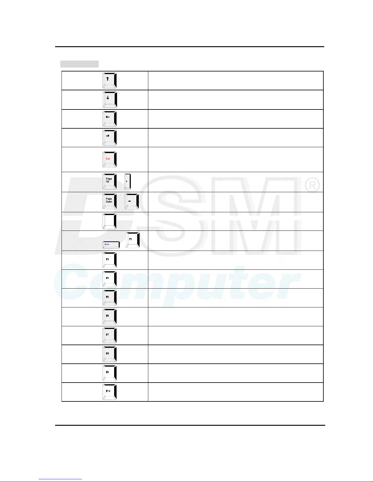
Control Keys
Up arrow
Move to previous item
Down arrow
Move to next item
Left arrow
Move to the item in the left hand
Right arrow
Move to the item in the right hand
Esc key
Main Menu -- Quit and not save changes into CMOS
Status Page Setup Menu and Option Page Setup Menu -- Exit
current page and return to Main Menu.
PgUp / “+” key
/
Increase the numeric value or make changes
PgDn / “−“ key
/
Decrease the numeric value or make changes
F1 key
F1
General help, only for Status Page Setup Menu and Option Page
Setup Menu
(Shift)F2 key
( )
Change color from total 16 colors. F2 to select color forward,
(Shift) F2 to select color backward
F3 key
Reserved
F4 key
Reserved
F5 key
Restore the previous CMOS value from CMOS, only for Option
Page Setup Menu
F6 key
Load the default CMOS value from BIOS default table, only for
Option Page Setup Menu
F7 key
Load the Setup default value, only for Option Page Setup Menu
F8 key
Reserved
F9 key
Reserved
F10 key
Save all the CMOS changes, only for Main Menu
Table 4-1 Control Keys

User's Guide Revision. B3 April, 2001
BIOS Setup
4-3
Getting Help
Main Menu
The on-line description of the highlighted setup function is displayed at the bottom of the screen.
Status Page Setup Menu/Option Page Setup Menu
Press <F1> to pop up a small help window that describes the appropriate keys to use and the possible
selections for the highlighted item. To exit the Help Window press <F1> or <Esc>.
User's Guide Revision. B3 April, 2001
BIOS Setup
4-4
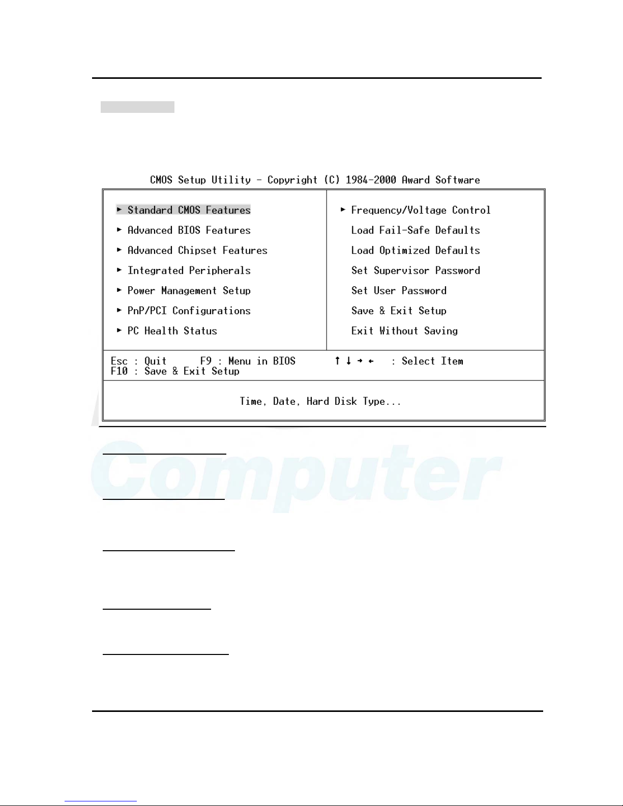
The Main Menu
Once you enter Award BIOS CMOS Setup Utility, the Main Menu (Figure 1) will appear on the screen.
The Main Menu allows you to select from ten setup functions and two exit choices. Use arrow keys to
select among the items and press <Enter> to accept or enter the sub-menu.
Standard CMOS Features
Use this menu for basic system configuration. See Page 4-6 for details.
Advanced BIOS Features
Use this menu to set the Advanced Features available on your system. See Page 4-9 for details.
Advanced Chipset features
Use this menu to change the values in the chipset registers and optimize your system's performance.
See Page 4-13 for details.
Integrated Peripherals
Use this menu to specify your settings for integrated peripherals. See Page 4-17 for details.
Power Management setup
Use this menu to specify your settings for power management See Page 4-21 for details.

User's Guide Revision. B3 April, 2001
BIOS Setup
4-5
PnP/PCI Configuration
This entry appears if your system supports PnP / PCI Configuration. See Page 4-25 for details.
PC health Status
Display CPU/System Temperature, Fan speed and Voltages Value. See Page 4-27 for details.
Frequency/Voltage Control
Use this menu to specify your settings for frequency/voltage control. See Page 4-28 for details.
Load Fail-Safe Defaults
Use this menu to load the BIOS default values for the minimal/stable performance for your system to
operate.
Load Optimized Defaults
Use this menu to load the BIOS default values that are factory settings for optimal performance system
operations. While Award has designed the custom BIOS to maximize performance, the factory has the
right to change these defaults to meet their needs.
Set Supervisor/User Password
Change, set, or disable password of supervisor or user. It allows you to limit access to the system and
Setup, or just to Setup. See Page 4-29 for details.
Save & Exit Setup
Save CMOS value changes to CMOS and exit setup.
Exit Without Saving
Abandon all CMOS value changes and exit setup.
User's Guide Revision. B3 April, 2001
BIOS Setup
4-6
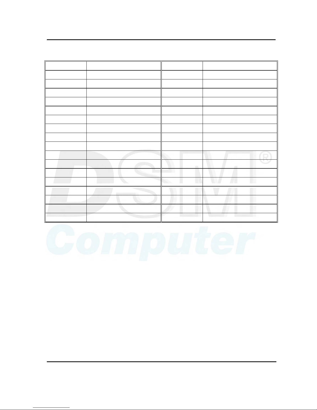
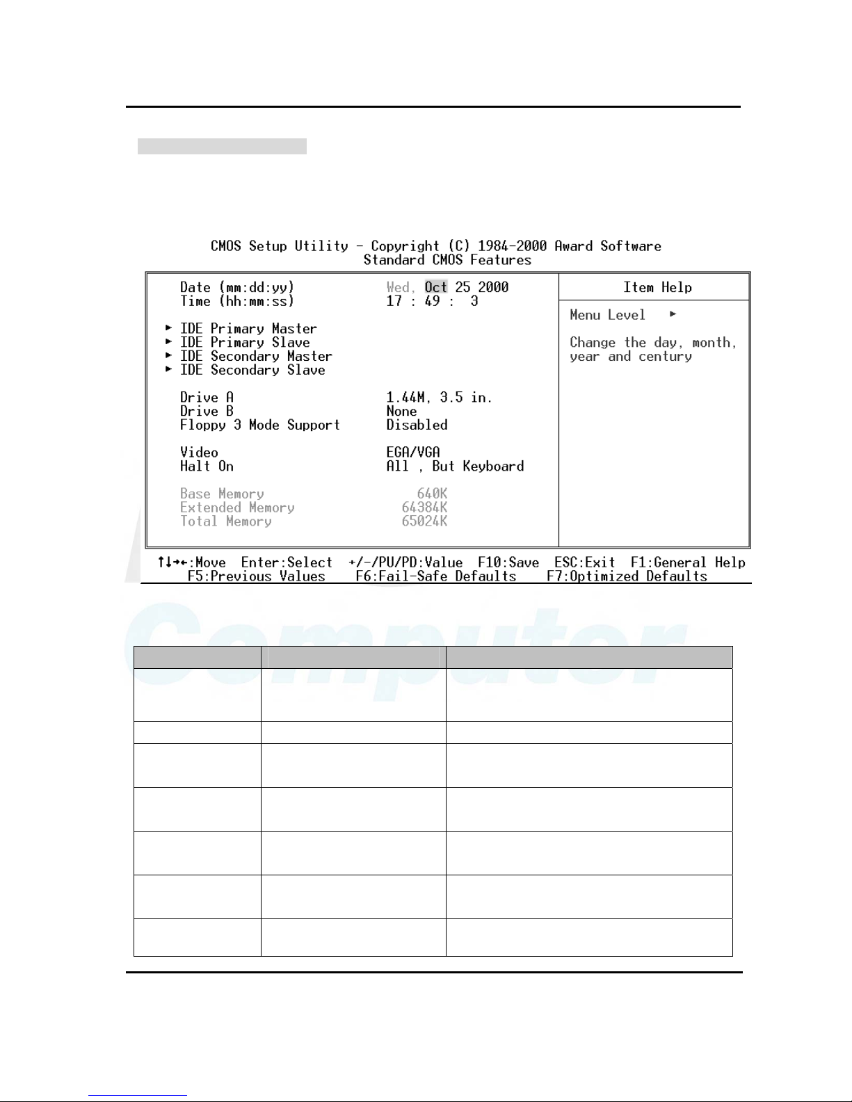
Standard CMOS Features
The items in Standard CMOS Setup Menu are divided into 11 categories. Each category includes no,
one or more than one setup items. Use the arrow keys to highlight the item and then use the <PgUp> or
<PgDn> keys to select the value you want in each item.
Main Menu Selections
Item Options Description
Date MMM DD YYYY
Set the system date. Note that the ‘Week
day’ automatically changes when you set the
date
Time HH : MM : SS Set the system time
IDE Primary Master
Options are in its sub menu
(Described in Table 4-3)
Press <Enter> to enter the sub menu of
detailed options
IDE Primary Slave
Options are in its sub menu
(Described in Table 4-3)
Press <Enter> to enter the sub menu of
detailed options
IDE Secondary
Master
Options are in its sub menu
(Described in Table 4-3)
Press <Enter> to enter the sub menu of
detailed options
IDE Secondary
Slave
Options are in its sub menu
(Described in Table 4-3)
Press <Enter> to enter the sub menu of
detailed options
Drive A None
Select the type of floppy disk drive installed in
your system
 Loading...