

DSM VF-150 OEM User Manual
114 Southeast Parkway Ct.
Ste 160
Franklin, TN 37064
Tel: 615/595-6665
Fax: 615/595-6610
Ma0
VF-150 OEM
LINEAR AMPLIFIER
USER MANUAL
DYNAMIC STRUCTURES AND MATE R IA L S, LLC
HARDWARE VERSION V131028, MANUAL VERSION V131118
Hardware Version V131028 1
114 Southeast Parkway Ct.
Ste 160
Franklin, TN 37064
Tel: 615/595-6665
Fax: 615/595-6610
VF-150 OEM
Please review the following points for both personal and equipment safety while operating the
linear piezoelectric amplifier.
HIGH ENERGY/VOLTAGE WA R N I N G S
Exercise caution when using amplifiers. High energy levels can be
stored at the output voltage terminals on all amplifiers in normal
operations. In addition, potentially lethal voltages exist in the power
circuit and the “output” connector. Filter capacitors store potentially
dangerous energy for some time after power is removed.
OPERATING AND SERVICES PRECAUTIONS
Operate the amplifier in an environment free of flammable gases or fumes. Do not use substitute
parts or make any unauthorized modifications to the amplifier to ensure that its safety features
are not degraded. Contact DSM for service and repair assistance.
SPECIFICATIONS
• Typical Output Voltages: -100 to +100 V
-40 to +200 V
-30 to +150 V
-20 to +120 V
Output range will be V
Neg Rail
+ 5V to V
Pos Rail
– 5V
• Maximum Continuous Current: 150 mA (Capacitive load)
• Maximum Peak Current: 300 mA (Capacitive load)
• Gain V/V ~58 +/- 5% (see AGA command)
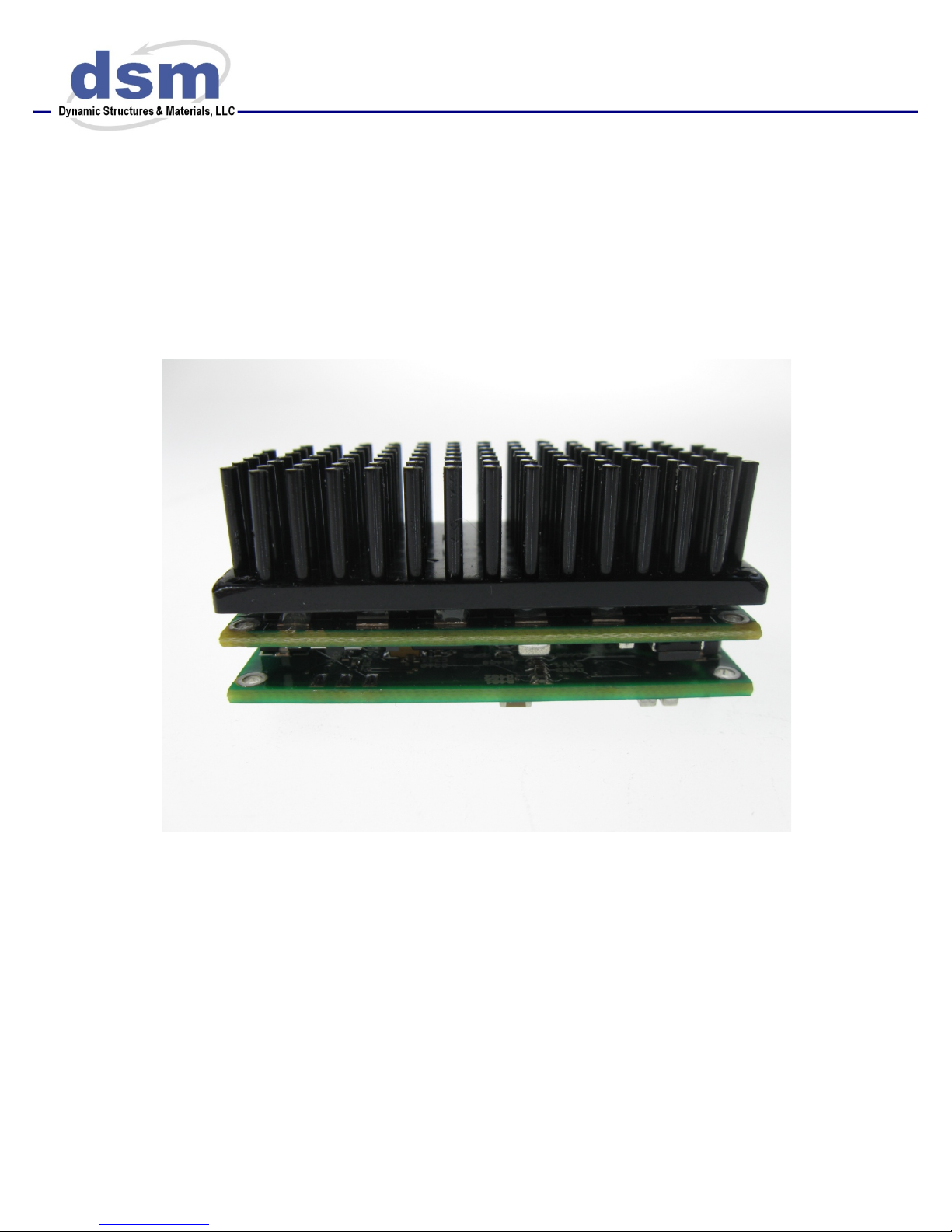
• Dimensions: L x W x H 2.0” x 1.0” x 0.5” (50.8mm x 25.4mm x 12.7mm)
• Dimensions: L x W x H with heat sink 2.0” x 1.0” x 1.0” (50.8mm x 25.4mm x 25.4mm)
• Amplifier bandwidth: ~10 kHz (-3dB)
• Electrical Noise on Output: ~1mVrms (power supply dependent)
• Short circuit, over-current, and over-temperature protection
• Connectors: FCI 10106813-021112LF
FCI 10106813-041112L
!
CAUTION
RISK OF DANGER

Hardware Version V131028 2
114 Southeast Parkway Ct.
Ste 160
Franklin, TN 37064
Tel: 615/595-6665
Fax: 615/595-6610
WA R N I N G !
General Precautions
♦ All insulation of leads connected to output terminals should have at least a 300V rating.
♦ Do not use clip leads in the connections. They are very dangerous for high-voltage work.
Acceptable Load Types
♦ This Amplifier is designed to drive capacitive loads only. Do not use with resistive loads.
The driver will only work properly when a capacitive load is connected to the output.
♦ Never connect an inductive or a resistive load to the unit. This would cause a short-lived
high-current pulse at the output and would damage the unit.
Short Circuit Damage
♦ Although the VF-150 OEM is protected against a short circuit on the output, it is
recommended that a short circuit condition be avoided.
♦ Never connect an "earth ground" lead (e.g., an oscilloscope ground lead) to the output
terminal. This can cause high current at the output and possible damage to the unit.
♦ If the user desires to observe the output signals using a voltage meter or an oscilloscope, the
user must ensure that the meter or oscilloscope has an input impedance of at least 1 MΩ.
Smaller input impedances could damage the unit.
RECOMMENDED OPERATION
Intended Use
DSM’s VF-150 OEM is intended to drive piezoelectric (capacitive) loads of the following types:
• Operating range –100 to +100 V
• Operating range –40 to +200 V
• Operating range –30 to +150 V
• Operating range –20 to +120 V
External power supply determines configuration. The input rail voltages should both be 5 to 10
Volts beyond the operating range. For example if -30 to +150 Volt operation is requred, typical
rail voltages would be -40 and +160 Volts. Two modes of operation are supported; the output
voltage can be set using an analog input voltage with nominal gain of 58, or the output voltage
can be set using a serial communication interface. Operation is decribed in more detail, below.
 Loading...