

DSM 96M4371o User Manual

96M4371o
Single Board Computer
User's Manual
Version 1.1
Copyright © DSM Computer GmbH, 2011. All rights reserved.
All other brand names are registered trademarks of their respective owners.

Preface
96M4371o User’s Manual 1-1
Table of Contents
How to Use This Manual
Chapter 1 System Overview.......................................................................................................1-1
1.1 Introduction ....................................................................................................... 1-1
1.2 Check List........................................................................................................... 1-2
1.3 Product Specification........................................................................................ 1-3
1.3.1 Mechanical Drawing................................................................................ 1-6
1.4 System Architecture.......................................................................................... 1-8
Chapter 2 Hardware Configuration ...........................................................................................2-1
2.1 Jumper Setting................................................................................................... 2-1
2.2 Connector Allocation........................................................................................ 2-2
Chapter 3 System Installation....................................................................................................3-1
3.1 Intel® i7/i5/P4500 PGA ..................................................................................3-1
3.2 Main Memory .................................................................................................... 3-1
3.3 Installing the Single Board Computer............................................................ 3-2
3.3.1 Chipset Component Driver .................................................................... 3-2
3.3.2 Intel® Integrated HD Graphics Controller........................................... 3-2
3.3.3 Intel Gigabit Ethernet Controller ........................................................... 3-3
3.3.4 Audio Controller...................................................................................... 3-3
3.4 Clear CMOS Operation .................................................................................... 3-3
3.5 WDT Function ................................................................................................... 3-3
3.6 GPIO.................................................................................................................. 3-10
3.6.1 Pin assignment ....................................................................................... 3-10
3.6.2 96M4371o GPIO Programming Guide ...............................................3-10
3.6.3 Example................................................................................................... 3-11
Chapter 4 BIOS Setup Information............................................................................................4-1
4.1 Entering Setup -- Launch System Setup ........................................................ 4-1
4.2 Main .................................................................................................................... 4-2
4.3 Advanced ........................................................................................................... 4-3
4.4 Chipset.............................................................................................................. 4-28
4.5 Boot ................................................................................................................... 4-35
4.6 Security ............................................................................................................. 4-38
4.7 Save & Exit ....................................................................................................... 4-39
Chapter 5 Troubleshooting........................................................................................................5-1
5.1 Hardware Quick Installation........................................................................... 5-1
5.2 BIOS Setting ....................................................................................................... 5-2
5.3 FAQ ..................................................................................................................... 5-4
Appendix A
Appendix B

Preface
96M4371o User’s Manual 1-2
How to Use This Manual
The manual describes how to configure your 96M4371o system to meet
various operating requirements. It is divided into five chapters, with each chapter
addressing a basic concept and operation of Single Board Computer.
Chapter 1 : System Overview. Presents what you have in the box and give you an
overview of the product specifications and basic system architecture for this model of
single board computer.
Chapter 2 : Hardware Configuration. Shows the definitions and locations of Jumpers
and Connectors that you can easily configure your system.
Chapter 3 : System Installation. Describes how to properly mount the CPU, main
memory and M-systems flash disk to get a safe installation and provides a
programming guide of Watch Dog Timer function.
Chapter 4 : BIOS Setup Information. Specifies the meaning of each setup
parameters, how to get advanced BIOS performance and update new BIOS. In
addition, POST checkpoint list will give users some guidelines of trouble-shooting.
Chapter 5 : Troubleshooting. Provides you a few useful tips to quickly get your
96M4371o running with no failure. As basic hardware installation has been
addressed in Chapter 3, this chapter will basically focus on system integration issues,
in terms of backplane setup, BIOS setting, and OS diagnostics.
The content of this manual and EC declaration document is subject to change without
prior notice. These changes will be incorporated in new editions of the document.
DSM may make supplement or change in the products described in this document at
any time.
Updates to this manual, technical clarification, and answers to frequently asked
questions will be shown on the following web site : http://www.dsm-computer.com.

System Overview
96M4371o User’s Manual 1-1
Chapter 1
System Overview
1.1 Introduction
96M4371o, the PICMG 1.3 SHB (Single Host Board) combined with either
the Intel® Core i7-620M/i5-520M/P4500 processor. The attractive Core i processor
does not only posses amazing parallel computing power but also generates only 35W
TDP (Thermal Design Power). That makes the system more powerful and reliable
with smaller and quieter cooling fan.
The SHB adopted Intel® QM57 chipset. The QM57 embedded Graphics Media
Accelerator HD is the latest generation Intel integrated graphics controller that can
supports 3D multimedia capabilities including Microsoft DirectX 10, Shader Model
4.0, MPEG-2 and OpenGL 2.1. More than that, user could utilize even higher-end, the
latest PCI Express x16 interface graphics card via backplane. Based on the
low-power/high-performance Nehalem micro-architecture, the processor is designed
for a two-chip platform, as opposed to the traditional three chip platforms (processor,
GMCH, and ICH).
96M4371o built with dual Intel® Gigabit Ethernet. Two DDR3 DIMM
sockets support system memory up to 8GB. Six SATA 300 ports (dual ports via
backplane) support RAID 0, 1, 5, 10.
To meet bandwidth of storage and expansion cards requirement, the
96M4371o was designed flexible with five PCI Express lanes via backplane.
Those PCI Express lanes could be one PCI Express x16(or two PCI Express x8 links)
from CPU and four PCI Express x1 links(or one PCI Express x4 link) from PCH. Four
PCI Express x1 links configuration can support more PCI Express x1 devices via
backplane and one PCI Express x4 link configuration can support RAID card or
special add-on cards such as image processing board. In addition, the flexible
configuration can be leveraged with bridge on backplane to support more PCI or
PCI-X slots that benefits industries with legacy support.
Advanced Management Technology (AMT) 6.0 is feature that 96M4371o
equipped. This technology provides remote access capability via Intel® Gigabit
Ethernet controller. The new technology is a hardware-based solution that uses
out-of-band communication for system management access to client systems. Beside
that, the hardware and software information can be gathering by 3rd party software
then storage in SPI interface EEPROM. Therefore, asset management could be done
at the same time. 96M4371o also supports iTPM (Intel Trusted Platform Module) function for applications.

System Overview
96M4371o User’s Manual 1-2
96M4371o features:
z Support Intel i7-620M/i5-520M/P4500 processors in rPGA988 package
z Delivers up to 8GB maximum DDR3 1066/800 on two DIMM sockets
z Support dual display by DVI-I port on bracket
z Support iAMT 6.0 and external TPM via TPM module
z High speed dual Gigabit Ethernet based on PCI Express x1, high bandwidth I/
O interface
z Rich I/O connections such as FDD, two Gigabit Ethernet, serial ports, paral-
lel port, USB 2.0
z Four on-board SATA ports support RAID 0,1,5,10
The PICMG 1.3 SHB is the best solution of applications such like flight simulation,
image processing, broadcasting and so on that need performance of display and
storage.
1.2 Check List
The 96M4371o package should cover the following basic items:
z One 96M4371o single host board
z One dual Serial ports cable kit
z One single Parallel port cable kit
z One FDD cable
z Two 7-pin SATA signal cables
z One DVI-I cable
z One Installation Resources CD-Title
Optional: One bracket with PS/2 keyboard and mouse
If any of these items is damaged or missing, please contact your vendor and keep all
packing materials for future replacement and maintenance.

System Overview
96M4371o User’s Manual 1-3
1.3 Product Specification
z Main processor
- Intel® Core i7-620M/i5-520M/P4500 Processor
z BIOS
AMI system BIOS with SPI Serial CMOS EEPROM with easy upgrade function ACPI,
DMI, Green function and Plug and Play Compatible
z Main Memory
- Support dual-channel DDR3 memory interface
- Non-ECC, non-buffered DIMMs only
- Two DIMM sockets support 1066/800 DDR3-SDRAM up to 8GB System Memory
z L2 Cache Memory
Built-in Processor
z Chipset
Intel® QM57 chipset
z Bus Interface
- Follow PICMG 1.3 Rev 1.0 standard (PCI Express and PCI)
- Support four PCI Express x1 (can be aggregated as one PCI Express x4) through
backplane
- Support one PCI Express x16(can be separated as two PCI Express x8) through
backplane
- Support four PCI devices through backplane
z SATA
- Four SATA 300 ports on-board and dual SATA 300 ports via backplane
- Support Intel® Matrix Storage Technology based on Intel® QM57
z Floppy Drive Interface
Support one FDD port up to two floppy drives and 5-1/4"(360K, 1.2MB), 3-1/2"
(720K, 1.2MB, 1.44MB, 2.88MB) diskette format and 3-mode FDD
z Serial Ports
Support two high-speed 16C550 compatible UARTs with 16-byte T/R FIFOs
z Parallel Port
Support one parallel port with SPP, EPP and ECP modes

System Overview
96M4371o User’s Manual 1-4
z USB Interface
Support twelve USB (Universal Serial Bus) ports (two USB ports on bracket that
dedicated to keyboard & mouse; six USB ports on-board and four USB ports via
backplane) for high-speed I/O peripheral devices
z PS/2 Mouse and Keyboard Interface
Support one 10-pin header for external PS/2 keyboard/mouse connection
z Auxiliary I/O Interfaces
System reset switch, external speaker, Keyboard lock and HDD active LED, etc
z Real Time Clock/Calendar (RTC)
Support Y2K Real Time Clock/Calendar with battery backup for 7-year data
retention
z Watchdog Timer
- Support WDT function through software programming for enable/disable and
interval setting
- Generate system reset
z On-board VGA
GMCH integrated graphics, 400MHz core frequency; share system memory up to
1GB for system with greater than or equal to 192MB of system memory
z On-board Ethernet LAN
Dual Intel® PCI Express x1 interface based Gigabit Ethernet to support RJ-45
connector
z High Driving GPIO
Support 8 programmable high driving GPIO
z Cooling Fans
Support one 4-pin power connector for CPU fan and one 3-pin power connector for
system fan
z System Monitoring Feature
Monitor CPU temperature, system temperature and major power sources, etc.
z Bracket
Support dual Ethernet port with 2 indicators, dual USB ports and one DVI port
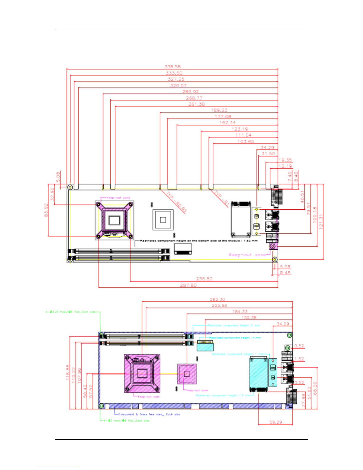
z Outline Dimension (L X W):
338.5mm (13.33”) X 126.39mm (4.98”)
System Overview
96M4371o User’s Manual 1-5
z Power Requirements:
- +12V (CPU)@ 1.37A
- +12V (System)@ 0.31A
- +5V @ 3.58A
- Test Programs: BurnIn Test V5.3
- Run Time: Full loading
z - Test configuration:
System Configuration
CPU Type
Intel® Core™ i7 CPU M620 @2.67GHz L3:4MB Bus Speed:133
SBC BIOS
96M4371o BIOS Rev.: R1.00.E0 (07142010)
Memory
DDR3 1066 1GB (ELPIDA J1108BABG-DJ-E)
VGA Card
Onboard Intel® QM57
VGA Driver
Intel® Graphics Media Accelerator HD Version 6.14.10.5189
LAN Card #1
Onboard Intel® 82577LM Gigabit Network Connection
LAN Driver
Intel® 82577LM Gigabit Network Connection Version 11.5.10.0
LAN Card #2
Onboard Intel® 82583V Gigabit Network Connection
LAN Driver
Intel® 82583V Gigabit Network Connection Version 11.4.7.0
Audio Card
Onboard Realtek ALC662 Audio
Audio Driver
Realtek High Definition Audio Version 5.10.0.5043
Chip Driver
Intel® Chipset Device Software Version 9.1.1.1025
SATA HDD
Seagate ST3808110AS 80GB
CDROM
LITE-ON LH-20A1S DVD-ROM
Power Supply
Sunpower SPX-6500P1 500W
Back plane
13 slot
z Operating Temperature:
0°C ~ 60°C (23°F ~ 140°F)
z Storage Temperature:
-20°C ~ 80°C
z Relative Humidity:
5% ~ 90%, non-condensing
System Overview
96M4371o User’s Manual 1-6
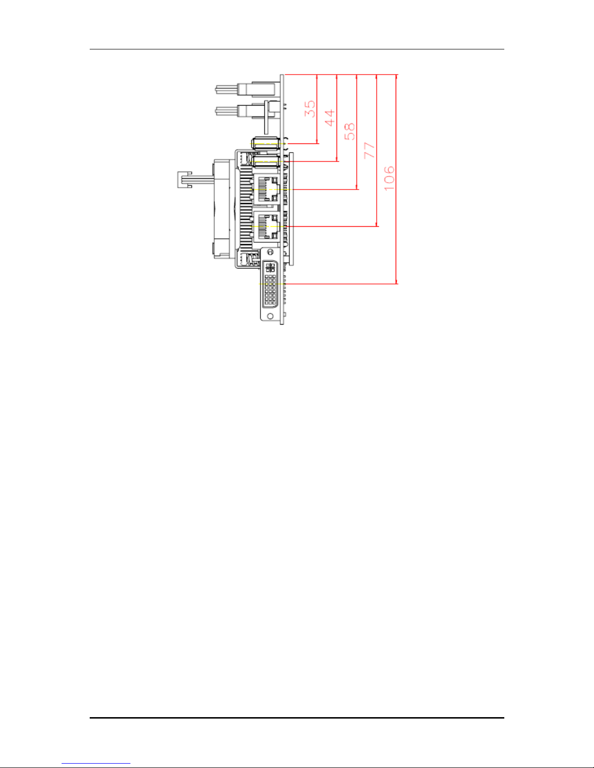
1.3.1 Mechanical Drawing
System Overview
96M4371o User’s Manual 1-7
System Overview
96M4371o User’s Manual 1-8
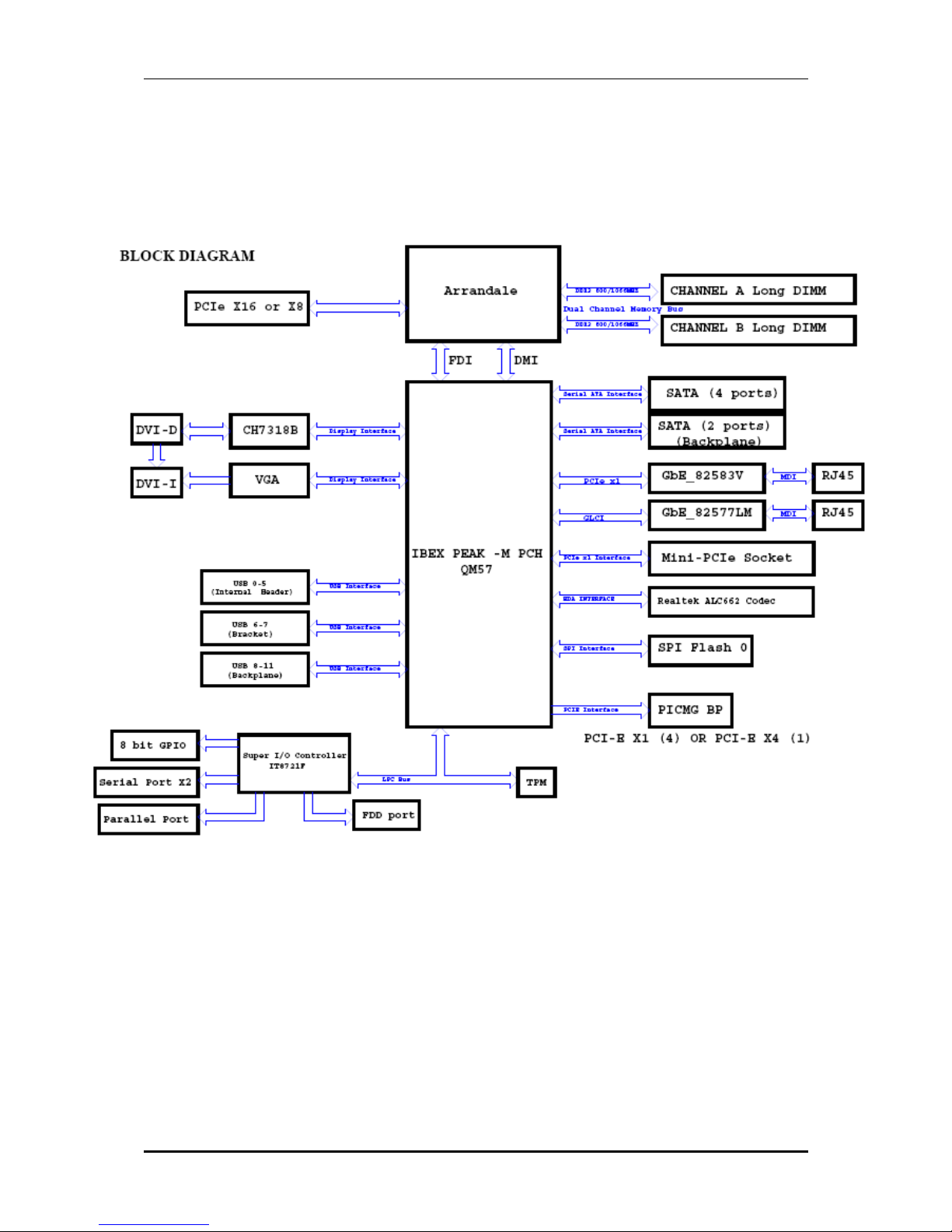
1.4 System Architecture
All of details operating relations are shown in 96M4371o series System
Block Diagram
96M4371o System Block Diagram

Hardware Configuration
96M4371o User’s Manual 2-1
Chapter 2
Hardware Configuration
This chapter indicates jumpers’, headers’ and connectors’ locations. Users may find
useful information related to hardware settings in this chapter. The default settings
are indicated with a star sign (Ì).
2.1 Jumper Setting
In the following sections, Short means covering a jumper cap over jumper pins; Open
or N/C (Not Connected) means removing a jumper cap from jumper pins. Users can
refer to Figure 2-1 for the Jumper locations.
Figure 2-1 96M4371o Jumper and Connector Locations
The jumper settings are schematically depicted in this manual as follows:
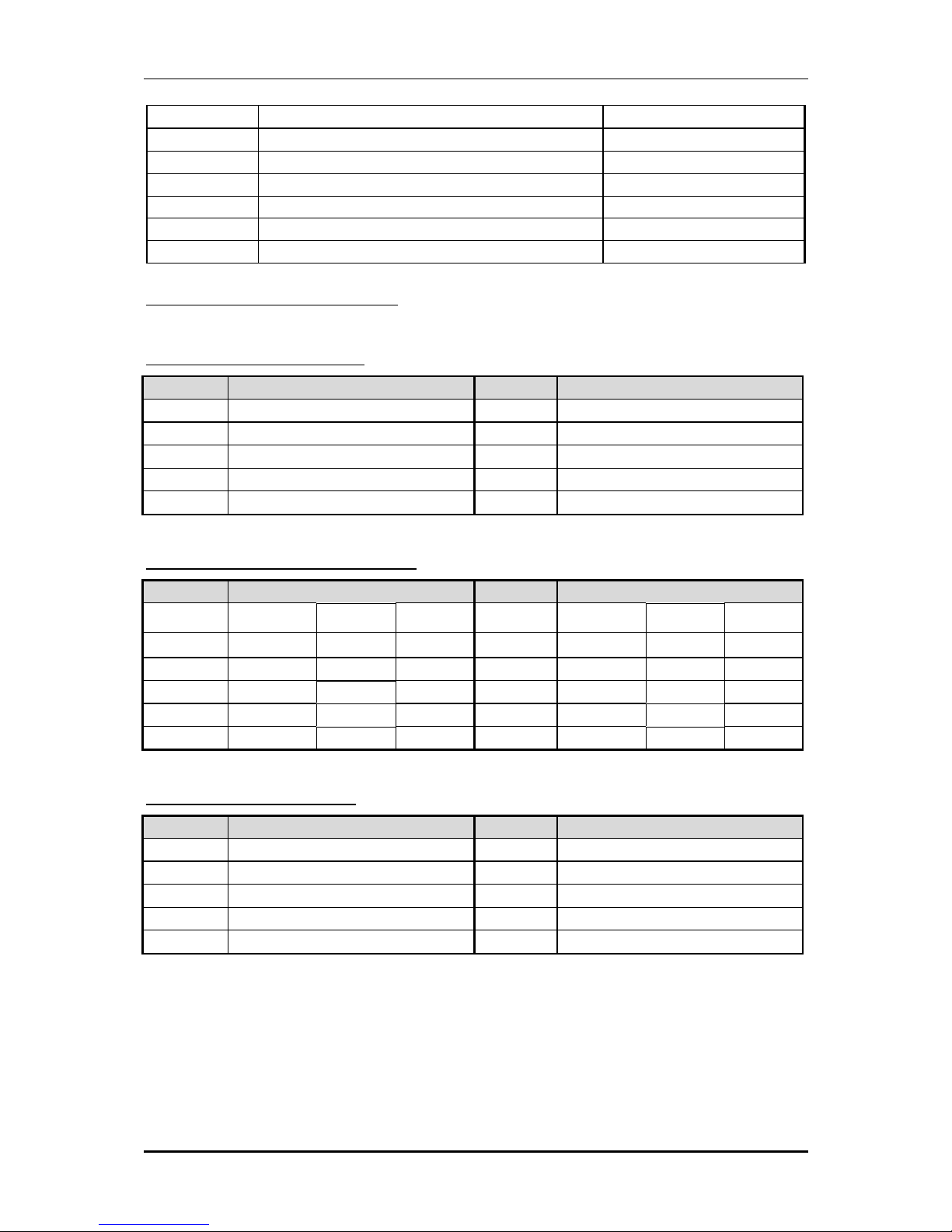
JP1: COM2 RS232, 422, 485 Selection
JP1 Function
5-6,9-11,10-12,15-17,16-18 Short RS-232
3-4,7-9,8-10,13-15,14-16,21-22 Short RS-422
1-2,7-9,8-10,19-20 Short RS-485
JP3: CMOS Clear Header
JP3 Function
1-2 Open Normal Operation
1-2 Short Clear CMOS Contents
Hardware Configuration
96M4371o User’s Manual 2-2
JP5: PCI_VIO_Selection
JP5 Function
1-2 Short VCC3
2-3 Short VCC
JP7: PCI_Express X16 X8_Selection
JP7 Function
1-2 Open 1 x16 PEG
1-2 Short 2 x8 PEG
J35: Auto Power On_Selection
J35 Function
1-2 Open Normal
1-2 Short Auto Power On
2.2 Connector Allocation
I/O peripheral devices are connected to the interface connectors.
Connector Function List
Connector Function Remark
J
P6 LPC Debug Pin header
J
1 COM2 Pin Header
J
2 COM1 Pin Header
J
3 Parallel Port Pin Header
J
4 DDR3 CHB Slot
J
5 FDC Interface Pin Header
J
6 8-bit GPIO Pin Header
J
7 PS2 KB/MS Pin Header
J
8 IR Pin Header
J
9 HDD LED Pin Header
J
10 SUS LED Pin Header
J
11 TPM Pin Header
J
12 Buzzer Pin Header
J
13 DDR3 CHA Slot
J
14 Audio MIC/Line-in/Line-out Pin Header
J
15 LAN LED Pin Header
J
16,J17,J18 USBx2 Pin Header
J
20,J24 Rear USB Connector
J
21,J22,J25,J26 SATA CONNECTOR
J
23 ATX 4P CONNECTOR
Hardware Configuration
96M4371o User’s Manual 2-3
J
27, J29 LAN CONNECTOR
J
28 Mini-PCI Express socket
J
30 Second SPI Pin Header
J
31 SM_BUS Pin Header
J
33 DVI-I Connector
J
34 CPU FAN Pin Header
J
36 SYS FAN Pin Header
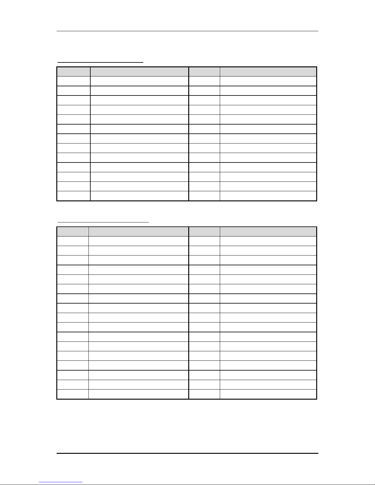
Pin Assignments of Connectors
JP6: LPC Debug Pin header
PIN No. Signal Description PIN No. Signal Description
1 LAD0 2 VCC3
3 LAD1 4 PLT_RST#
5 LAD2 6 LFRAME#
7 LAD3 8 CLOCK
9 KEY 10 GND
J1 : COM2 232/422/485 Pin Header
PIN No. Signal Description PIN No. Signal Description
RS-232 RS-422 RS-485
RS-232 RS-422 RS-485
1 DCD# TX- DATA- 2 DSR# TX+ DATA+
3 RXD# RX+ N/C 4 RTS# RX- N/C
5 TXD# GND GND 6 CTS# N/C N/C
7 DTR# N/C N/C 8 RI# N/C N/C
9 GND N/C N/C 10 NC N/C N/C
J2: COM1 Port Pin Header
PIN No. Signal Description PIN No. Signal Description
1 DCD# 2 DSR#
3 RXD# 4 RTS#
5 TXD# 6 CTS#
7 DTR# 8 RI#
9 GND 10 NC
Hardware Configuration
96M4371o User’s Manual 2-4
J3: Parallel Port Pin Header
PIN No. Signal Description PIN No. Signal Description
1 Strobe# 2 Auto Form Feed#
3 Data 0 4 Error#
5 Data 1 6 Initialization#
7 Data 2 8 Printer Select IN#
9 Data 3 10 Ground
11 Data 4 12 Ground
13 Data 5 14 Ground
15 Data 6 16 Ground
17 Data 7 18 Ground
19 Acknowledge# 20 Ground
21 Busy 22 Ground
23 Paper Empty 24 Ground
25 Printer Select 26 N/C
J5: FDC Interface Pin Header
PIN No. Signal Description PIN No. Signal Description
1 Ground 2 Density Select 0
3 Ground 4 NC
5 KEY 6 NC
7 Ground 8 Index#
9 Ground 10 Motor ENA#
11 Ground 12 NC
13 Ground 14 Drive Select A#
15 Ground 16 NC
17 Ground 18 Direction#
19 Ground 20 Step#
21 Ground 22 Write Data#
23 Ground 24 Write Gate#
25 Ground 26 Track 0#
27 Ground 28 Write Protect#
29 NC 30 Read Data#
31 Ground 32 Head Select#
33 NC 34 Disk Change#
Hardware Configuration
96M4371o User’s Manual 2-5
J6: 8-bit GPIO
PIN No. Signal Description PIN No. Signal Description
1 GPIO11 2 GPIO32
3 GPIO12 4 GPIO33
5 GPIO30 6 GPIO36
7 GPIO31 8 GPIO37
9 GND 10 VCC
J7: PS2 KB/MS Pin Header
PIN No. Signal Description PIN No. Signal Description
1 Mouse Data 2 Keyboard Data
3 KEY 4 KEY
5 GND 6 GND
7 PS2 Power 8 PS2 Power
9 Mouse Clock 10 Keyboard Clock
J8: IR Pin Header
PIN No. Signal Description
1 VCC
2 NC
3 IRRX
4 GND
5 IRTX
6 NC
J9: HDD LED Pin Header
Pin No. Signal Description
1 VCC(pull up 330 ohm)
2 HD_LED#
J10: SUS LED Pin Header
Pin No. Signal Description
1 5VSB(pull up 330 ohm)
2 SUS_LED#
Hardware Configuration
96M4371o User’s Manual 2-6
J11: TPM Pin Header
PIN No. Signal Description PIN No. Signal Description
1 Clock 2 GND
3 LFRAME# 4 NC
5 PLT_RST# 6 VCC
7 LAD3 8 LAD2
9 VCC3 10 LAD1
11 LAD0 12 GND
13 SMB_CLK 14 SMB_DATA
15 3V_DUAL 16 SERIRQ
17 GND 18 NC
19 NC 20 NC
J12: Buzzer Pin Header
PIN No. Signal Description
1 VCC
2 NC
3 NC
4 BUZZER
J14: Audio MIC/Line-in/Line-out Pin Header
PIN No. Signal Description PIN No. Signal Description
1 MIC with Reference Voltage 2 Analog GND
3 Line-in Left Channel 4 Analog GND
5 Line-in Right Channel 6 Analog GND
7 Line-out Left Channel 8 Analog GND
9 Line-out Right Channel 10 KEY
J15: Buzzer Pin Header
PIN No. Signal Description
1 +V3.3M(pull up 330 ohm)
2 82577LM_Active#
3 82583V_Active#
4 3V_DUAL(pull up 330 ohm)
Hardware Configuration
96M4371o User’s Manual 2-7
J16 & J17 & J18: USBx2 Pin Header
PIN No. Signal Description PIN No. Signal Description
1 5V_DUAL 2 5V_DUAL
3 DATA - 4 DATA 5 DATA + 6 DATA +
7 GND 8 GND
9 KEY 10 GND
J30: Second SPI Pin Header
PIN No. Signal Description PIN No. Signal Description
1 SPI_CS#1 2 +V3.3M
3 SPI_SO 4 SPI_CLK
5 GND 6 SPI_SI
J31: SM_BUS Pin Header
PIN No. Signal Description
1 SMB_CLK
2 NC
3 GND
4 SMB_DATA
5 VCC
J34: CPU Fan Pin Header
Pin No. Signal Description
1 GND
2 +12V
3 PWM_CONTROL
4 SENSE
J36: SYS FAN Pin Header
Pin No. Signal Description
1 PWM_CONTROL
2 +12V
3 SENSE

System Installation
96M4371o User’s Manual 3-1
Chapter 3
System Installation
This chapter provides you with instructions to set up your system. The additional
information is enclosed to help you set up onboard PCI device and handle Watch Dog
Timer (WDT) and operation of GPIO in software programming.
3.1 Intel® i7/i5/P4500 PGA
96M4371o has equipped the most advanced Intel® Core i7/i5/i3 series
CPUs which has built-in Intel® HD Graphics Controller providing a total solution of
multi-purpose operation.
Further more, the leading-edge Intel® Core™ processor delivers unmatched
technology for intelligent performance on the most demanding tasks, such as creating
digital video and playing intense games. With building into 96M4371o
module, it can be applied in many different uses depending on the function of carrier
board.
3.2 Main Memory
96M4371o provide 2 x 240pin Long-DIMM sockets which supports
800/1066 DDR3-SDRAM as main memory Non-ECC, non-register type of functions.
The maximum memory can be up to 8GB. Memory clock and related settings can be
detected by BIOS via SPD interface.
For system compatibility and stability, do not use memory module without brand.
Memory configuration can be set to either one double-sided DIMM in one DIMM
socket or two single-sided DIMM in both sockets.
Beware of the connection and lock integrity from memory module to socket. Inserting
improperly it will affect the system reliability.
Before locking, make sure that all modules have been fully inserted into the card
slots.
Single Channel DDR
Memory Frequency
Bandwidth
800 12.8 GB/s
1066 17 GB/s
CPU
Support List
Intel® Core i7-620M
Intel® Core i5-520M
Intel® P4500

System Installation
96M4371o User’s Manual 3-2
Note:
To insure the system stability, please do not change any of DRAM parameters in BIOS
setup to modify system the performance without acquired technical information.
3.3 Installing the Single Board Computer
To install your 96M4371o into standard chassis or proprietary environment,
please perform the following:
Step 1 : Check all jumpers setting on proper position
Step 2 : Install and configure CPU and memory module on right position
Step 3 : Place 96M4371o into the dedicated position in the system
Step 4 : Attach cables to existing peripheral devices and secure it
WARNING
Please ensure that SBC is properly inserted and fixed by mechanism.
Note:
Please refer to section 3.3.1 to 3.3.4 to install INF/VGA/LAN/Audio drivers.
3.3.1 Chipset Component Driver
96M4371o uses state-of-art Intel® QM57 chipset. It’s a new chipset that
some old operating systems might not be able to recognize. To overcome this
compatibility issue, for Windows Operating Systems such as Windows
XP/Vista/Win7, please install its INF before any of other Drivers are installed. You
can find very easily this chipset component driver in 96M4371o CD-title.
3.3.2 Intel® Integrated HD Graphics Controller
Unlike the other structure, 96M4371o has integrated HD Graphics derived from
Intel® Core series CPU (i5/i7). It’s the most advanced design to gain an outstanding
graphic performance. Shared 8 accompany it to 256MB system DDR3-SDRAM with
Total Graphics Memory. 96M4371o supports VGA, DVI. This combination
makes 96M4371o an excellent piece of multimedia hardware.
With no additional video adaptor, this onboard video will usually be the system
display output. By adjusting the BIOS setting to disable on-board VGA, an add-on
PCI-Express graphic card can take over the system display.
System Installation
96M4371o User’s Manual 3-3
Drivers Support
Please find all the drivers in the 96M4371o CD-title. Drivers support ,
Windows XP/Vista/Win7.
3.3.3 Intel Gigabit Ethernet Controller
Drivers Support
Please find INTEL 82577LM & 82583V LAN driver in /Ethernet directory of
96M4371o CD-title. The drivers support Windows XP/Vista/Win7.
3.3.4 Audio Controller
Please find Intel® High Definition Audio driver form 96M4371o CD-title.
The drivers support Windows XP/Vista/Win7.
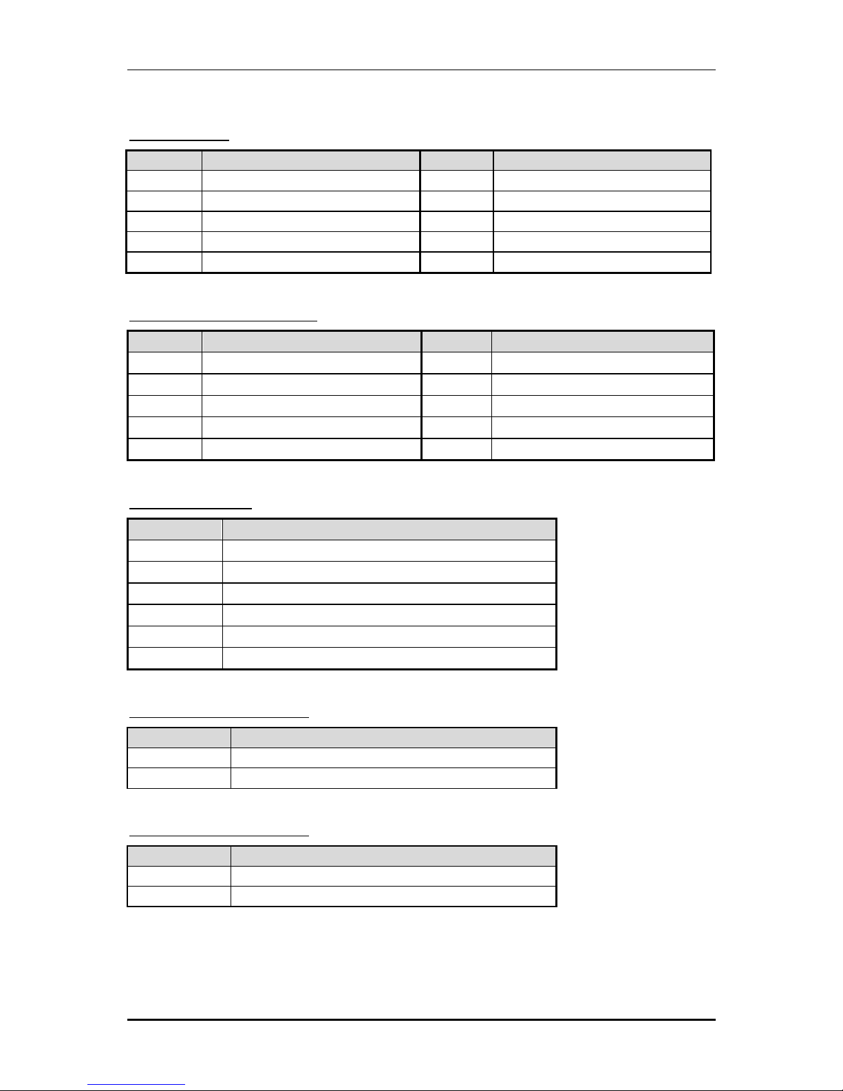
3.4 Clear CMOS Operation
The following table indicates how to enable/disable Clear CMOS Function hardware
circuit by putting jumpers at proper position.
JP3: CMOS Clear Header
Function
1-2 Open Normal Operation Ì
1-2 Short Clear CMOS Contents
3.5 WDT Function
The working algorithm of the WDT function can be simply described as a counting
process. The Time-Out Interval can be set through software programming. The
availability of the time-out interval settings by software or hardware varies from
boards to boards.
96M4371o allows users control WDT through dynamic software
programming. The WDT starts counting when it is activated. It sends out a signal to
system reset or to non-maskable interrupt (NMI), when time-out interval ends. To
prevent the time-out interval from running out, a re-trigger signal will need to be sent
before the counting reaches its end. This action will restart the counting process. A
well-written WDT program should keep the counting process running under normal
condition. WDT should never generate a system reset or NMI signal unless the
system runs into troubles.

System Installation
96M4371o User’s Manual 3-4
The related Control Registers of WDT are all included in the following sample
program that is written in Assembly language. User can fill a non-zero value into the
Time-out Value Register to enable/refresh WDT. System will be reset after the
Time-out Value to be counted down to zero. Or user can directly fill a zero value into
Time-out Value Register to disable WDT immediately. To ensure a successful
accessing to the content of desired Control Register, the sequence of following
program codes should be step-by-step run again when each register is accessed.
Additionally, there are maximum 2 seconds of counting tolerance that should be
considered into user’ application program. For more information about WDT, please
refer to ITE8721 data sheet.
There are two PNP I/O port addresses that can be used to configure WDT,
1) 0x2E:Test 1 Register
2) 0x2F:Test 2 Register
Below are some example codes, which demonstrate the use of WDT.
.model small
.386p
.stack
.data
ADDRESS dw 0FFFFh
.code
pgm:
mov ADDRESS,002eh ; I suppose 2Eh that is the address of SIO
mov dx, ADDRESS ; enter MB PnP mode in 2Eh
mov al, 87h
out dx, al
mov al, 01h
out dx, al
mov al, 55h
out dx, al
mov al, 55h
out dx, al
mov al, 20h ; read the Chip ID to check the address of SIO
out dx, al
inc dx
in al, dx ; default =87h
mov bl, al
mov al, 21h
mov dx, ADDRESS
out dx, al
inc dx

System Installation
96M4371o User’s Manual 3-5
in al, dx ; default =21h
mov bh, al
cmp bx, 2187h ;cmp CHIP ID
je L1
mov ADDRESS,4eh ; SIO in 4Eh
mov dx, ADDRESS ; enter MB PnP mode in 4Eh
mov al, 87h
out dx, al
mov al, 01h
out dx, al
mov al, 55h
out dx, al
mov al, 0AAh
out dx, al
mov al, 20h ; read the Chip ID to check the address of SIO
out dx, al
inc dx
in al, dx ; default =87h
mov bl, al
mov al, 21h
mov dx, ADDRESS
out dx, al
inc dx
in al, dx ; default =21h
mov bh, al
cmp bx, 2187h
je L1
xor bx, bx
mov ah, 0Eh
mov al, 'S'
int 10h
mov al, 'I'
int 10h
mov al, 'O'
int 10h
mov al, ' '
int 10h
mov al, 'F'

System Installation
96M4371o User’s Manual 3-6
int 10h
mov al, 'a'
int 10h
mov al, 'i'
int 10h
mov al, 'l'
int 10h
mov al, 0dh ;CR
int 10h
mov al, 0ah
int 10h ;LF
jmp stop
L1 :
mov dx, ADDRESS ;set WDT state
mov al, 07h
out dx, al
inc dx
out dx, al
mov dx, ADDRESS
mov al, 71h
out dx, al
inc dx
mov al, 00h
out dx, al
mov dx, ADDRESS
mov al, 72h
out dx, al
inc dx
mov al, 0C0h
out dx, al
xor bx, bx ; show the potion
mov ah, 0Eh
mov al, 'W'
int 10h
mov al, 'D'
int 10h
mov al, 'T'
int 10h
mov al, ':'
int 10h
mov al, 'T'
int 10h

System Installation
96M4371o User’s Manual 3-7
mov al, 'e'
int 10h
mov al, 's'
int 10h
mov al, 't'
int 10h
mov al, ' '
int 10h
mov al, 's'
int 10h
mov al, 't'
int 10h
mov al, 'a'
int 10h
mov al, 'r'
int 10h
mov al, 't'
int 10h
mov al, 0dh ;CR
int 10h
mov al, 0ah
int 10h ;LF
mov al, '5'
int 10h
mov al, ' '
int 10h
mov al, 'S'
int 10h
mov al, 'e'
int 10h
mov al, 'c'
int 10h
mov al, 'o'
int 10h
mov al, 'n'
int 10h
mov al, 'd'
int 10h
mov al, ' '
int 10h
mov al, 'w'
int 10h
mov al, 'i'
int 10h

System Installation
96M4371o User’s Manual 3-8
mov al, 'l'
int 10h
mov al, 'l'
int 10h
mov al, ' '
int 10h
mov al, 'b'
int 10h
mov al, 'e'
int 10h
mov al, ' '
mov al, 'r'
int 10h
mov al, 'e'
int 10h
mov al, 's'
int 10h
mov al, 'e'
int 10h
mov al, 't'
int 10h
mov al, 0dh ;CR
int 10h
mov al, 0ah
int 10h ;LF
mov dx, ADDRESS
mov al, 73h
out dx, al
inc dx
mov al, 05h
out dx, al
mov dx, ADDRESS
mov al, 74h
out dx, al
inc dx
mov al, 00h
out dx, al
stop :
mov dx, ADDRESS
mov al, 02h
out dx, al
inc dx
mov al, 02h

System Installation
96M4371o User’s Manual 3-9
out dx, al
mov ah, 4ch
int 21h ;return dos
end pgm
 Loading...