

DSM 96M4211o User Manual

96M4211o
Full-s ize Single Board Computer
User’s Manual
Edition 1.0
2007

Copyright
Copyright© 2007. All rights reserved. This document is copyrighted and all rights
are reserved. T he information in this document is subject to change without prior notice
to make improvements to the products.
T his document contains proprietary information and protected by copyright. No part of
this document may be reproduced, copied, or translated in any form or any means
without prior written permission of the manufacturer.
All trade marks and/or registered trademarks contains in this document are property of
their respective owners.
Disclaimer
T he company shall not be liable for any incidental or consequential damages resulting
from the performance or use of this product.
The company does not issue a warranty of any kind, express or implied, including
without limitation implied warranties of merchantability or fitness for a particular purpose.
The company has the right to revise the manual or include changes in the specifications
of the product described within it at any time without notice and without obligation to
notify any person of such revision or changes.
Trademark
All trademarks are the property of their respective holders.
Any question s please visit our website at http://www.DSM.AG
Packing List
Packing List:
Please check the package material before you install the system.
Hardware:
96M4211o Single Board Computer x 1
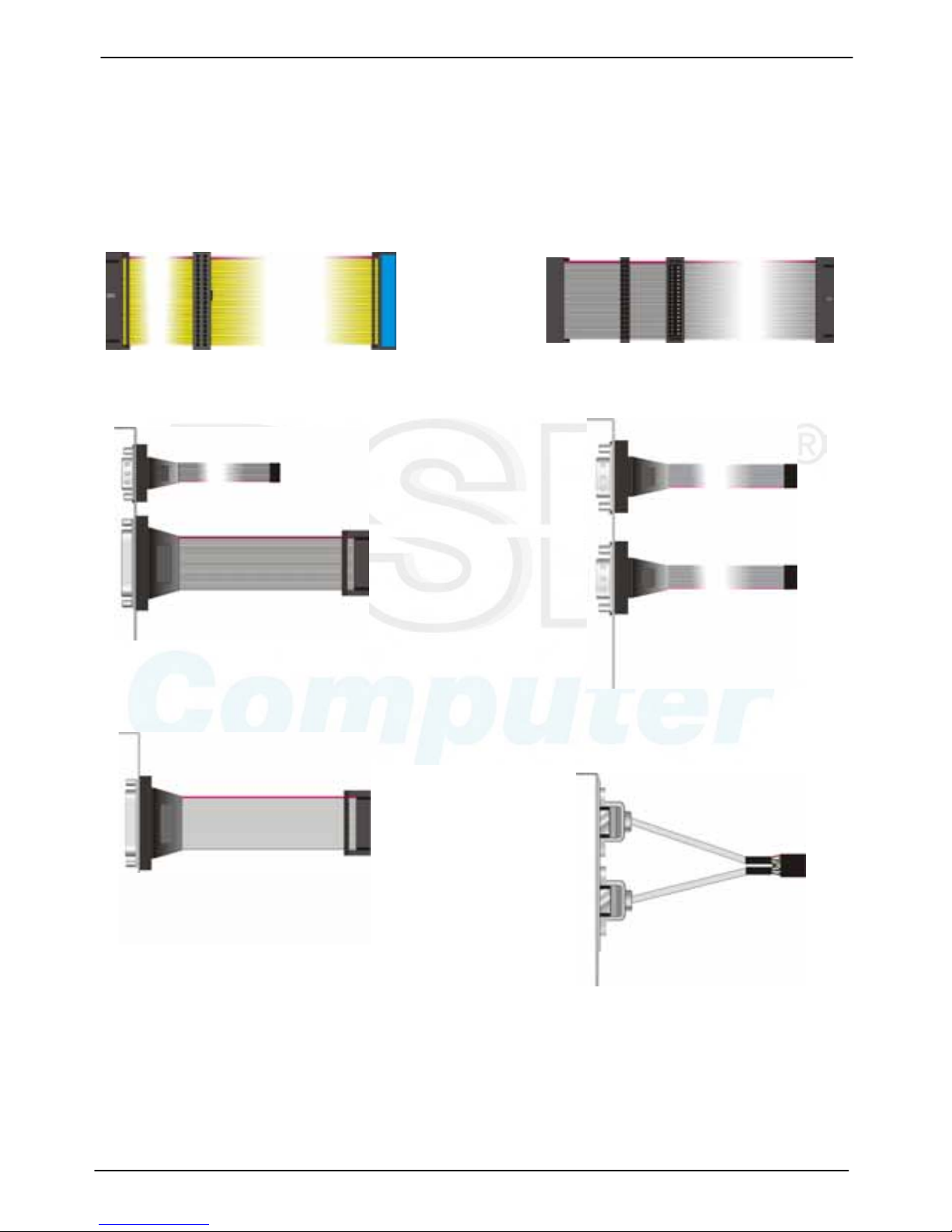
Cable Kit :
40-pin ATA 100 IDE flat cable x 2
Floppy f lat cable x 1
DB25 & DB9 cable wi th br acket x 1
Dual DB9 cable with bracket x 1
DB25 cable wit
h
bracket x 1
Dual USB cable with bracket x 2
Packing List
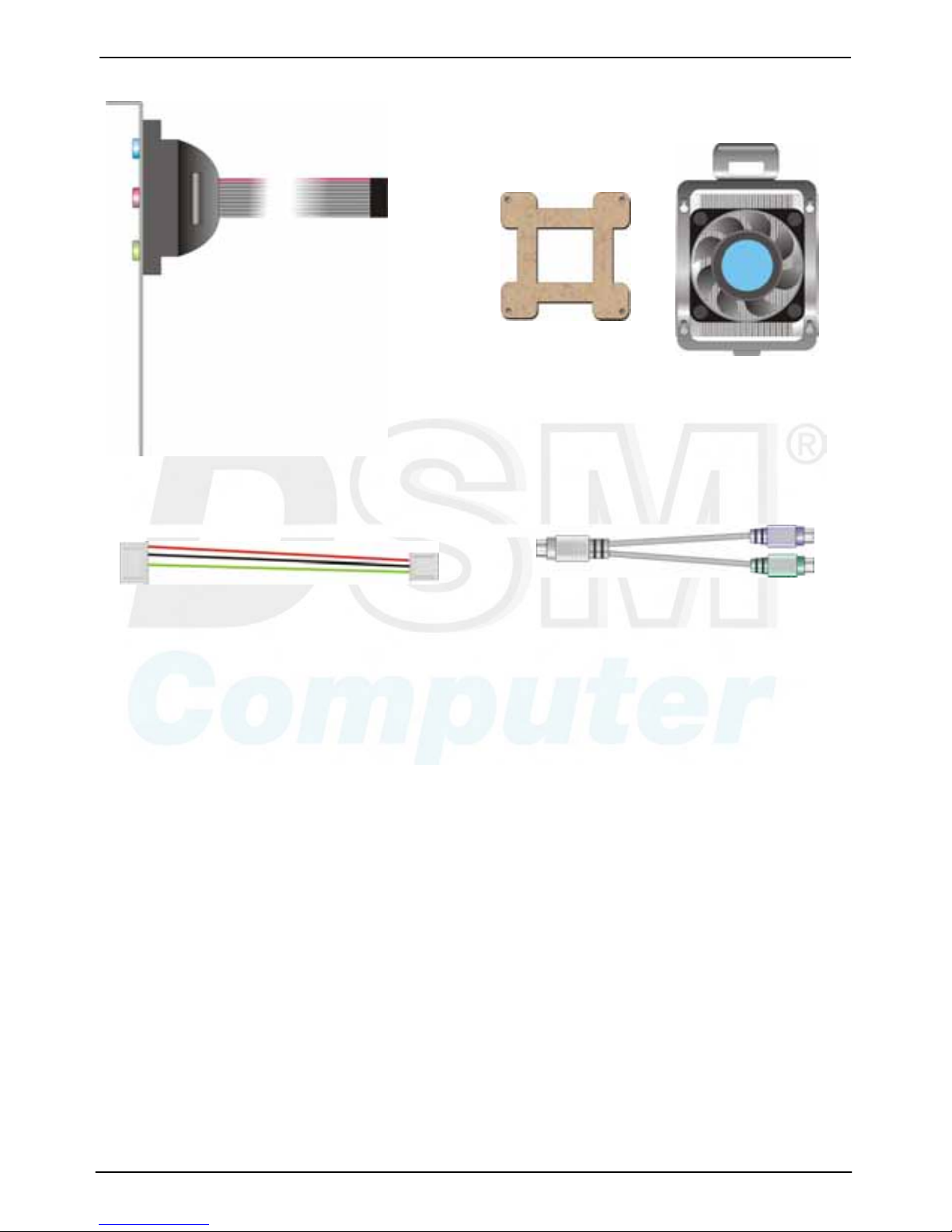
Audio cabl e wit h bracket x 1
4-pin t o 3- pin ATX cable x 1
PS/2 Keyboard & Mouse Cable x 1
Other Accessories:
Divers CD (including User’s Manual)
CPU Co o ler x 1

Index
Index
Chapter 1 < Intr oduct ions>.............................................................................7
1.1 <Product Overview>..........................................................................7
1.2 <Product Specifications>....................................................................8
1.3 <Component Placement>................................................................. 10
1.4 <Block Diagram>............................................................................. 11
Chapter 2 <Hardware Setup>.......................................................................13
2.1 <Connectors Location>.................................................................... 13
2.2 <Jumper Referenc e>.......................................................................14
2.3 <Connectors Reference> ................................................................. 15
2.3.1 <Internal Connectors>........................................................... 15
2.3. 2 < External Co nnect or s > .......................................................... 15
2.4 <System Setup>.............................................................................. 16
2.4.1 <CPU Installation>................................................................16
2.4.2 <Memory Module Installation>...............................................17
2.4.3 <CPU Cooler Installation>.....................................................18
2.4.4 <Complete the system installation>........................................19
2.5 <CMOS Setup>............................................................................... 20
2.6 <Watchdog Timer Setti ng> ...............................................................21
2.7 <Embedded Solid State Disk> .......................................................... 22
2.8 <Power and Fan Setup> ..................................................................23
2.9 <Display Interface>.......................................................................... 24
2.9.1 <Analog VGA interface>........................................................ 24
2.9.2 <Digital VGA interface>.........................................................25
2.10 <Ethernet Network Interface>.........................................................29
2.11 <Audio Interface>...........................................................................30
2.12 <GPIO interface>...........................................................................31
2.13 <Switch and Indicator>................................................................... 32

Index
Chapter 3 <Display Mode Setup> ................................................................ 33
Chapter 4 <BIOS Setup>..............................................................................37
Appendix A <I/O ports pin assignment>...................................................... 39
A.1 <IDE Port>......................................................................................39
A.2 <Floppy Port > .................................................................................40
A.3 <Parallel Port>................................................................................41
A.4 <Serial Port>...................................................................................42
A.4.1 <External DB9 COM>...........................................................42
A.4.2 <Internal COM2>..................................................................42
A.5 <USB Port>....................................................................................43
A.6 <IrDA Port>.....................................................................................43
A.7 <VGA Port>.................................................................................... 44
A.8 <LAN Port>..................................................................................... 45
A.8.1 <Gigabit Et her net Controller> ................................................ 45
A.8.2 <Ethernet Controller>............................................................45
A.9 <AT Keyboard Port>........................................................................46
A.10 <PS/2 Keyboar d & M ouse Port>..................................................... 46
Appendix B <Flash BIOS>........................................................................... 47
B.1 BIOS Auto Flash Tool ................................................................ 47
B.2 Flash Method............................................................................47
Appendix C <Watchdog Timer Programming Gui de>.................................. 49

96M4211o User's Manual Introduction
Product Overview 7
Chapter 1 <Introductions>
1.1 < Product Overview>
The 96M4211o is an all-in-one single board co mputer with P ICMG interface. Based on
Intel Mobile solutions with 855GME chipset, it supports Intel Pentium M processor
with socket479, DDR 200/266/333 SDRAM up to 2GB of capacity, Intel Extreme
Graphics 2 Technology of onboard VGA display interface, AC97 2 channel audio,
USB2.0 interface and one Gigabit Ethernet controller.
To be a powerful multimedia platform, 96M4211o is also integrated with 24-bit dual
channel LVDS interface and one Compact Flash Type II socket. For these features
96M4211o can be easily used for industrial multimedia platform like POS or KIOSK system.
Powerful Embe dded Syst em
96M4211o also supports Intel Pentium M FC-BGA2 for embedded, you can choose it for
lower voltage and power consumption, further more, and it can be done for fan free system.
With one compact flash type II socket, you can port embedded operating system like
windows CE.net or Linux Embedded for it.
Hi-Speed USB 2.0 Interface
Intel ICH4 built-in Hi-Speed USB 2.0 controller let 96M4211o offering up to 480Mbps
of Hi-Speed USB 2.0 interfaces.
96M4211o User’s Manual Introduction
Product Specifications 8
1.2 <Product Specifications>
General Specification
Form Factor Full-size PICMG CPU card
CPU Intel Pentium M Processor with FC-PGA478/FC-BGA479
Battery Mode is not supported
Intel Speed Step Technology function is not supported
Memory 2GBytes DDR200/266/333 SDRAM on one 184-pin DIMM socket
ECC is supported
Chipset Intel 82855GME GMCH and 82801DB ICH4
BIOS Phoenix-Award v6.00PG 4Mb PnP flash BIOS
Green Function Power saving mode includes doze, standby and suspend modes.
ACPI version 1.0 and APM version 1.2 compliant
Watchdog Timer System reset programmable watchdog timer with 1 ~ 255
sec./min. of timeout value
Real Time Clock Intel ICH4 built-in RTC with lithium battery
Enhanced IDE PCI enhanced IDE interface supports dual channels and up to 4
ATAPI devices at UltraATA/100
Two 40-pin IDE ports
DiskOnModule (DOM) embedded flash disk up to 1GBytes
Multi-I/O Port
Chipset Intel 82801DB ICH4 and Winbond W83627HF-AW LPC Super I/O
controller
Serial Port Two internal RS-232 serial port with 16C550 compatible UART
and 16 bytes FIFO
USB Port Four Hi-Speed USB 2.0 ports with 480 Mbps of transfer rate
Parallel Port One internal bi-direction parallel port with SPP/ECP/EPP mode
Floppy Port One FDD port supports up to two FDD
IrDA Port One IrDA compliant Infrared interface supports SIR
K/B & Mouse External PS/2 keyboard and mouse ports on rear I/O panel
One internal AT keyboard port
GPIO One 12-pin Digital I/O connector with 8-bit programmable I/O
interface
VGA Display Interface
Chipset Intel 855GME GMCH built-in Intel Extreme Graphics 2
With 266 MHz VGA core and 256-bit 3D engine
Memory Intel dynamic video memory up to 64Mbytes shared with system
Display Type CRT, LCD monitor and analog display
Connector External DB15 female connector on rear I/O panel
Internal 40-pin LVDS connector

96M4211o User’s Manual Introduction
Product Specifications 9
Ethernet Interface
Chipset Intel PRO/100+ LAN interface with Intel 82562ET
Type 10Base-T / 100Base-TX for 82562ET
auto-switching Fast Ethernet
Full duplex
IEEE802.3U compliant
Connector External RJ45 connector with LED on rear I/O panel
Audio Interface
Chipset Intel ICH4 with Realtek ALC201A AC97 3D audio codec
Interface 2 channel 3D audio with Line-in, Line-out and MIC-in
Connector Internal 10-pin header for line-in/-out, MIC-out, 4-pin header for
CD-in
Extended Interface
Type Onboard 144-pin Mini-AGP interface
Bus type 4x AGP bus
Solid State Disk Interface
Flash Type Compact Flash Type-I/II for CFC (Compact Flash Card) or IBM
MicroDrive
Capacity Up to 1GB flash memory
Power and Environment
Power
Requirement
4-pin onboard +5V/+12V power connector
ATX function Onboard 3-pin PS-ON & 5V standby connector
Dimension 338 (L) x 122 (H) mm
Temperature Operating within 0 ~ 60oC (32 ~ 140oF)
Storage within -20 ~ 85
o
C (-4 ~ 185oF)
Ordering Code
96M4211o Full-size PICMG single board computer with Intel Socket 479
Pentium-M processor Motherboard with Intel onboard VGA, LAN,
Audio, Hi-Speed USB 2.0, Compact Flash socket and LVDS
interface.
For further product information please visit our website at http://www.DSM.AG
96M4211o User’s Manual Introduction
Component Placement 10
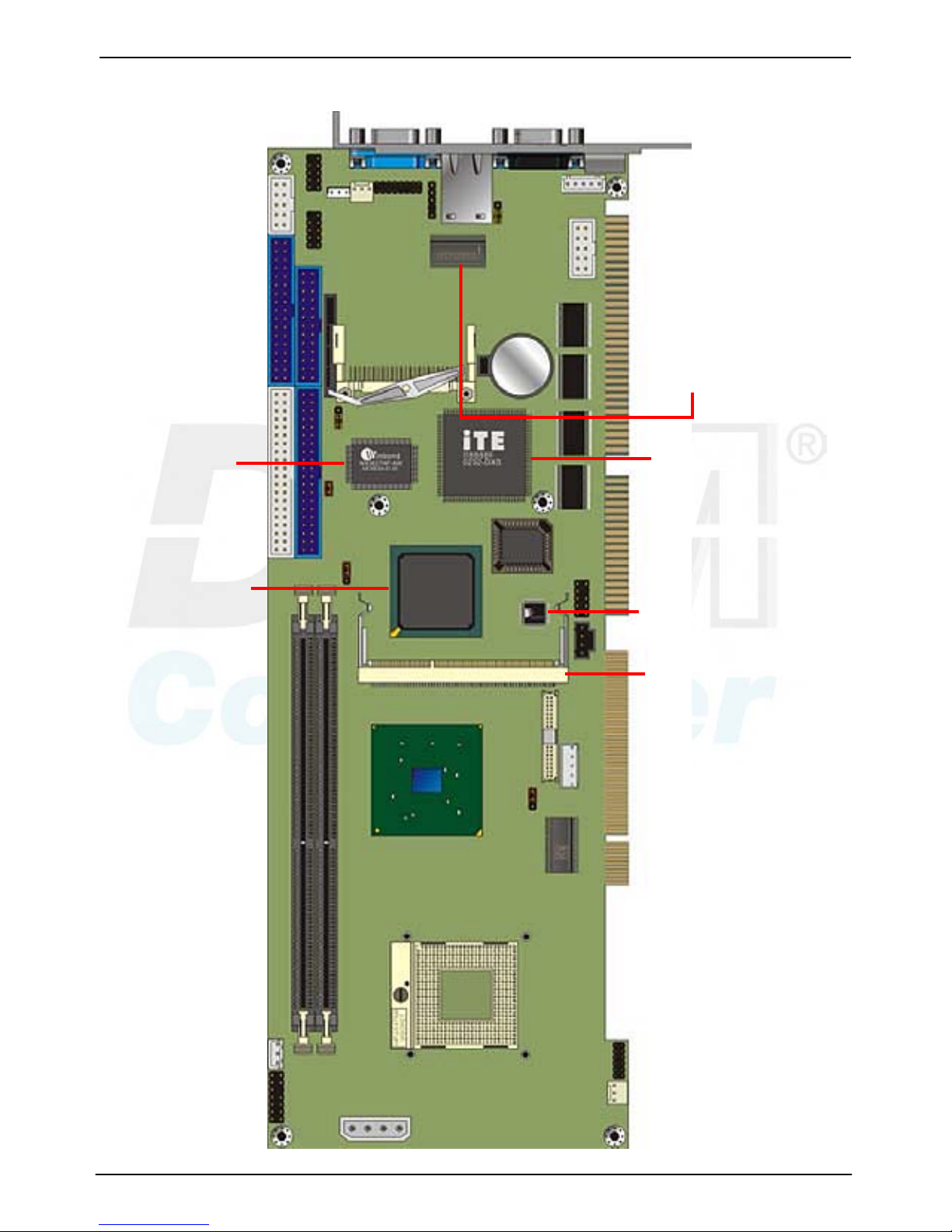
1.3 <Component Placement>
Intel Pent i um M Processor
at 400MHz FSB
2 x DDR266/333 DIM M
up to 2GB
ICH4
Intel 855GME
BIOS
Compact Flash Socket
Audio Codec
ISA Bridge
Mini-AGP
Intel 82562ET
LAN
Super I/O
96M4211o User’s Manual Introduction
Block Diagram
11
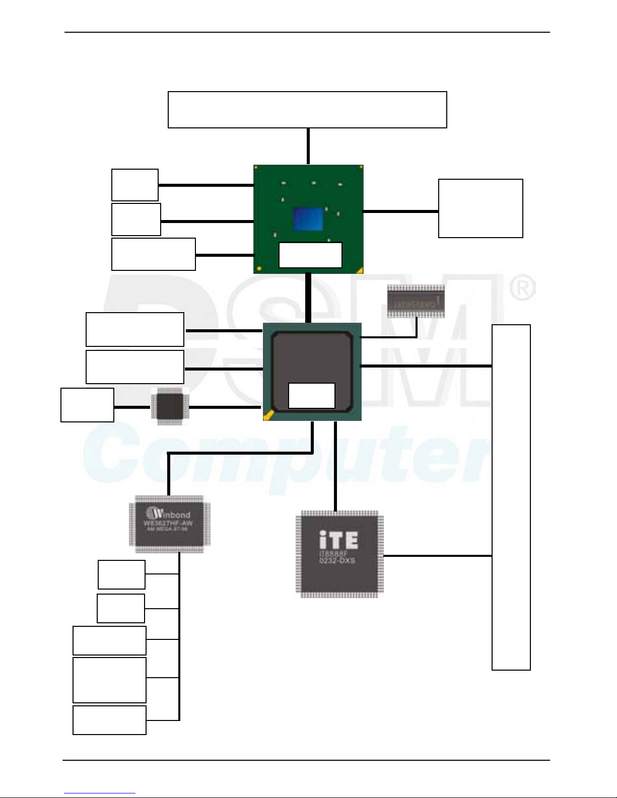
1.4 < Block Diagram>
Intel Pent i um M processor wit h FC-PGA2/FC-BG A 2
855GME
CRT
LCD
LVDS
400MHz FSB
2 x 184-pin
DIMM
Up to 2GB
DDR266/333
ICH4
AT API Devices
USB Devices
UltraATA100
USB2.0
Audio
AC97 Codec
PICMG Backplane
PCI Bus
LPC
IrDA
PS/2
COM Por t
Parallel
Port
Floppy
ISA Bus
Mini-AGP
LVDS
4xAGP
PHY
82562ET LAN

96M4211o User’s Manual
12
(Thi s page i s le f t for bl a nk)
(Thi s page i s le f t for bl a nk)
96M4211o User’s Manual Hardware Setup
Connectors Location
13
Chapter 2 <Hardware Setup>
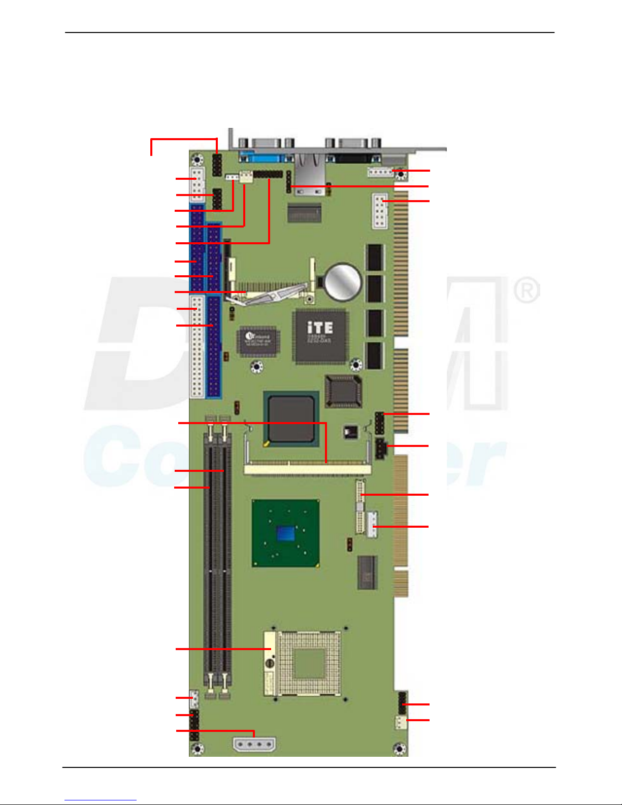
2.1 < Connectors Locatio n>
VGA RJ45 PS/2
CN_USB2
CN_COM2
CN_USB1
CN_WOL
SYSFAN
CN_VGA
FDD
CN_LPT
CF
IDE2
IDE1
MINI_AGP
DIMM1
DIMM2
CPU
CN_PS
JFRNT
CN_PWR
CN_ATKB
CN_IR
CN_COM1
CN_AUDIO
CDIN
CN_LVDS
CN_INV
CN_DIO
CPUFAN
96M4211o User’s Manual Hardware Setup
Jumper Reference 14
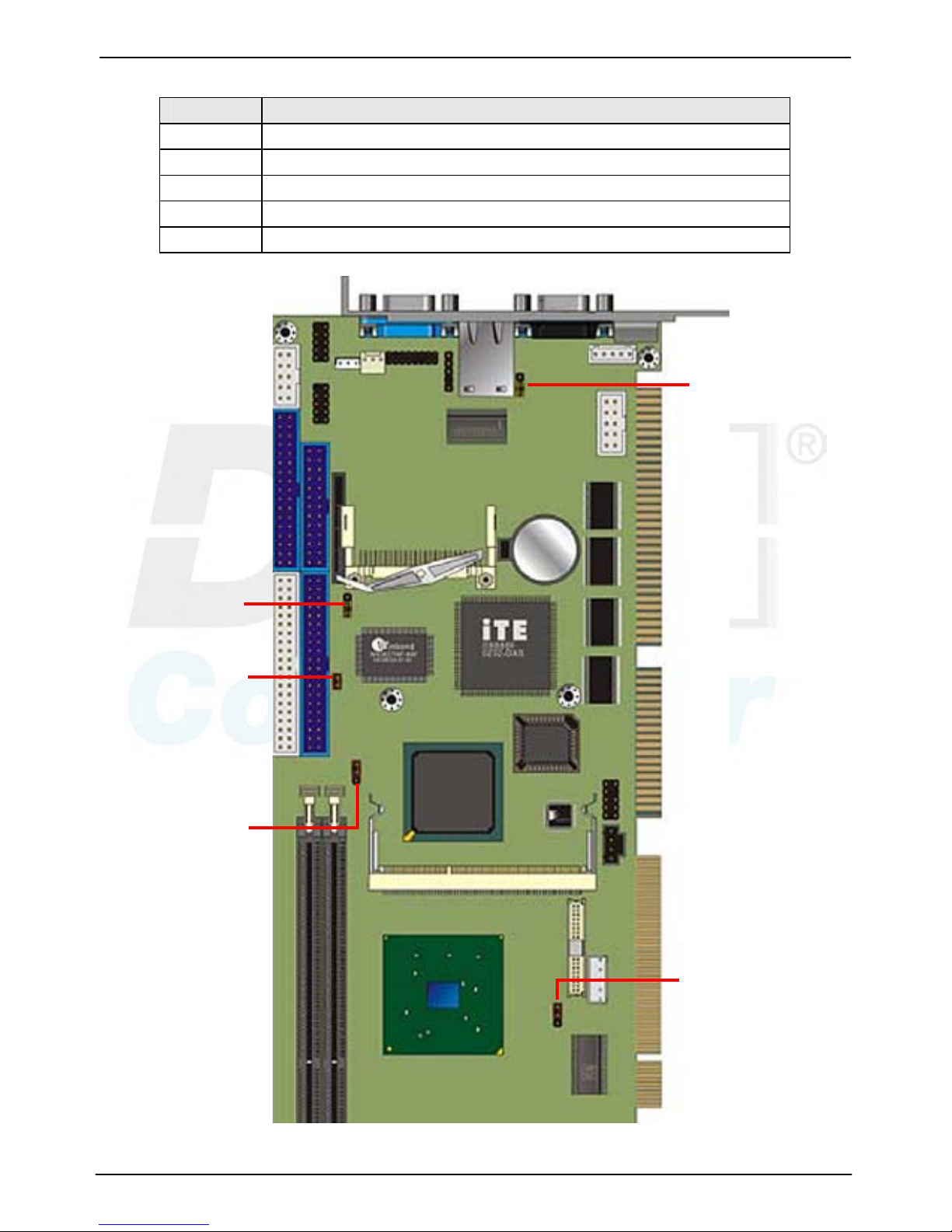
2.2 < Jumper Ref erence>
Jumper Function
JRTC CMOS Operating/Clear Setting
JCFSEL Compact Flash Addressing Setting
JDOM IDE1 Pin-20 voltage setting
JVLCD LCD Panel Voltage Setting
JLAN Ethernet Controller Enable/Disable Setting
JLAN
JVLCD
JCFSEL
JDOM
JRTC
96M4211o User’s Manual Hardware Setup
Connectors Reference
15
2.3 < Connectors Referen ce>
2.3. 1 < Inter nal Connector s>
Connector Function Remark
CPU mPGA479 CPU socket Standard
DIMM1/2 184 -pin DDR SDRAM DIMM socket Standard
IDE1 40-pin primary IDE connector Standard
IDE2 44-pin secondary IDE connector Standard
FDD 34-pin floppy connector Standard
CN_VGA 8 x 2-pin VGA connector (pitch = 2.0mm) Standard
CN_USB1/2 5 x 2-pin USB connector (pitch =2.54mm) Standard
CN_COM1/2 5 x 2-pin serial port connector Standard
CN_LVDS 20 x 2-pin LVDS connector Standard
CN_INV 5-pin panel inverter connector Standard
CN_PS 3-pin ATX function connector Standard
CN_PWR 4-pin power input connector Standard
CN_AUDIO 5 x 2-pin audio connector Standard
CDIN 4-pin CD-ROM audio input connector Standard
CN_DIO 6 x 2-pin digital I/O connector Standard
CN_WOL 3-pin wake-on-LAN connector Standard
CPUFAN 3-pin CPU fan connector Standard
SYSFAN 3-pin system fan connector Standard
CN_LPT 26-pin parallel port connector Standard
CF Compact Flash Type II socket Standard
2.3. 2 < Ext ernal Connector s>
Connector Function Remark
VGA DB15 VGA connector Standard
RJ45 RJ45 LAN connector Standard
COM1 Serial port connector Standard
PS2 PS/2 Keyboard/Mouse connector Standard
96M4211o User’s Manual Hardware Setup
CPU installation 16
2.4 < S yst em S et up>
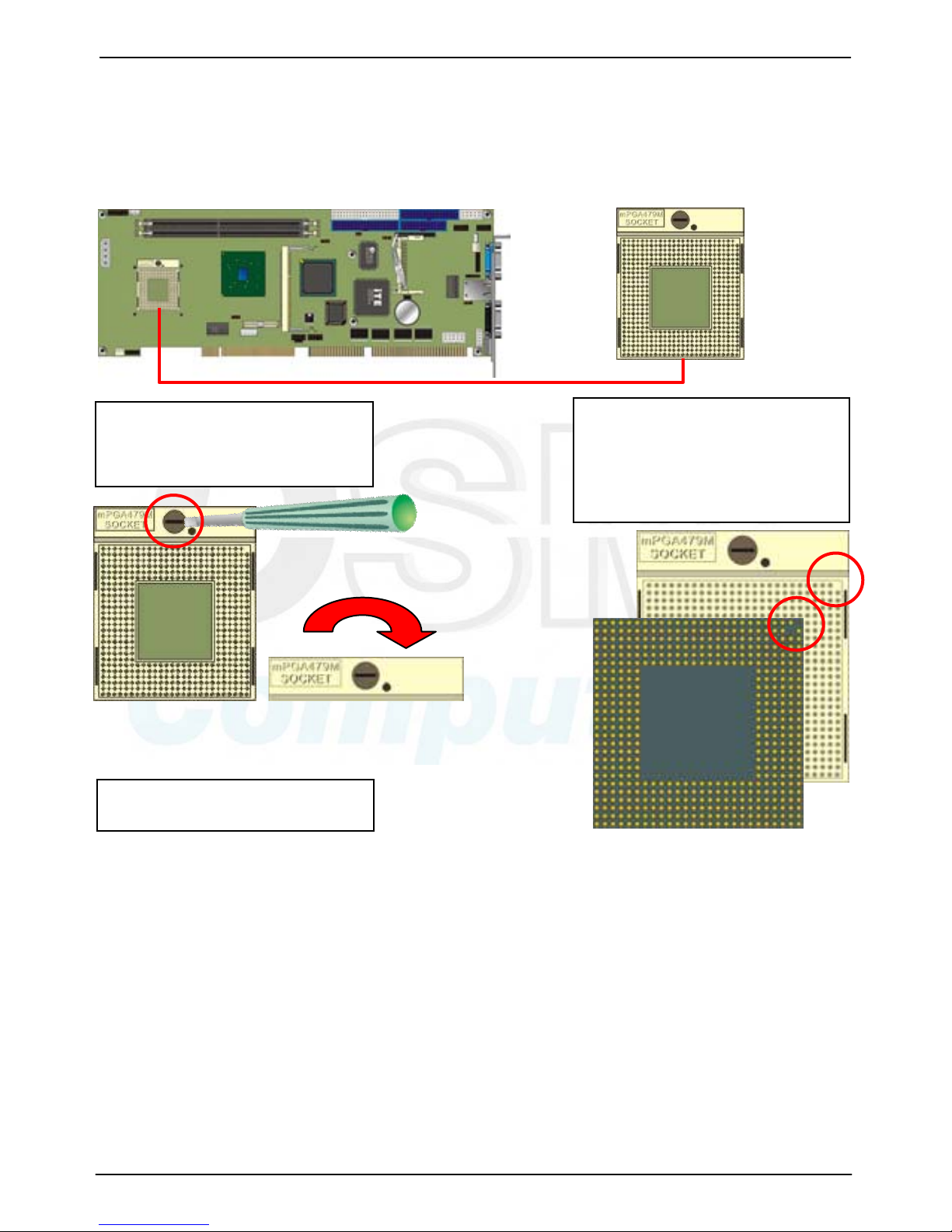
2.4. 1 < CPU Installatio n>
96M4211o has one 479-pin CPU socket to support Intel Pentium M 478-pin processor.
Please follow the instruction to install the processor well.
CPU S o cket
1. Use flat-type Screw Driver to
unlock the CPU locket
2. Find the pin di r ec tion a nd
instal l the processor on the
socket.
Unlock
3. Lock the socket well.
 Loading...