

DSI
JET User Guide
Data Sciences International
Bluetooth®
Receiver
Data Sciences International
119 14th Street NW, Suite 100
St. Paul, MN 55112
Phone: +1 (651) 481-7400
US: +1 (800) 262-9687
Email: support@datasci.com
www.datasci.com

Data Sciences International
119 14th Street NW, Suite 100
St. Paul, MN 55112
Phone: +1 (651) 481-7400
US: +1 (800) 262-9687
Email: support@datasci.com
www.datasci.com
Copyright 1997-2012 Data Sciences International. All rights reserved. No part of this manual may be reproduced,
translated, transcribed, or transmitted in any form or by any means manual, electronic, electromagnetic, chemical, or
optical without the written permission of Data Sciences International.

DSI JET User Guide Contents • iii
Contents
Notices 1
FCC Notice ................................................................................................................................ 1
Industry Canada Notice ............................................................................................................. 1
EU Notice – Declaration of Conformity .................................................................................... 1
Battery Information ................................................................................................................... 2
Disclaimer .................................................................................................................................. 2
Product Warranty ....................................................................................................................... 2
Product Repairs .......................................................................................................................... 2
Verification ................................................................................................................................ 2
About This User Guide 3
Related Documentation.............................................................................................................. 3
Theory of Operation 4
Specifications 6
JET Device Models .................................................................................................................... 6
JET Bluetooth® Receiver .......................................................................................................... 6
General Specifications ............................................................................................................... 6
JET Device –Technical Specifications......................................................................... 6
Mechanical Specifications for JET Device .................................................................. 7
JET Device Battery Specifications .............................................................................. 7
General Specifications for JET Receiver ..................................................................... 7
Mechanical Specifications for JET Bluetooth® Receiver ........................................... 8
Lead Sets .................................................................................................................................... 9
Monitoring ECG with JET and a 3 Channel ECG Lead Set .................................................... 10
Monitoring ECG or other Bio-potentials with JET and a Differential Lead Set ...................... 11
To Instrument a Dog for Measurement 11
Supplies Needed ...................................................................................................................... 11
Jacket Pocket Size Recommendations ..................................................................................... 12
To Attach the Electrodes.......................................................................................................... 13
To Install the JET Device and Connect the ECG Leads .......................................................... 14
Use of JET Blood Pressure Add-On ........................................................................................ 14
To Place Respiratory Inductive Plethysmography (RIP) Bands .............................................. 15
Attaching Leads to Band Sensors ............................................................................................ 15
Cleaning the Sensors ................................................................................................................ 16
Technical Specification............................................................................................................ 17
To De-instrument a Dog 17
Maintenance 17

iv • Contents DSI JET User Guide
To Charge the Battery .............................................................................................................. 17
To Clean the JET device and Leads ......................................................................................... 19
Room Setup Recommendations 20
Purpose .................................................................................................................................... 20
JET Bluetooth Receiver Location Recommendations ............................................................. 20
Required Utilities ..................................................................................................................... 20
Networking .............................................................................................................................. 21
Overall System Integrity ................................ ................................................................ .......... 21
JET Bluetooth Receiver Protection Recommendations ........................................................... 21
An example installation ........................................................................................................... 21
Troubleshooting 22
Technical Support 24
Appendices 25

DSI JET User Guide Notices • 1
Notices
FCC Notice
The JET subject’s device contains FCC ID QOQWT12 which complies with part 15 of the FCC Rules. Operation is
subject to the following two conditions:
1. This device may not cause harmful interference, and
2. This device must accept any interference received, including interference that may cause undesired operation.
The JET Receiver 272-0241-001 contains 3 transmitter modules with FCC ID: QOQWT141, IC ID 5123A-BGTWT41.
Device 272-0241-001 compiles with Part 15 of the FCC Rules Operation is subject t the following two conditions.
1. This device may not cause harmful interference, and
2. This device must accept any interference received, including interference that may cause undesired operation.
Each 272-0241-001 should be at least 20cm separation between the receiver and all persons.
Changes or modifications not expressly approved by the party responsible for compliance could void the user's authority
to operate the equipment. Please refer to the www.datasci.com website for more information.
Industry Canada Notice
The JET subject device contains IC: 5123A-BGTWT12A which complies with RSS 210 of Industry Canada. Operation
is subject to the following two conditions: (1) this device may not cause harmful interference, and (2) this device must
accept any interference received, including interference that may cause undesired operation.
The JET Receiver 272-0241-001 contains 3 transmitter modules with FCC ID: QOQWT141, IC ID 5123A-BGTWT41
which complies with RSS 210 of Industry Canada. Operation is subject to the following two conditions: (1) this device
may not cause harmful interference, and (2) this device must accept any interference received, including interference that
may cause undesired operation.
EU Notice – Declaration of Conformity
In accordance with Annex IV of the EU directive 1999/5/EC, Data Sciences International declares under our
responsibility that the JET product complies with the appropriate essential requirements of the R&TTE Directive and the

other relevant provisions, when used for its intended purpose. Please refer to the www.datasci.com website for more
information.
Battery Information
The JET device uses a removable and rechargeable Lithium Ion battery. Replacement of this battery is recommended
every 1 to 2 years depending upon storage and use conditions.
The JET RIP Modules contain a non-removable, and non-rechargeable Lithium / Manganese Oxide battery. The battery
has sufficient capacity for greater than 2700 hours of use. To maximize useful life it is recommended that the modules
be stored individually and without any cable connections.
Consult with your federal, state/province and local laws for acceptable disposal.
Disclaimer
The JET device and accessories described in this User Manual are not intended to be used and should not be used in
human experimentation or applied to humans in any way.
Product Warranty
Each JET device is warranted for 12 months. Should the JET device fail to perform within specification during the warranty
period, it will be repaired or replaced with a new unit.
Product Repairs
Repairs to the JET Device and accessories are dependent upon the amount and type of damage that is present. For example,
repair of a device due to damaged battery tabs or a damaged lead set jack is feasible. Repair of a damaged circuit board is
not feasible. .
Verification
DSI hardware and software are extensively tested and calibrated before leaving our factory or warehouse. Researchers
should independently verify the basic accuracy of materials delivered.

About This User Guide
This User Guide provides instructions on how to set up and operate the DSI JET System. The DSI JET™ System is
designed to be used in conjunction with the Ponemah™ Physiology Platform (P3 Plus)/Life Science Suite software for
data acquisition and analysis.
Related Documentation
Please refer to the manual for the Ponemah Physiology Platform (P3 Plus)/Life Science Suite for instructions on how to
configure and use the Ponemah software applications.
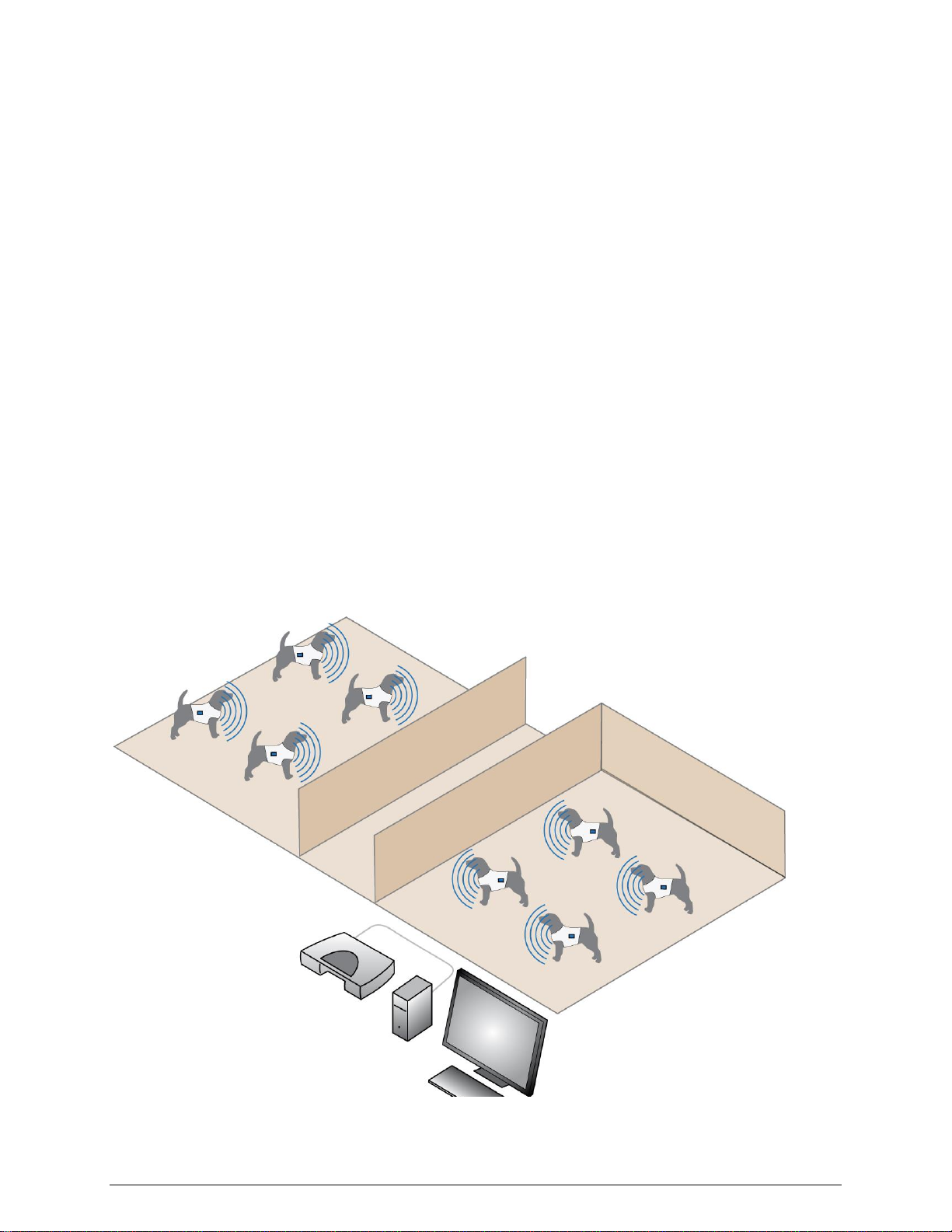
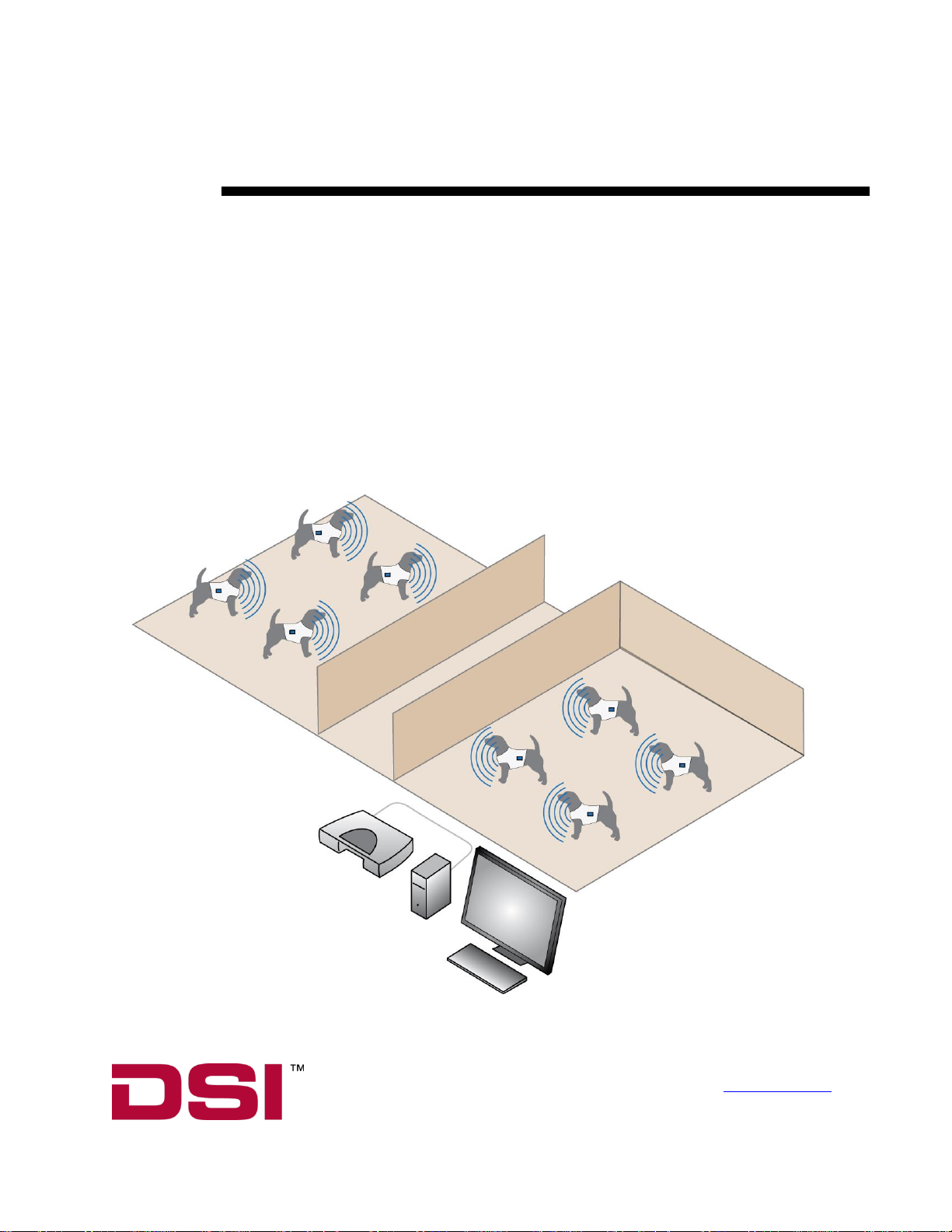
Theory of Operation
Refer to Figure 1 below.
The JET™ System consists of externally worn telemetry devices. JET is a Bluetooth
®
enabled system specially
designed for toxicology and safety pharmacology laboratories running large animal studies. It can be used to
monitor ECG, temperature, and activity. Accessories may be used in tandem with the JET device to collect
additional endpoint (e.g. respiration and blood pressure) as described later in this document.
The use of the Bluetooth technology allows for group housing and a large number of animals per animal room.
In a JET System, surface electrodes are placed on an animal and are connected to a JET device. The JET device is
then placed into a pocket of an externally worn animal jacket. The JET device transmits to a Bluetooth® receiver.
Each Bluetooth® receiver can receive signals from up to 6 JET devices depending upon the device type. Each JET
device can transmit data up to 10 meters with negligible interference and no cross-talk exists between animals.
Bluetooth®
Receiver
Figure 1 JET System in Group Housing Configuration Figure 1 JET System in Group Housing Configuration
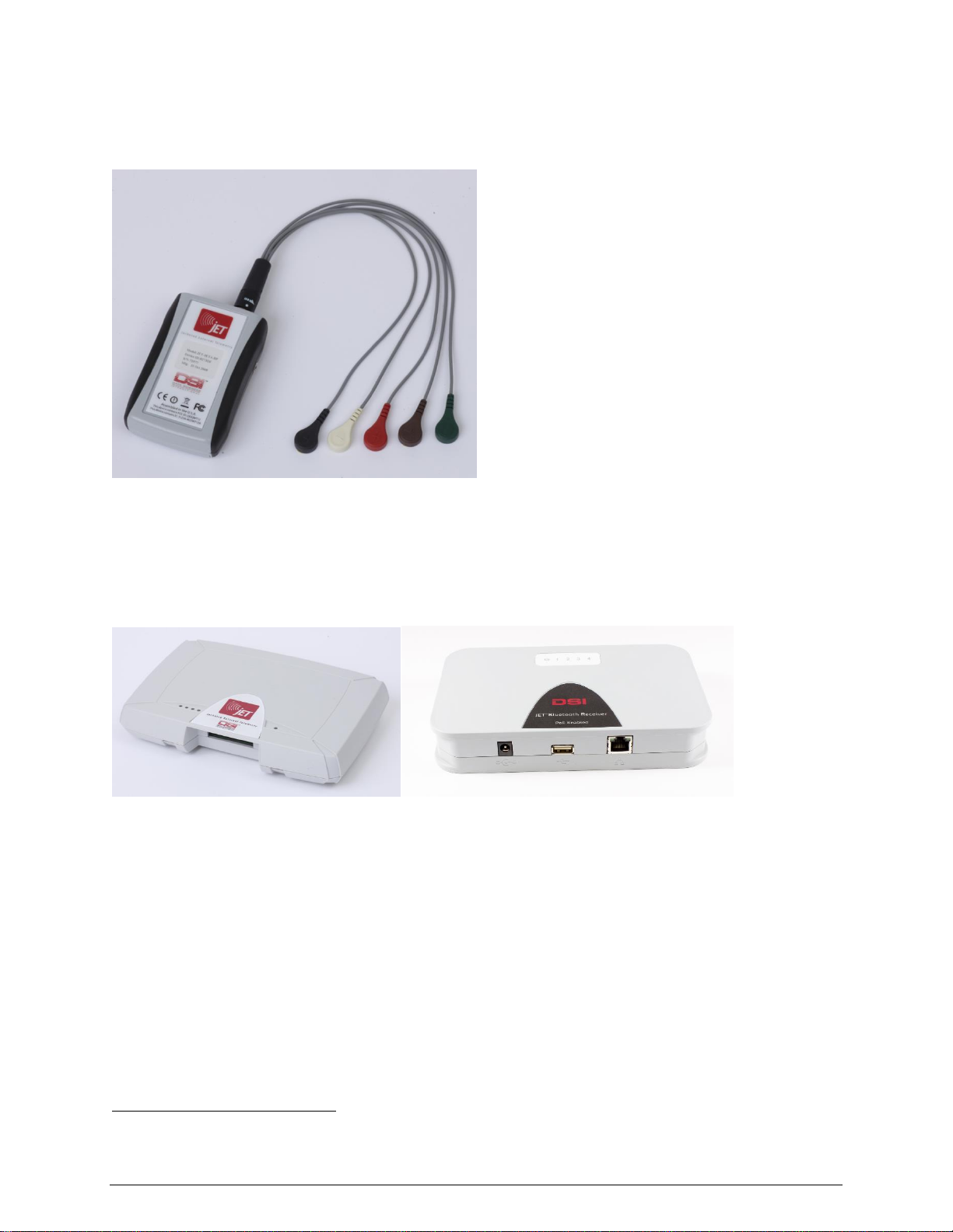
There are 3 models of JET devices available. The models differ by the number of channels that can be recorded by
each device. The housing of each of the 3 models is the same, with the devices differentiated based on the lead set
that is connected.
Figure 2 JET-3ETA-BP Device
The Bluetooth Receiver can accommodate up to six JET-EA-BP, four to six1 JET-3ETA-BP or four JET-5ETA-BP
devices. The receiver needs to be placed in the animal room, but does not need to be in an animal cage. Multiple
receivers can be used in the same room to record from a total of 36 JET devices per room via multiple systems.
(The device limit per room for JET-5ETA-BP devices is 18.)
Figure 3 JET Bluetooth Receivers Model 2293 (left) and 272-0241-001 (right)
The JET system functions with the industry-leading Ponemah software. The Ponemah system provides continuous
data storage and experimental analysis either as they occur, or during subsequent review, with the option of
performing these actions within GLP guidelines. This solution is designed for the researcher whose protocol
demands flexibility with accurate, continuous and multi-channel acquisition and analysis in a validated environment.
The Ponemah system is modular, allowing users to custom design the configuration based upon their application,
budget and convenience — without any programming. Each Ponemah system allows up to 16 individual JET
devices to be recorded at one time though there is also a limitation of 128 channels. Through the use of multiple
Ponemah systems and multiple JET Bluetooth receives it is possible to monitor 36 animals in a single animal room
using JET-EA-BP or JET-3ETA-BP devices or 18 per room using JET-5ETA-BP devices.
1
For a small number of devices, 6 devices per receiver may be acceptable. 4 devices per receiver are recommended for optimum performance.

Specifications
JET Device Models
Refer to Figure 2.
There are 3 different models of JET devices. The main differentiator between each of the devices is the number of
channels per device. The JET-5ETA-BP device includes a second jack enabling a 2nd lead set to be connected (not
pictured).
JET-EA-BP
JET-3ETA-BP
JET-5ETA-BP
Number of ECG leads
available per device*
1 7 9
Number of BP capable
channels available per
device**
1 1 1
Respiration
Capability
***
No
Yes (with 1 lead ECG)
Yes (with 7 lead ECG)
Activity
3-axis accelerometer
3-axis accelerometer
3-axis accelerometer
Temperature
No
Surface Thermistor
Surface Thermistor
*
Some of the ECG channels are derived by the Ponemah P3 software.
**
A JET BP Add-On is required to use this functionality.
***
A JET RIP Add-On is required to use this functionality.
JET Bluetooth® Receiver
Refer to Figure 3.
The JET Bluetooth® receiver transfers data from individual JET devices to the data acquisition and analysis
software. The receiver can receive signals from up to six JET-EA-BP’s, four to six2 JET-3ETA-BP’s or four JET5ETA-BP’s devices at one time.
Ponemah supports both the older JET Receiver (2293) and the new JET Receiver (272-0241-001) on the same
system at the same time.
General Specifications
The table below identifies the major specifications for the components of the JET System.
JET Device –Technical Specifications
Biopotential
Temperature
Activity
Input Range: ± 10 mV
Input Range: 0 to 70 deg. C.
Three-axis accelerometer
Sample Rate: 750 Hz
Sample Rate: 10Hz
Sample Rate: 50 Hz
Bandwidth: 0.1 to 250 Hz
Accuracy: 0.5 deg. C.
Input Impedance: > 10 M
Noise: <20 V peak-to-peak
Resolution: 16 bits
2
For a small number of devices, 6 devices per receiver may be acceptable. 4 devices per receiver are recommended for optimum performance.
Blood Pressure Add-On
Respiratory Add-On
equivalent to implant
Sample Rate: 50Hz
Resolution: 16 bits
Rate Accuracy: 5% or 2 breaths per minute
Measurement Range: 0–150 breaths per minute
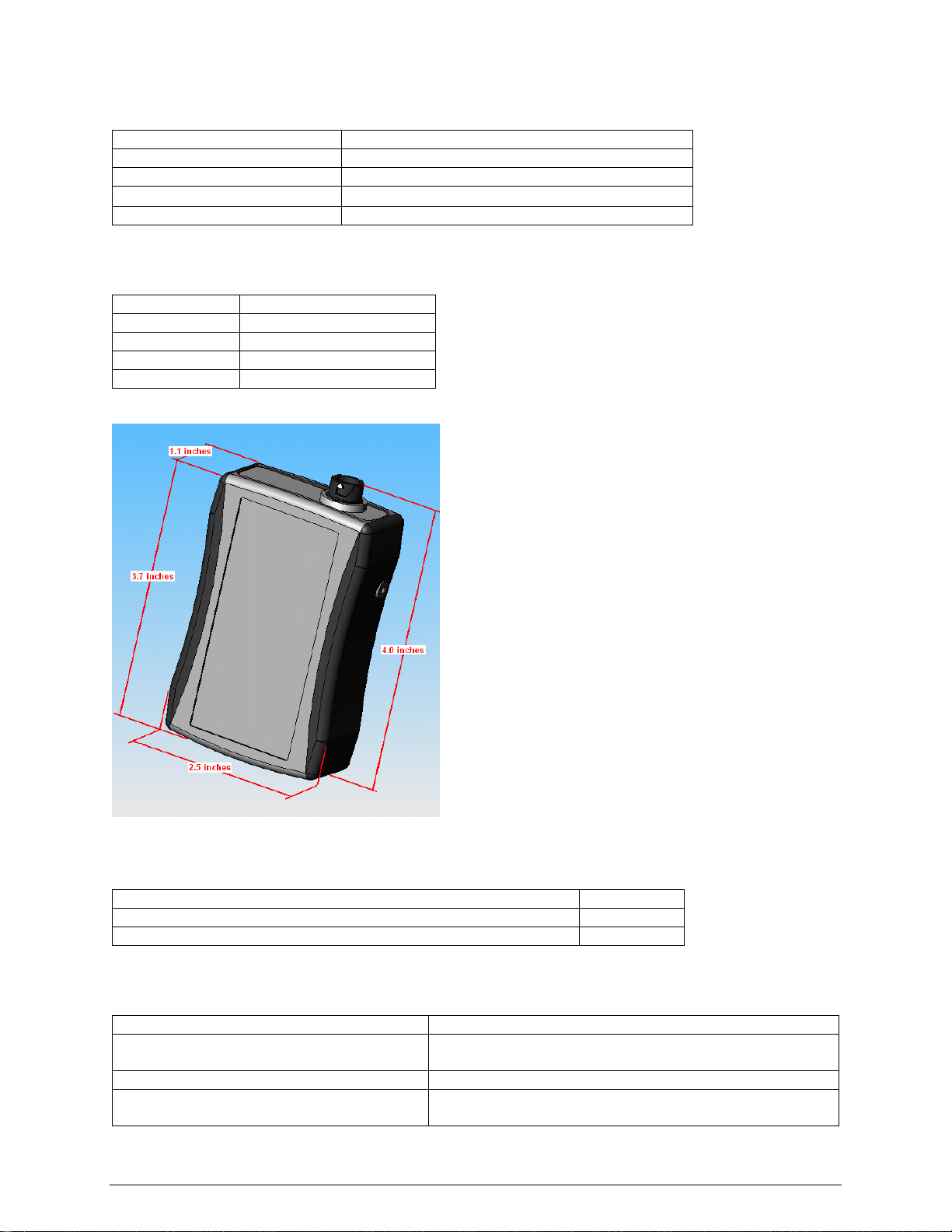
Mechanical Specifications for JET Device
Length
2.5 Inches (6.35 cm)
Width
1.1 Inches (2.8 cm)
Height
3.7 inches (9.45 cm)
Total Volume
168 CCs
Weight
150 grams
Note that dimensions do not include the lead sets. The lead sets will add about 15 CCs to the total volume.
Figure 4 Dimensions of JET Device
JET Device Battery Specifications
Type
Lithium Ion
Transmission time (from full charge without BP Add-On in use)
27 hours
Transmission time (from full charge with BP Add-On in use)
25 hours
Note: See appendix for detail on care and use of these batteries over time.
General Specifications for JET Receiver
Animals Per Ponemah (P3) system
Up to 16
Transmission range between device and
receiver
10 meters
Number of JET devices per receiver
Up to 6 (dependant on device type)
Receiver connection to P3 system
Receiver can be connected directly to computer via an
Ethernet cable through a network card or into a local area
network. For more details on receiver connection to the
system, please refer to the PONEMAH Physiology Platform
user guide.
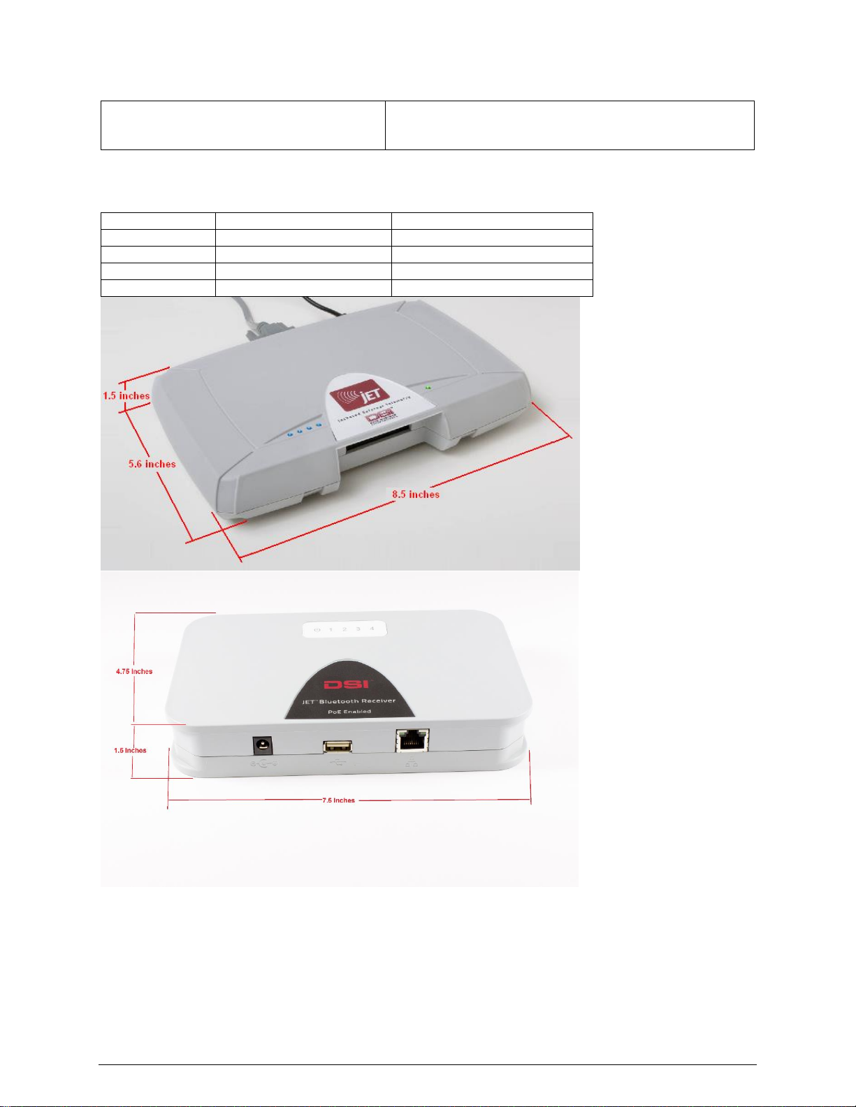
Mechanical Specifications for JET Bluetooth® Receiver
JET Receiver 2293
JET Receiver 272-0241-001
Length
8.5 inches (21.6 cm)
7.5 inches (19.1 cm)
Width
5.6 Inches (14.2 cm)
4.75 inches(12.1 cm)
Height
1.5 Inches (3.8 cm)
1.5 inches (3.8 cm)
Weight
450 grams
Figure 5 JET Bluetooth Receivers with dimensions

Lead Sets
Figure 6 Lead Set for collecting 7 leads of ECG

There are 3 different lead sets available for each of the JET devices. Each type of lead is available in versions that
are approximately 12 or 26 inches long.
A
1 channel
differential lead
set
Consists of a pair of differential leads (positive, negative) and a
reference lead.
B
3 channel
differential lead
set
Consists of 3 pairs of differential leads (positive, negative) and a
reference lead
C
3 channel ECG
Lead Set
Consists of 3 leads that share a common negative and a separate
reference lead (shown in figure 6 above)
The following table identifies the compatible lead set for each of the JET models.
JET Model
Lead sets used by the device
JET-EA-BP
A
JET-3ETA-BP
B or C
JET-5ETA-BP
Needs 2 lead sets, can be any combination of B or C
Monitoring ECG with JET and a 3 Channel ECG Lead
Set
The primary use of the JET system is to monitor ECG. The JET devices use standard ECG skin electrodes. The
color coding for the provided 3 Channel ECG lead set is based on the Association for the Advancement of Medical
Instrumentation (AAMI) standards. The following table outlines where the colored leads would be placed on an
animal.
Location
AAMI (US, Japan)
Channel Reference
Left Arm (LA)
Black
Positive Input for Channel 1
Right Arm (RA)
White
Negative Input for Channels 1, 2, and 3
Left Leg (LL)
Red
Positive Input for Channel 2
Right Leg (RL)
Green
Reference Input
Chest Lead or V lead (Vx)
Brown
Positive Input for Channel 3
As previously mentioned, Leads I and II are measured directly and the rest of the ECG leads are derived by the P3
software. The calculations used to derive the other leads are shown below.
Lead I = Channel 1
Lead II = Channel 2
Lead III = Channel 2 – Channel 1
aVR= – (Channel 1 + Channel 2) / 2
aVL= Channel 1 – ((Channel 2) / 2)
aVF= Channel 2 – ((Channel 1) / 2)
Vx= Channel 3 – ((Channel 1 + Channel 2) / 3)
If a second 3 channel ECG lead set is used, 2 additional V leads may be calculated by the software using the
calculations below.
Vx2= Channel 5 – ((Channel 1 + Channel 2) / 3)
Vx3= Channel 6 – ((Channel 1 + Channel 2) / 3)
Care must be taken so as to not to mix up the Channel 1-3 and Channel 5-6 lead sets or the animal wiring will be
incorrect until the plugs are switched. Channel 4 is dedicated to the Blood Pressure jack.

Monitoring ECG or other Bio-potentials with JET and a
Differential Lead Set
Wire the animal using the positive and negative leads as needed to obtain the desired leads with no calculations or
derivations within the software.
To Instrument a Dog for
Measurement
Please Note: This user guide is not meant to function as a guide to animal care or handling. Appropriate animal
handling and care measures must be determined by the laboratory before using this device.
Supplies Needed
Item
Qty.
Comments
JET Device
1/dog
Lead Set(s)
1-2/dog
Depends on JET Model used, 2 necessary for JET-5ETA-BP
Snap Electrode Patches
3-7
Depends on lead set and JET model used.
Thermistor
1/dog
Optional
Shaving Supplies
n/a
Electric Razor, Disposable Razor, Shaving Cream, Depilatory
Misc. Supplies
n/a
Abrading Gel, Gauze Wrap
Jacket
1/dog
The jacket dimensions must be customized for your animal
The minimum jacket pocket dimensions are shown in Figure 7.
Contact your DSI Salesperson for a list of companies providing
jackets that have been optimized for use with JET devices.
Undershirt or Self
Adhesive Elastic Bandage
1/dog
A method of compressing and holding the electrodes in place and/or
holding respiratory belts in place is optional. A wrap or undershirt
can be used.
JET Respiration Add-On
1/dog
If desired, this will plug into 2 of the differential biopotential channel
inputs.
JET Blood Pressure AddOn
1/dog
If desired, this will plug directly into the JET device.

Jacket Pocket Size
Recommendations
Refer to Figure 7.
Overall Size
The pocket in which the JET Device will be contained must have
minimum dimensions of 6” (15.2 cm) long by 2.75” (7 cm) wide by
1.25” (3.2 cm) deep in order to accommodate the JET device.
Dimensions slightly larger than those shown in Figure 7 are
recommended especially if one desires to use any JET Add-Ons such as
respiration or blood pressure.
Through Hole
The center of the one-inch diameter through hole must be at least 6”
(15.2 cm) from the bottom of the pocket and at least 1.25” (3.2 cm) from
the pocket sides. This hole allows the leads to be routed inside of the
jacket for attachment to the animal.
Figure 7 Pocket Dimensions

Pocket Location on the Jacket
The recommended pocket location is either on the back or flank depending upon the animal being used. If the pocket
is located on the back, it should be located close to the tail of the animal (with the top of the pocket toward the
head). If the pocket is located on the flank, it should be located about midway between the front and rear legs.
To Attach the Electrodes
1. Prepare the electrode and thermistor location sites as follows:
a. Shave the electrode and thermistor areas. (Refer to Figure 8)
b. Treat the shaved areas with the depilatory if necessary to denude the skin.
c. Perform any additional site preparation as required (abrasion, etc.).
d. Confirm the quality of the site preparation.
2. Place the thermistor on the animal, and then tape the thermistor in place.
3. Make sure the thermistor adheres adequately to the site.
4. Attach the electrodes to the appropriate sites according to the lead color as shown in
Figures 8a or 8b if using the 3 Channel ECG lead set for 7 Lead ECG; otherwise use your own preferred
locations for the leads desired. The diagram below exhibits the lead placement necessary for 6 leads of ECG
(Lead I, II, III, aVr, aVl, and aVf). The brown lead on the ECG lead set would be used for a V-lead
measurement. The brown lead can be placed in several different locations.
Note: It’s recommended that you avoid attaching the leads to areas of active muscle movement. This will help
minimize movement artifact. Also, if using the Respiratory Add-On avoid placing electrodes where the respiratory
belts will reside.
Figure 8a Recommended ECG Lead placement (Note: V lead not shown)
Note: Black and White electrodes are on clavicles. Green and Red electrodes are on rib cage.

Figure 8b. Alternative ECG Lead placement for dogs (without Respiration)
5. Attach the leads to the electrodes.
6. Make sure the electrodes adhere adequately to their sites.
7. Route the thermistor and electrode leads to where the jacket hole will be when the jacket is on the animal.
8. Optionally wrap the animal with a thin layer of gauze followed by a thin layer of self-adhesive elastic bandage
covering the electrode leads and wires. Make sure the leads are able to be routed through the jacket hole and to
the JET device. A snug undershirt may be used in place of the gauze and wrap if available.
To Install the JET Device and Connect the ECG Leads
1. Place the jacket onto the animal. Route the thermistor and electrode leads through the jacket hole and position
the lead plugs at the jacket pocket.
2. Connect the leads and thermistor to the JET device.
3. Make sure the back side of the JET device is facing away from the animal as instructed on the unit, then place
the unit into the jacket pocket.
4. Apply additional self-adhesive elastic bandage to hold the leads in place if necessary, then close and secure the
jacket pocket.
Use of JET Blood Pressure Add-On
In order to obtain a Blood Pressure signal into the JET Device a pressure only transmitter (e.g.
PA-C10) must be implanted into a blood vessel of the test subject and turned on. In addition, a
JET BP Add-On must be plugged into the JET Device with the antenna portion placed as close
as possible and less than or equal to 5 inches from the implanted transmitter. It is
recommended that this antenna be secured in place relative to the jacket or undershirt so that
the antenna to implant positioning is maintained throughout data collection.

To Place Respiratory Inductive Plethysmography (RIP)
Bands
1. Select the proper size band for the test subject and strap around the abdomen (above the navel and below the
ribcage) and chest (just distal to the forelimbs). Refer to Figure 9. A snug undershirt may be used if available.
2. Attach the first wire to the snap that is on the same side of the band as the
Velcro patch.
3. While holding this end to the left of the test subject’s centerline, wrap the band
around the test subject’s abdomen or chest.
4. Pull the other end over the first end and secure the band on the right side of the
centerline. The band should be snug but not too tight.
5. Attach the second wire to the exposed snap.
Figure 9 Suggested RIP
Band placement for dogs
Attaching Leads to Band Sensors
Figure 10 Abdomen and Chest Electronics Modules
A variable gain pot screw is located on the side of each electronics module. Turning the gain counter-clockwise
until a click is noticed provides the minimum gain setting. Maximum gain is achieved by turning the gain clockwise.
To determine proper gain settings start with minimum gain (full counter clockwise) and increase (turn clockwise)
until minimum useable signal is observed. Typical gain settings are 1-3 turns for beagle, 3-7 turns for cynomolgus
monkey.
Note: Each RIP Module contains a battery. As such the devices have a finite life conservatively
estimated at greater than 2700 hours of continuous use. To assure battery depletion does not occur
during storage it is recommended to have the modules disconnected from anything and stored
individually in a plastic bag.
Attach the electronics module to the RIP bands as pictured in Figure 11.
Note: Prior to connecting the cables to the modules assure the connectors are free from debris (e.g. fur)
or functionality of the RIP module could be impacted.

Figure 11 Attachment of Modules to Bands
The Chest and Abdomen modules should be connected to the 3 Channel Differential Lead as pictured in Figure 12.
The Chest Module should be connected to the White snaps and the Abdomen Module should be connected to the
Red snaps. Make sure when connecting to match polarity (i.e. + to + and - to -).
Figure 12 Attachment of Modules to 3 Channel Differential Lead Set
Cleaning the Sensors
• The bands are machine washable.
• Wipe the sensor and cable with a non-corrosive (to plastic) cleanser to clean before use.
• Make sure the complete sensor assembly is thoroughly dry before reusing it.
• To sterilize the sensors / bands, use standard gas sterilization procedures.
• Do not autoclave or soak the sensor in disinfectants.

Technical Specification
JET RIP Add-On
Operating conditions:
5○C (40○F) – 40○C (104○F)
Storage temperature:
-20○C (-4○F) – 60○C (140○F)
Operating and storage humidity:
5% - 95% (Non-condensing)
To De-instrument a Dog
1. Open the jacket pocket and remove the JET device from the pocket.
2. Disconnect the thermistor and electrode leads from the JET device.
3. Carefully remove the jacket, self-adhesive elastic bandage and gauze wrap from the animal so as not to affect
the electrode/tape adhesion.
4. Remove the thermistor and electrodes and/or RIP bands from the animal.
Maintenance
To Charge the Battery
Note: The computer will display a “weak” warning when the JET device has approximately two to three hours of
battery life remaining.

Figure 13 Back of JET device shown with compartment door removed
Refer to Figure 13.
1. Slide the latch to open the battery compartment door.
2. Remove the battery from the JET device.
Figure 14 Back of JET device with battery removed
Refer to Figure 14.
3. Plug the DSI-supplied charger into a standard wall outlet, and then insert the battery into the charger bay such
that the metal plates on the battery line up with the contacts in the bay.
Note that the green LED on the charger will blink to indicate that the battery is charging.

Figure 15 Battery connected to one of the two versions of supplied chargers
Warning: Use only the DSI-supplied charger when charging the JET device battery. The
use of any other battery charger other than the charger supplied with the JET
device can pose a fire hazard.
4. When the battery is fully-charged, the green LED on the charger will stop blinking and will light steadily.
Disconnect the battery from the charger.
Refer to Figures 14 and 15.
5. Reinstall the battery into the JET device such that the metal plates on the battery line up with the contacts in
the device case.
To Clean the JET device and Leads
The JET Device, Lead Sets, Thermistor, Batteries, Charger, and JET Receiver are somewhat water-resistant;
however, they should not be directly exposed to water. Direct exposure to water may damage the electronics,
making it unusable, and may void the warranty.
DSI only recommends surface decontamination using disinfectant wipes. Any other decontamination process may
damage your devices and could potentially void its warranty.
Caution: The JET device is water-resistant but is not waterproof. Do not expose the JET
device to water spray-down or immersion as this can damage the electronics. Be
especially careful to not get the inside of the battery compartment wet.

Room Setup Recommendations
Purpose
This section provides a brief summary of DSI’s recommendations on setting up an animal room for use with the JET
System. It will focus on where to locate your JET Bluetooth Receivers, room considerations, how to connect
receivers to power and the network, and how to protect receivers. Finally an example installation is provided.
JET Bluetooth Receiver Location Recommendations
Multiple JET Bluetooth Receivers will function best if you follow the below guidelines
1. Maintain a minimum separation of 1 meter between receivers.
2. Maintain proximity between a receiver and the transmitters to which it communicates. This is especially
important when testing a large number of subjects.
o Assign transmitters to receivers in such a way that overlapping signals are avoided.
o Do not have the receivers / transmitters randomly assigned throughout a room.
o Reference the example setup at the end of this document for enhanced understanding.
o A distance of 1-5 meters between receivers and devices is best.
3. Maintain a straight line of sight between the receiver and its transmitters if possible.
4. Keep the receivers in the animal room.
o Although they work through walls, they work best without any such interference. This is
especially important when testing a large number of subjects. Additionally, when placed outside
of a room significantly more signal loss/dropout is expected.
5. Avoid placing directly on metal.
o Some customers have reported issues, others claim no impact.
6. Avoid placing receivers in close proximity to electrical interference
o Maintain distance of at least 1 meter between receivers and computers/monitors
o Avoid rooms with significant electrical equipment operating inside or nearby
o Avoid rooms with facility equipment nearby (e.g. air exchangers, electrical panels, main power
conduits, etc.)
If you are ever having issues with the JET transmissions dropping out these are the first items to check. In our
experience, fixing the above (in combination with assuring the RF Optimization process has been used) resolves the
issue the vast majority of the time.
If these items are all set up correctly and issues still occur then it is likely that outside interference is occurring. In
such instances, all items that could interfere should be turned off or removed from the area (e.g. bluetooth enabled
devices, microwaves, cordless phones, etc.). It may also be worth examining the performance in a different area of
the building (reference #6 above).
Required Utilities
The Jet Bluetooth Receiver 2293 requires both Ethernet and a separate power connection or the receiver can be
powered by a commercially available POE adapter kit which can be purchased from DSI.
The Jet Bluetooth receiver 242-0241-001 requires a Power over Ethernet (POE) Ethernet connection which would
be supplied a POE network switch.

The Ethernet connection should be with a standard Ethernet Category 5 (Cat.5) or better Ethernet cable (Cat 6 or
better is recommended). A pre-installed Ethernet outlet is optional.
Networking
An Ethernet network is required unless you are only using one receiver with one computer and not referencing an
APR-1.
DSI recommends defining a dedicated JET network for data collection as a means of assuring uninterrupted data
collection. Many configurations are possible to enable this but the simplest would be to use a network switch and a
router to connect all PCs, Receivers, and the E2S-1. In this manner the router will provide DHCP server capability
and no settings will need modification on the computers, receivers, or E2S-1. Such a network may also be
connected to the corporate network via a router to router connection that your IT group would need to set up. (If
you are not collecting JET-BP data and referencing an E2S-1 the router may be omitted.)
If the use of a router is undesirable then static IPs may be required unless the corporate network with DHCP server
is used.
Alternatively, the corporate network could be used if desired. If using a corporate network with a DHCP server
everything should work without issue provided all equipment is given an IP address on the same subnet though
some firewall or security settings may need to be modified by your IT group. DSI would also recommend that your
IT group define DHCP lease times that are at least 14 days (preferably 30 days) in length. If using a corporate
network with static IP addresses the JET Receivers, E2S-1, and Ponemah computers will require static IPs in the
same subnet.
Overall System Integrity
If you are concerned about power interruptions and the impact that could have on your data collection an
Uninterruptible Power Supply (UPS) is recommended. All elements (switches, routers, E2S-1, receivers, PCs) of
the JET System would need to be connected to the UPS.
JET Bluetooth Receiver Protection Recommendations
Receivers are neither water resistant nor water proof. DSI recommends protecting your receiver by installing
waterproof plastic boxes. Plastic is required as metal may interfere with the Bluetooth transmissions. These boxes,
if set up correctly, allow you to spray down the animal room without damaging the equipment. The ideal waterproof
box will have a simple latch type of opening so that tools are not required in order to gain access. In addition, the
case would include a clear window so that that JET Bluetooth Receiver may be observed from a distance without
opening the box. Multiple examples of such boxes are commercially available. All of them typically require
modification for your application. Some customers like to install these on the ceiling, others on the wall, and others
on rollaway carts.
An example installation
In the simplest implementation, you could have waterproof boxes mounted throughout the room. Inside each box
would be a mounting bracket and Ethernet port. If POE Adapters are not to be used each box would also require a
power outlet. The red Ethernet network lines would be “built in” to the facilities allowing the switch to be outside
the room rather than inside the room in a preferential design.


Troubleshooting
Problem
Cause
Solution
There is no signal from the JET
device.
The battery needs to be
recharged.
Charge the battery.
The battery is not connected
correctly to the JET device.
Check the battery connections
and correct as necessary.
The ECG or RIP leads are not
connected to the JET device.
Check the ECG or RIP lead
connections to the JET device
and correct as necessary.
The signal is “noisy”.
An ECG or RIP lead is not
making a positive connection to
the JET device.
Check the ECG or RIP lead
connections to the JET device
and correct as necessary.
An ECG lead is not making a
positive connection to the
electrode.
Check the ECG lead connections
to the electrodes and correct as
necessary.
An electrode is not adhering
correctly to the animal.
Check the electrodes and
reattach to the animal where
necessary.
An electrode is placed in an area
of a lot of muscle movement.
Check the location of the
electrode and move if necessary.
Some electrode wires are not
attached to the animal.
Either connect all leads to the
animal or else short the excess
leads together using two patches
back to back.
The BP Antenna is not
sufficiently close to the BP
implant
Move the BP Antenna closer to
the implant and secure its
location.
Low volume signal from JET
RIP
RIP bands out of proper
position.
Check the location of the RIP
bands and move if necessary.
The gain setting is too low
Increase the gain setting on the
RIP Modules
There is debris in the module to
cable connector.
Remove debris from the module
/ cable connection.
Clipped signal from JET RIP
The gain setting is too high
Decrease the gain setting on the
RIP Modules

Technical Support
For technical support on the JET system, contact:
DSI Technical Support
Email support@datasci.com
Toll-free in U.S. and Canada
1-800-262-9687
Outside of the U.S. +1-651-481-7400
Monday through Friday: 8 AM to 5 PM CST
(except Holidays)

Appendices
1. JET Receiver Optimization FAQ
2. Lithium Ion Battery Storage Recommendations
3. Blood Pressure Channel Crosstalk Mitigation
4. Referencing the APR-1
Note: Additional technical details may be available for situations specific to your use. Please contact
support@datasci.com with any questions or concerns.
Appendix 1: Lithium Ion Battery Storage Recommendations
Background
DSI’s JET System was designed to use a lithium ion rechargeable battery in order to reduce the cost of use and to
have less impact on the environment. This paper will provide recommendations for maximizing the operational life
of your lithium ion battery.
Basic Information on Lithium-Ion Batteries
• Typical use life of 200 recharge cycles
• Generally prefers partial rather than a full discharge, monthly full discharges are recommended3
• Subject to aging and will typically last one year or longer if stored in preferred conditions. The preferred
conditions for storage are
o Temperatures between 4-20 C (40-68°F)
o Reduced, not fully discharged charge level (e.g. the charge level remaining after use)
• Cannot have its capacity increased once it is diminished
Discussion
The lithium ion battery (PN 003018-006) supplied with all JET devices has a minimum capacity of approximately
28 hours when new. Depending upon storage conditions this battery after 1 year will have an estimated capacity4 as
defined in the table below.
Storage Temperature
40% Charge Level
100% Charge Level
After 1 Year
4-20 C
28 Hours
26 Hours
Thus, if your lithium ion battery is stored at a reduced charge level at the recommended temperature a battery
capacity of >26 hours use can generally be maintained for 1 year or more.
Conclusion and Recommendation
Lithium ion batteries have a finite life and will require replacement every year depending upon use and storage
conditions. To maximize the time for which the lithium ion battery has a capacity of >26 hours it is recommended
to store the battery at 4-20 C (40-68°F) between uses and/or store with the battery in a partially discharged state.
3
The JET device will turn off prior to full discharge of the battery.
4
Estimates are based on lithium ion battery specifications for battery capacity and loss due to storage conditions.

References: Battery University <http://batteryuniversity.com/parttwo-34.htm>
392-0027-003 Rev. 602

Appendix 2: Blood Pressure Channel Crosstalk Mitigation
Background
The JET Devices capable of measuring blood pressure (BP) exhibit some unique characteristics when all
components are not properly connected together. The following connections are expected by the system
and when these are all made correctly only Blood Pressure data will appear on the BP channel within the
data collection software.
• DSI Pressure only Implant in range of the JET-BP Antenna
• JET BP Antenna plugged into the JET BP Module
• JET BP Module plugged into the JET Device
Crosstalk Prevention
The use of a JET Securement Strap, part number 005842-001, ensures these connections are
maintained throughout use and is recommended by DSI. When not used crosstalk within a JET Device
between the BP channel and a biopotential channel could occur.
Note: When using the JET Securement Strap the BP Module should not be placed under the strap or
damage to a connector could occur.
Symptoms and Troubleshooting
When these connections are not made correctly the following could occur*. Highlighted cells indicate the
failed connection leading to the result.
BP Implant to
BP Antenna
BP Antenna to
BP Module
BP Module to
JET Device
Result
Troubleshooting
Noise Filtering
Implant on and
in range of
antenna
Antenna
plugged into BP
module
BP Module
plugged fully
into JET Device
BP signal
observed
Not needed
Not needed
Implant is off or
out of range
Antenna
plugged into BP
module
BP Module
plugged fully
into JET Device
BP signal
rails low
Assure implant is on
and within 3-5 inches
of BP antenna
Set Min Signal
Implant on and
in range of
antenna
Antenna is
unplugged from
BP module
BP Module
plugged fully
into JET Device
BP signal
rails low
Assure antenna is
plugged into BP
module
Set Min Signal
Implant on and
in range of
antenna
Antenna
plugged into BP
module
BP Module is
slightly
unplugged from
JET Device
Crosstalk
from prior
channel**
Assure BP Module is
fully plugged into JET
Device
See Below
Implant on and
in range of
antenna
Antenna
plugged into BP
module
BP Module is
unplugged from
JET Device
BP signal
rails high
Assure BP Module is
fully plugged into JET
Device
Set Max Signal
* This table assumes all components are built to the DSI standard and do not exhibit any physical damage. It is possible for devices with
physical damage to exhibit similar behavior without any connections being compromised.
** Channel 1 if using a JET-EA-BP, Channel 3 if using a JET-3ETA-BP or JET-5ETA-BP.
In all the cases described above, it is important to take action and fix the appropriate connection through
use of the troubleshooting methods or accept the data as it comes in.
It is important to note that when incorrect data (ECG, Biopotential, or Respiratory Inductive
Plethysmography (RIP)) appears on the BP Channel, it would not have been possible to collect BP data
during this time, as one of the connections mentioned above is not correct.

Recommended Data Analysis Procedures
When dealing with BP data that is compromised, it is important to not erroneously analyze and report the
compromised signal as valid BP data. Fortunately, the presence of compromised data is very obvious
during review. Manually detecting and marking compromised data as “bad” using Ponemah is possible
using the below.
If ECG data is appearing on the BP Channel:
• DSI recommends enabling the Ejection Time (ET) parameter.
• This will allow the data to be reviewed for periods where the ET is very small, which is more
characteristic of an ECG than BP data, and bad data marks can be manually placed around such
areas.
• The recommended method for doing this, as described below, is via a scatter plot of MAP vs ET,
enabling the data points with small ETs to be circled and marked as a group to be bad.
1. Set up the graph page:
a. From within Review select the Setup Menu – P3 Setup – Graph Setup
b. Select an unused Page Tab and click the check box to Enable Page
c. Choose the Scatter from the graph Type dropdown menu
d. Select Channel 1 as the Input for both the X and the Y axes
e. Select ET as the Parameter for the X axis
f. Select Mean2 as the Parameter for the Y axis
g. Click OK
2. Select the bad data
a. Within the Scatter graph, select Edit – Free From Select
b. Use the cursor to left-click-and-drag a circle to encompass the small ET points
c. Right-click and select Add Bad Data Marks to Selected Points
If RIP data is appearing on the BP Channel:
• DSI recommends enabling the Pulse Height (PH) parameter.
• This will allow the data to be reviewed for periods where the PH is markedly different (likely
bigger or smaller) and bad data marks can be manually placed around such areas.
• The recommended method for doing this, as described below, is via a scatter plot of MAP vs PH,
enabling the data points with markedly different PHs to be circled and marked as a group to be
bad.
➢ This can be done by following steps 1 and 2 above, using PH as the X axis
Parameter.
• It may also be possible to utilize the Minimum Heart Rate feature of the Noise detection to
automate bad data marking in this situation through the following method:
1. Enter the Blood Pressure Analysis Attributes by right-clicking in the BP Channel from
the Primary Graph page and select Analyze [Attributes]
2. Select the Noise tab
3. Click the check box to Enable Noise Detection
4. Enter 60 beats per minute for the Minimum Heart Rate
5. Enter 200 beats per minute for the Maximum Heart Rate
6. Click OK
7. Click the check box to Reanalyze the channel
8. Choose the radio button associated with The entire channel
9. Click OK

Appendix 4: Referencing the APR-1
Summary
The collection of Blood Pressure data via JET requires specific hardware and software configurations in order to
properly account for ambient pressure. This document will provide you with the necessary instructions.
Instructions
The instructions below are valid for Ponemah versions 4.9 and newer. Instructions are broken up into two different
sections depending upon the Application Configuration which is in use.
If Application Configuration is set to Jacketed External Telemetry (JET)
To correctly reference an APR-1 the following is required:
1. Hardware Setup
a. Connect the APR-1 to the E2S-1
b. Connect the E2S-1 to an Ethernet network with DHCP server on it
i. The simplest method of doing this is to use a router (which is basically a switch with
DHCP capability) on a dedicated network.
ii. Another method of doing this is to use the corporate network if it has a DHCP server on
it.
iii. As a last resort, a Static IP address may be defined to get around the requirement for a
network with DHCP server.5
c. If the APR-1 and E2S-1 are appropriately installed on a viable network they will both have lit
ready and power lights. If the ready light on the E2S-1 is not lit there is likely a network issue
preventing the E2S-1 from obtaining an IP Address.
2. Software Setup
a. Enable the eAPR-1 (combination of E2S-1 and APR-1) by performing the following
i. Using the menu system access Hardware – eAPR-1 Configuration
ii. Press Search to locate Available and Unselected Devices
1. If your hardware is set up incorrectly you will not find any eAPR-1’s.
2. If your hardware is already located in the Selected Devices box the next step is
not required.
iii. Click on the desired eAPR-1 and drag it to the Selected Devices
b. APR-1 Channel Setup
i. Configure the eAPR-1 channel by performing the following
1. Using the menu system access Setup – P3 Setup and select Channel Input
Setup
2. The APR-1 should appear as an available channel with reference to its serial
number.
3. Select this channel and set the Analysis type to “BARO”, Label to something
you desire, units to mmHg, and Group to something distinct.
4. Then click on Apply
5
Separate instructions are available for setting up the E2S-1 to use a Static IP address.

c. BP Analysis Attributes Setup
i. Following the setup of the APR-1 as a BARO channel the BP channel analysis attributes
must be set to reference this APR-1. This is done by selecting the BP channel, assuring
the Analysis type is set to BP, then clicking on Analysis Attributes and then selecting the
Offsets tab.
ii. At this point the user must place a check mark in the Barometric Adjust box, select the
option button for Barometric Chan, and then define that channel as the channel number
for the APR-1 that should be referenced.
1. Note: Each JET-BP channel requires these changes.
2. Special Note: If no channels are available then the hardware setup and/or channel
setup for the APR-1 were not done correctly (or the Apply button was not clicked).
iii. Then click on OK in the BP Analysis Attributes window.
iv. Then click on OK in the P3 Setup window.
v. And finally, save your protocol.

If Application Configuration is set to JET/OpenART
1. Hardware Setup
a. Connect the APR-1 to the Data Exchange Matrix (DEM)
b. Connect DEM to PCI card on acquisition computer
c. Connect receiver(s) to DEM
d. Turn on a transmitter or TSS-1 and assure in range of receiver
Special Note: A Transmitter must also be set up or the APR won’t be available as a
channel!
2. Software Setup
a. Configure the APR-1 and Transmitter using Edit DSI Setup
b. Select Transmitter via Select DSI sources
c. APR-1 Channel Setup
i. Configure the eAPR-1 channel by performing the following
1. Using the menu system access Setup – P3 Setup and select Channel Input
Setup
2. The APR-1 should appear as an available channel with reference to its serial
number.
3. Select this channel and set the Analysis type to “BARO”, Label to something
you desire, units to mmHg, and Group to something distinct.
4. Then click on Apply
d. BP Analysis Attributes Setup
i. Following the setup of the APR-1 as a BARO channel the BP channel analysis attributes
must be set to reference this APR-1. This is done by selecting the BP channel, assuring
the Analysis type is set to BP, then clicking on Analysis Attributes and then selecting the
Offsets tab.
ii. At this point the user must place a check mark in the Barometric Adjust box, select the
option button for Barometric Chan, and then define that channel as the channel number
for the APR-1 that should be referenced.

1. Note: Each JET-BP channel requires these changes.
2. Special Note: If no channels are available then the hardware setup and/or
channel setup for the APR-1 were not done correctly (or the Apply button was
not clicked).
iii. Then click on OK in the BP Analysis Attributes window.
iv. Then click on OK in the P3 Setup window.
v. And finally, save your protocol.
Special Consideration
Additionally, during review the same analysis attributes settings and availability of a BARO channel are required in
order to analyze a JET-BP channel with APR-1 offset adjustments. If the APR-1 channel is not available (loaded) or
configured correctly then again the system will subtract off the constant value of 760 mmHg without any warning.
Lastly, if you defined the APR-1 channel as a RAW Analysis Type, then whenever adding or removing (or not
loading) RAW channels the indexing and referencing of the APR-1 channel can be lost. Use of BARO for the
analysis type is always recommended. Also, the RAW analysis type is recommended to be avoided if at all possible.

DSI JET User Guide Appendices • 33
 Loading...