

Page 1

Individual Cigarette Puff Generator Manual
OVERVIEW
This manual highlights how DSI’s Individual Cigarette
Puff Generator (601-2055-001) can be used to
automate the smoking of cigarettes or electronic
cigarettes to capture direct smoke with the purpose
of exposing conscious animals to the effects of real
cigarette smoke.
DSI Buxco©
Page 2

Table of Contents
Welcome ......................................................................................................................................... 3
System Components ....................................................................................................................... 4
Hardware Setup .............................................................................................................................. 4
Physical Hardware .............................................................................................................................................. 5
Loading Cigarettes .............................................................................................................................................. 6
Basic holder – NJOY King eCigarette ......................................................................................................................... 7
JUUL eCigarette Holder ............................................................................................................................................. 8
Regular Cigarette Holder ........................................................................................................................................... 9
Operation ...................................................................................................................................... 12
Period ............................................................................................................................................................... 12
Puffs/min .......................................................................................................................................................... 12
Volume ............................................................................................................................................................. 12
Recommended Ranges ..................................................................................................................................... 13
Cigarette Time .................................................................................................................................................. 14
Smoke Pump .................................................................................................................................................... 14
eCigarette mode............................................................................................................................................... 14
Service Mode.................................................................................................................................................... 15
System Operation ......................................................................................................................... 15
Operational Steps for an electronic Cigarette .................................................................................................. 15
Maintenance ................................................................................................................................. 15
Ash Trays .......................................................................................................................................................... 16
Cleaning the Cartridges .................................................................................................................................... 16
Brushing Out the Cartridges and Greasing the o-rings .................................................................................... 17
Inspecting all Cartidge O-Rings......................................................................................................................... 20
Brushing the Inside of the Transverse Lung Pipe ............................................................................................. 21
P a g e
2 |
©2019 Data Sciences International.
014010-001 Rev 01
Page 3

Parts List ........................................................................................................................................ 24
Replacing the Lung ........................................................................................................................ 24
Technical Support ......................................................................................................................... 29
Appendix ....................................................................................................................................... 30
Dimensions ....................................................................................................................................................... 30
WE L C O M E
P a g e
3 |
014010-001 Rev 01
©2019 Data Sciences International.
Page 4

Congratulations on joining the community of users worldwide who rely on DSI’s products to perform preclinical
physiologic research and we thank you for your interest in DSI solutions. We are committed to providing you with
quality products and services.
This manual will help you get to know your Individual Cigarette Puff Generator. The structure of the manual was
designed to sequentially guide you through using your DSI system from set up to smoke exposure to routine
maintenance.
WHAT YOU WI LL BE LEARNING
1. Understand how the Individual Cigarette Puff Generator is configured to smoke cigarettes or electronic
cigarettes
2. How to connect to exposure systems
3. How to perform crucial routine maintenance to ensure longevity of the system
SYSTEM COMP O N E N T S
The DSI Buxco© Individual Cigarette Puff Generator is an integrated unit. All mechanical components are housed
in a single chassis and the direct smoke is channeled through internal tubing before exiting an external port. The
major components include:
▪ An Inhale Adapter where cigarette holders are inserted (Figure 1)
▪ Various holders to connect different types of regular or electronic cigarettes
▪ A pump assembly for drawing and delivering direct smoke
▪ A display for viewing settings and messages during operation (Figure 1)
▪ A menu pad for adjusting operational settings (Figure 1)
▪ A power cord
▪ Tubing for the delivery of direct smoke
HARDWA R E S E T U P
To set up the Individual Cigarette Puff Generator, first place the unit on a secure stable bench, stand, cart, or rack
and away from any flammable or heat-sensitive materials. Referring to Figure 1, the menu pad and display can be
seen on the front of the unit to the right. To the left of the menu pad is the inhale adapter where the user will
manually connect the appropriate cigarette holder and insert one cigarette or electronic cigarette. It is
recommended that the Individual Cigarette Puff Generator be located in a fume hood to eliminate indirect smoke
contamination.
The Individual Cigarette Puff Generator can be connected to a variety of apparatuses, including in-line filters, mass
dosing chambers, inhalation towers supplied by DSI, or any number of third-party measurement or exposure
P a g e
4 |
014010-001 Rev 01
©2019 Data Sciences International.
Page 5

systems. Due to the wide assortment of possibilities, this document does not include details on how to connect
the individual Cigarette Puff Generator to any specific apparatus.
PHYSI C A L HA R D W A R E
Figure 1
The left side of the unit can be seen in Figure 2. This side of the unit has the following:
▪ Power switch
▪ Power connection
▪ USB port (for service by DSI Technical Support)
5 |
Figure 2
P a g e
014010-001 Rev 01
©2019 Data Sciences International.
Page 6

The right side of the unit can be seen in Figure 3. This side has the following:
▪ The Direct Smoke port
▪ Cartridges for the inhalation and exhalation actuators, secured by thumbscrews
Figure 3
Attach the power cord and plug it into a power outlet. Connect tubing to the Direct Smoke port. The tubing is
connected by pushing the end firmly into the compression fitting until it is secure.
Connect a tube from the Direct Smoke port to the exposure chamber.
The Individual Cigarette Puff Generator is now set up and ready to use.
LOADIN G C I GARETTE S
The Individual Cigarette Puff Generator utilizes an adapter on the front of the unit where a variety of holders can
be easily inserted that interface directly with smoking devices, such as Kentucky 3R4F Reference cigarettes (or
equivalent diameter), the NJOY King (or equivalent diameter), or the JUUL electronic cigarette. If your scientific
needs require a different cigarette type or size, please contact your DSI Sales Representative to discuss possible
options.
P a g e
6 |
014010-001 Rev 01
©2019 Data Sciences International.
Page 7

BAS I C HO L D E R – NJOY K I NG ECIGARETTE
This holder is always inserted to the front adapter port on the Individual Cigarette Puff Generator. It accepts the
NJOY King eCigarette directly into its central hole, as well as the other holders listed in subsequent sections of this
manual. (Fig 4)
Side View Front View
Figure 4
A duckbill valve should be connected to the back of this holder before connecting it to the Individual Cigarette Puff
Generator (Fig 5). The purpose of this piece is to serve as a one-way passthrough that prevents backflow from the
lung pushing indirect smoke out of the electronic cigarette’s tip. This component should only be used with
electronic cigarettes.
Figure 5
These duckbill valves are considered disposable and each Individual Cigarette Puff Generator comes with 10 valves.
P a g e
7 |
014010-001 Rev 01
©2019 Data Sciences International.
Page 8

WARNING: If smoke is coming out of the tip of an electronic cigarette during the exhalation stage of
puffing, this indicates that the duckbill valve is stuck open. Check the valve, and clean or replace as
necessary.
WARNING: If no smoke is coming out of the Direct Smoke port during the exhalation stage of puffing,
this may indicate that the duckbill valve is stuck closed. Check the valve, and clean or replace as
needed.
Once the duckbill valve is firmly seated on the back of the holder, it can be plugged in to the adapter on the front
of the Individual Cigarette puff Generator and an eCig can be directly plugged into the central orifice. (Fig 6)
Figure 6
JU U L E C I G ARETTE HOLD E R
This holder is designed to accept the unique shape of the JUUL eCigarette, though any eCig with the same orifice
shape and dimensions will work as well (Fig 7). This holder is simply inserted into the basic holder shown above
(Fig 4).
P a g e
8 |
014010-001 Rev 01
©2019 Data Sciences International.
Page 9

Figure 7
The JUUL eCigarette can then be inserted into the holder. (Fig 8)
Figure 8
REGU L A R C I G ARETTE HOL D E R
This holder is designed to accept the shape of a Kentucky 3R4F Reference Cigarette, though any cigarette with the
same diameter will work as well (Fig 9). This holder is simply inserted into the basic holder shown above (Fig 4).
P a g e
9 |
014010-001 Rev 01
©2019 Data Sciences International.
Page 10
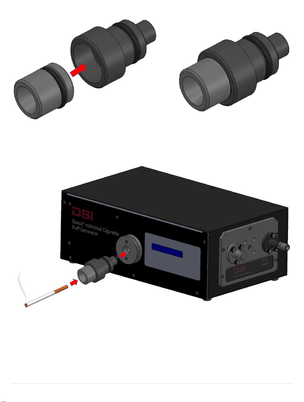
Figure 9
The cigarette can then be inserted into the holder. (Fig 10)
10 |
Figure 10
P a g e
014010-001 Rev 01
©2019 Data Sciences International.
Page 11

Note: In order to light a regular cigarette, the user will need to wait for the unit to start puffing and time
the moment of lighting with the Draw (Inhalation) part of the cycle. This occurs after a distinct audible
pause in the sounds of the unit; the lighter can be held to the tip of the cigarette for several seconds
starting with this pause so the draw period ignites the tobacco within the cigarette tip.
INDIRECT SMOKE CONTAINMENT
An optional containment tube is available that can be connected around the adapter to capture the smoke from
the cigarette tip. By use of another push flow source, this indirect smoke can then be directed out toward a fume
hood, exposure chamber, filter, etc. (Fig 11)
Figure 11
11 |
P a g e
014010-001 Rev 01
©2019 Data Sciences International.
Page 12

OP E R A T IO N
PERIOD
The Period is the length of the draw part of the cycle in seconds. The cycle is split 2/3 draw (inhalation), 1/3 return
(exhalation). The Period can be set from 1 to 3 seconds in 0.5 second increments. (Fig 12)
Example: A Period setting of 2.0 will draw on the cigarette for 2.0 seconds and return over 1.0 seconds.
Figure 12
Use the Up/Down arrows to choose the desired setting and press OK.
PUFFS / M I N
The Puffs/min setting determines the frequency of draw cycles. This can be set from 1 to 5 puffs/minute in 1
puff/minute increments (Fig 13). Example: A Puffs/min setting of 3 will result in puffs that begin every 20 seconds.
Figure 13
Use the Up/Down arrows to choose the desired setting and press OK.
VO L UM E
The Volume setting determines how much air will be drawn during a puff. This can be set from 35 to 55 ml in 5 ml
increments (Fig 14). Example: A Volume setting of 45 means 45 ml of smoke-containing air will be drawn through
the cigarette and delivered as direct smoke.
P a g e
12 |
014010-001 Rev 01
©2019 Data Sciences International.
Page 13
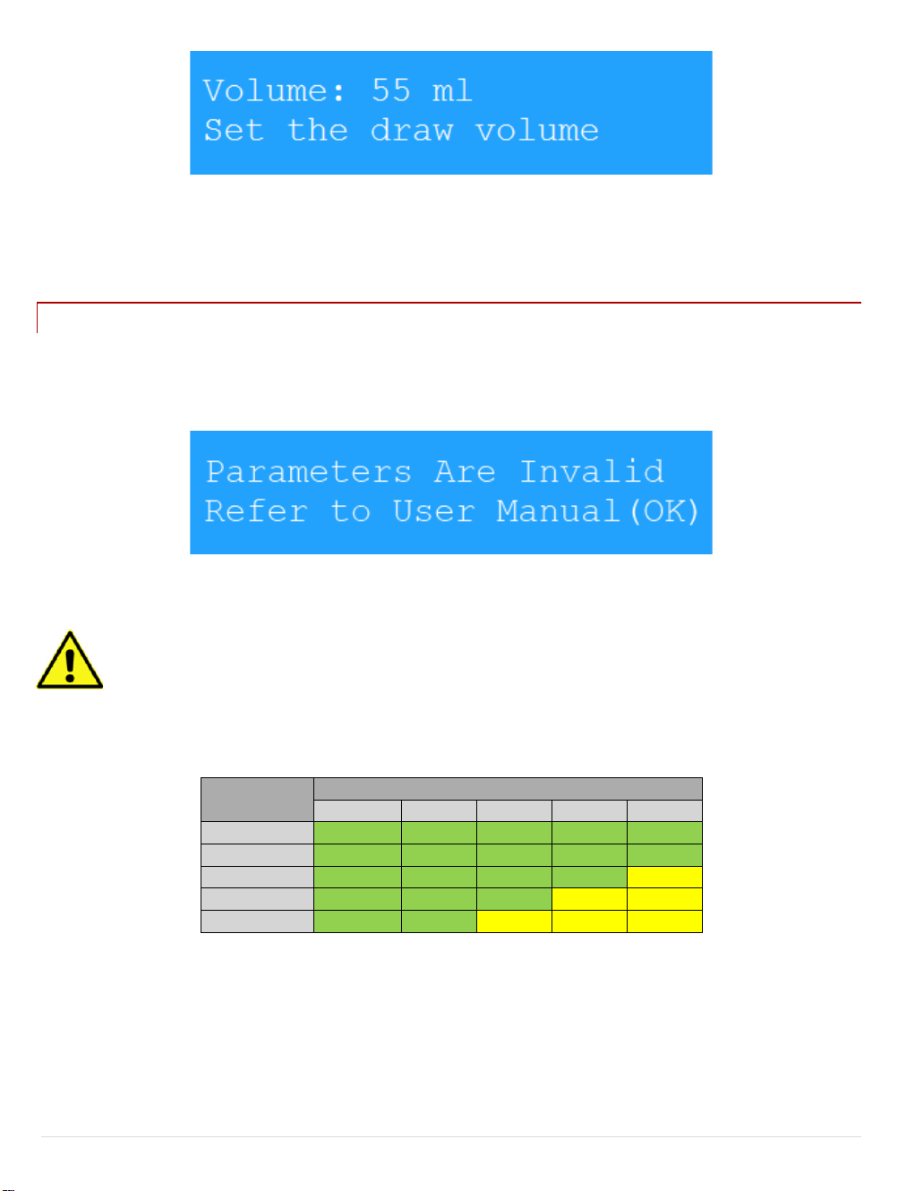
Period
Puffs/min
1 2 3 4 5
1.0
1.5 2.0
Caution
2.5
Caution
Caution
3.0
Caution
Caution
Caution
Figure 14
Use the Up/Down arrows to choose the desired setting and press OK.
RECO M ME N D E D R A NGES
While each of the settings above can be set as described, some combinations are not recommended. If an
improper combination has been selected the following error screen will be displayed. (Fig 15)
Figure 15
Press OK and adjust one or more settings to build a recommended combination.
WARNING: Operating outside the recommended range of combinations can shorten the Individual
Cigarette Puff Generator’s life.
The chart below shows recommended settings combinations. (Fig 16)
Figure 16
13 |
P a g e
014010-001 Rev 01
©2019 Data Sciences International.
Page 14

CIG A R E T T E T IM E
The Cigarette Time setting specifies how long the smoke machine should smoke each cigarette (Fig 17). Depending
on the length of the cigarettes being used and other atmospheric factors, this time may need to be adjusted. This
setting can range from one to ten minutes in fifteen second increments. If using a regular cigarette, the ideal
smoke time should be set so that approximately ¼” or 6mm of tobacco is left on the cigarette. This allows for
deviations in manufacture of cigarettes and prevents the burning of the filter elements.
Figure 17
Use the Up/Down arrows to choose the desired setting and press OK. Note: This setting can be changed “on the
fly”. While the ember unit is smoking cigarettes the time remaining will periodically be displayed on the screen.
Pressing up/down will add/subtract 15 seconds to the time remaining. It is useful to watch the first cigarette and
make the necessary adjustments to the smoke time in order to produce the best results for the remaining,
unsupervised cigarettes.
SMOKE P UM P
This function is not usable on the Individual Cigarette Puff Generator. Do not enable the Peristaltic Pump option or
else the internal lung and actuator mechanisms of the unit will be deactivated.
WARNING: If the Peristaltic pump option is enabled, the unit will not work.
ECIG A R E T T E M O D E
The eCigarette mode should never be disabled on the Individual Cigarette Puff Generator, even for regular
cigarettes.
WARNING: If the eCigarette mode is disabled, the unit will not work.
P a g e
14 |
014010-001 Rev 01
©2019 Data Sciences International.
Page 15

SER V I C E M O D E
This menu option (Fig 18) is set only before you plan to clean the unit (see Maintenance section below).
Figure 18
SYSTEM OPER A T I O N
OPERAT I O N AL S T E P S F OR A N ELECTRONIC CIGARETTE
The Individual Cigarette Puff Generator performs a number of operations to simulate a human smoking the
cigarette. These steps are outlined below.
1. The user inserts an eCigarette in the appropriately shaped holder on the front of the unit
2. The user pushes the Start button on the console
3. The artificial lung, inhalation actuator, and exhalation actuator work in tandem to smoke the eCigarette to
the parameters set previously via the user console
MA I NT E N A N C E
Because of the nature of the product and application, cleaning is an essential maintenance focus. All flow paths
will collect tar and should be serviced as needed. This section explains how to properly maintain your DSI
Individual Cigarette Puff Generator and keep it working in top condition. If you regularly perform the required
routine maintenance on your generator (shown in Figure 19 below), you will increase its working life and minimize
the chance that a failure will occur during use.
As smoke passes through the generator, tar is deposited in the tubes, cartridges, O-rings, and other internal
components of the generator. To prevent this liquid tar from slowly turning into a solid sludge that can impair the
Individual Cigarette Puff Generator’s performance, the liquid tar must be removed on a daily basis from the two
direct smoke cartridges (described below). The cleaning process is quick and easy, and if you do it every single day,
the process becomes part of your shutdown and start-up routine and takes just minutes to complete.
P a g e
15 |
014010-001 Rev 01
©2019 Data Sciences International.
Page 16
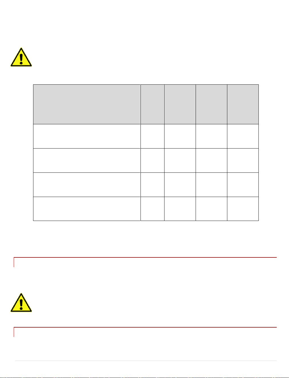
Description of Required Routine
Maintenance
Daily
Every
week or
200
cigarettes*
Every two
weeks or
400
cigarettes*
Every
month or
800
cigarettes*
Clean cartridges with isopropyl alcohol (IPA).
X
Brush the inside of the cartridges.
Grease all the O-rings.
X
Inspect all cartridge O-rings and replace, if
brittle.
X
Brush the inside of the transverse lung pipe.
X
Thereafter, the required routine maintenance depends on either 1) the number of cigarettes the generator has
smoked, or 2) the time that has elapsed since a particular maintenance task was last performed. A schedule of
required maintenance tasks for the generator is shown in Figure 19 below.
Note: The below recommendations are based on smoking regular tobacco cigarettes. Electronic
cigarettes produce less contamination and tar so you may be able to perform these steps less frequently.
* Whichever comes first.
Figure 19
These maintenance tasks are described in more detail in the following sections.
AS H T R A Y S
If using regular tobacco cigarettes, be sure to have an ash tray or water receptible beneath the cigarette to capture
the discarded ash.
Warning: Hot ashes should be handled carefully and placed in water or a nonflammable container.
CLEAN I N G T H E CARTR IDGES
16 |
P a g e
014010-001 Rev 01
©2019 Data Sciences International.
Page 17
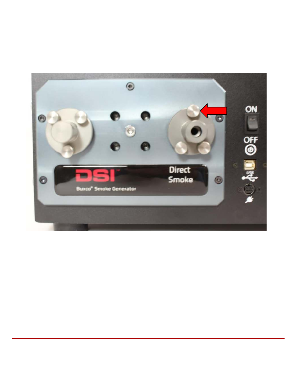
The cartridges should be cleaned at the end of every day that any number of cigarettes have been smoked. The
purpose of this daily cleaning is to prevent liquid tar from accumulating and drying out over time, creating a sludge
that will negatively affect the generator’s performance.
1. Locate the two smoke cartridges in the left side panel of the generator.
2. Remove the three knurled retaining screws (marked with a red arrow in Figure 20) that attach each cartridge
to the generator.
Figure 20
3. Pull the cartridges out of the generator and place them in a glass container with enough isopropyl alcohol
(IPA) to completely submerge the cartridges. Keep the cartridges submerged overnight to soak.
4. After soaking overnight, dry the cartridges (both inside and outside) with a paper towel, reinsert them into the
generator, and re-install the three retaining screws, which should be hand tightened. Note that the position of
the screw holes in the left and right cartridge prevents you from inserting a cartridge in the wrong hole. If the
holes won’t align, the cartridge is in the wrong hole.
BRUS H I N G O U T T HE CARTRIDGES AND GREASING THE O -R I N G S
P a g e
17 |
014010-001 Rev 01
©2019 Data Sciences International.
Page 18
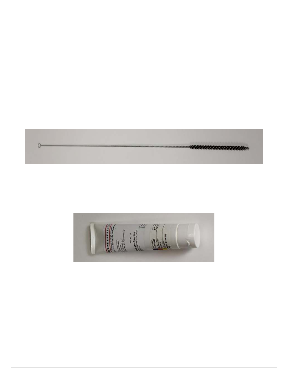
Every week, or after 200 cigarettes have been smoked, the internal surface of the direct smoke cartridges should
be brushed out to prevent tar build-up, and all the O-rings should be greased. A special bore brush and necessary
grease have been provided in the generator’s maintenance kit. (Fig 21 & 22)
1. Remove the two smoke cartridges by unscrewing the three retaining screws and pulling the cartridges out of
the generator.
2. Place the cartridges in isopropyl alcohol (IPA) overnight to soak.
3. After the cartridges have been soaked overnight, remove the cartridges from the IPA and dry them (both
inside and outside) using a paper towel.
4. Locate the bore brush (Fig 21) in the generator’s maintenance kit.
Figure 21
5. Run the bore brush several times in and out of the internal bore of each cartridge.
6. Locate the tube of O-ring grease in the generator’s maintenance kit. (Fig 22)
Figure 22
7. Using your finger, rub a small amount of grease onto the four external O-rings on the left cartridge and the
two external O-rings on the right cartridge. (Fig 23)
18 |
P a g e
014010-001 Rev 01
©2019 Data Sciences International.
Page 19
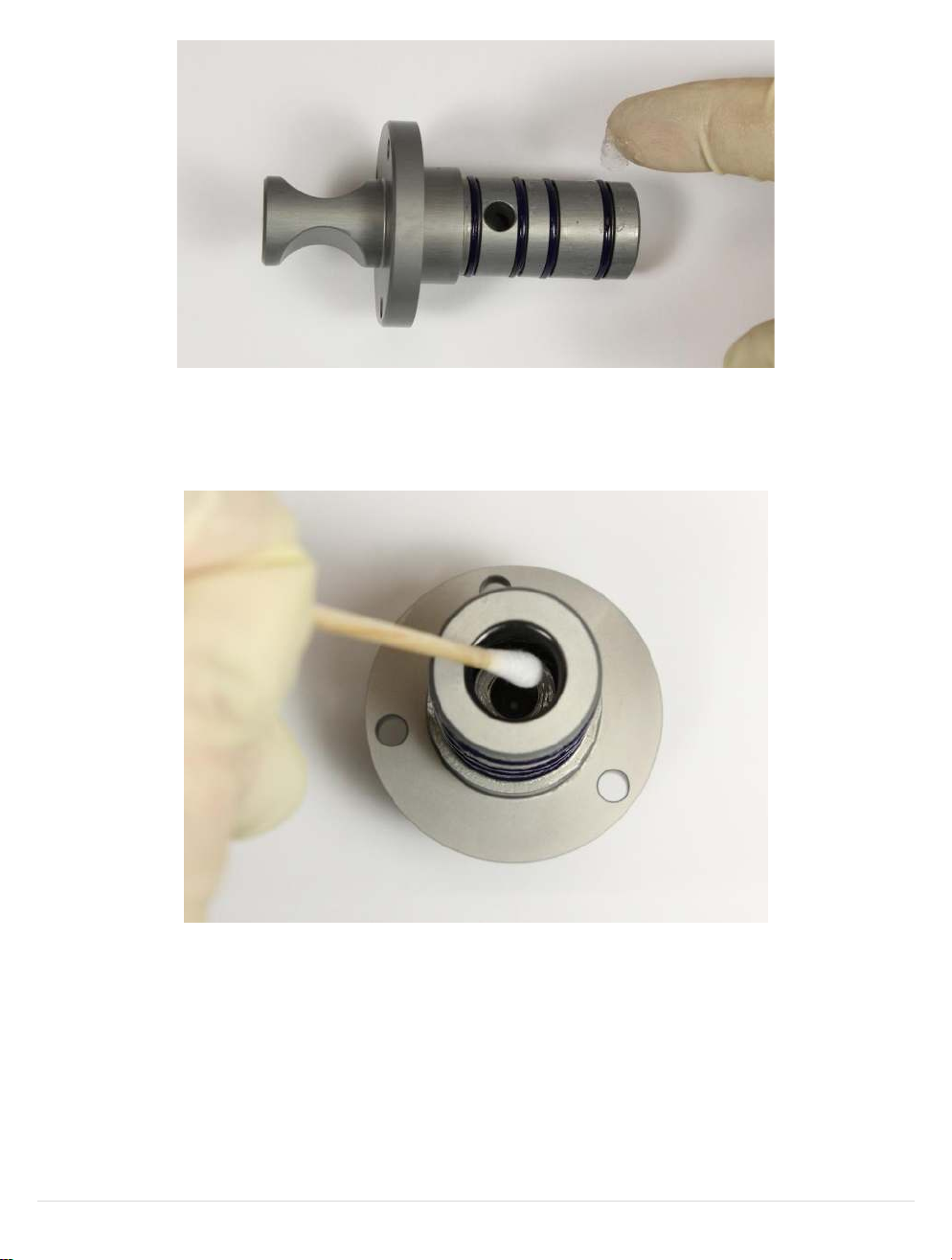
Figure 23
8. Using a cotton swab, rub a small amount of grease onto the internal O-rings inside the left and right cartridge.
Note that there are two internal O-rings in each cartridge and both should be lightly lubricated. (Fig 24)
Figure 24
9. Reinsert the cartridges into the generator and re-install the three retaining screws, by hand-tightening. If the
screw holes won’t align, the cartridge is in the wrong hole.
10. Clean the bore brush in IPA after maintenance is complete.
19 |
P a g e
014010-001 Rev 01
©2019 Data Sciences International.
Page 20
IN S P E C T I N G AL L C ARTI D G E O -RIN G S
Every two weeks, or after 400 cigarettes have been smoked, the internal and external O-rings on the two direct
smoke cartridges must be inspected for the following defects:
• Cracking, distortion, or other obvious visual flaws
• Brittleness or lack of flexibility
Rings with any of the above indications should be replaced using a new ring from the generator’s maintenance kit.
Rings with no defects may be reused.
1) Remove the two direct-smoke cartridges by unscrewing the three holding screws and pulling the cartridges
out of the generator.
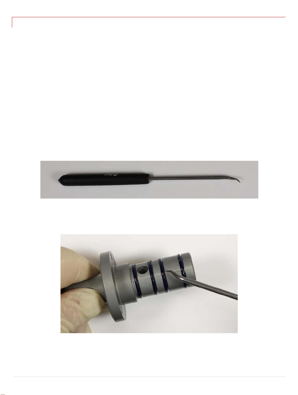
2) Locate the “O-ring removal tool” (Fig 25) in the generator’s maintenance kit.
Figure 25
3) Put on rubber gloves (so you don’t handle any tar-contaminated components) and remove (using the O-ring
removal tool in Figure 25) all the external O-rings from the two cartridges. (Fig 26)
Figure 26
20 |
P a g e
014010-001 Rev 01
©2019 Data Sciences International.
Page 21

4) Feed the removal tool into the internal bore of the cartridge, and pry part of the O-ring out of its seating
groove. Grab the O-ring with a pair of tweezers and completely remove it. Please note that there are two
internal O-rings in each cartridge.
5) Inspect all O-rings for the following defects:
• Visual defects—such as cracking or distortion.
• Brittleness or lack of flexibility.
Discard all rings that display any of the above symptoms.
6) Place any rings that pass inspection into a beaker of isopropyl alcohol (IPA), add the two cartridges, and soak
these components overnight. This will ensure that the seating grooves on the cartridges as well as the old
rings are thoroughly clean before being re-installed.
7) After soaking overnight, use the bore brush (Fig 21) to clean the inner bore and O-ring grooves and briefly dip
them back into the IPA. Remove all components (cartridges, O-rings) from the IPA and dry them with a paper
towel.
8) Using your fingers, install (cleaned or new) O-rings in the external seating grooves on the cartridges.
9) Please note that installing (cleaned or new) O-rings in the internal seating grooves of the cartridge is more
difficult. The best way to do this is as follows:
a) Using your fingers, bend the O-ring into an oval and push it into the bore.
b) Take a small screwdriver (after checking to make sure the blade doesn’t have any sharp edges that could
damage the O-ring) and push the ring until part of it makes contact and slips into the seating groove.
c) Starting from the point where the ring is already seated, carefully work the remainder of the O-ring into
the seating groove.
d) This is important! Double-check that both rings are properly seated (by gently prodding the entire
circumference with the screwdriver) before moving on to the next step.
10) Reinsert the cartridges into the generator, and re-install the three retaining screws, which should be hand
tightened. If the screw holes won’t align, the cartridge is in the wrong hole.
BRUS H I N G T HE I NS I D E O F THE TRANSVERSE LUNG PIPE
Every month or after 800 cigarettes have been smoked, brush out the inside of the transverse lung pipe to remove
any accumulated tar. The Individual Cigarette Puff Generator must be powered down before you attempt to access
P a g e
21 |
014010-001 Rev 01
©2019 Data Sciences International.
Page 22

or clean the transverse lung pipe. If the generator is powered up during disassembly or cleaning you risk personal
injury or damage to the system.
1) Locate the blue down-arrow on the generator’s control panel and press it eight times to bring up the “Service
Mode” menu. (Fig 27)
Figure 27
2) Press the OK button. This moves the lung’s actuators into a safe position for cleaning the transverse lung pipe.
3) Power down the generator (by turning its main power switch to OFF) and remove the power cord from the
power socket (for added safety).
NOTE: You must power down the Individual Cigarette Puff Generator before accessing or cleaning the
transverse lung pipe.
4) Using the hex key provided in the maintenance kit, unscrew and remove the five hex nuts (Fig 28) on the
cartridge attachment plate.
Figure 28
22 |
P a g e
014010-001 Rev 01
©2019 Data Sciences International.
Page 23
½"
Access nut
½"
Access nut
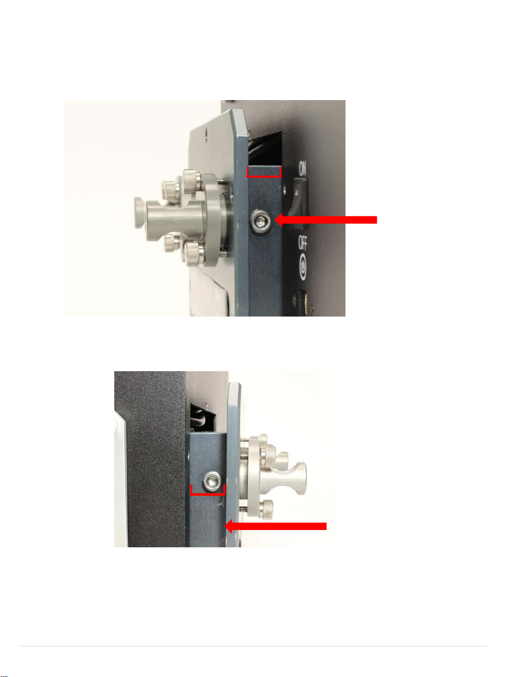
5) Grasp the attachment plate firmly and gently pull it out of the Individual Cigarette Puff Generator housing to a
distance of no more than half-an-inch (shown in Figure 29 below).
• Pull slowly and firmly. Do not tug on the attachment plate; if you do, you risk damaging the wiring.
• Do not remove the attachment plate more than one-half inch from the generator
Figure 29
6) Unscrew (using the hex key) and remove the transverse lung-pipe access nut (shown in Figure 29 above).
Figure 30
7) Remove the access nut on the opposite side of the assembly (shown in Figure 30 above).
P a g e
23 |
014010-001 Rev 01
©2019 Data Sciences International.
Page 24
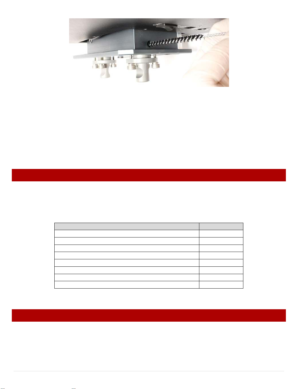
Figure 31
Description of Part
Part Number
Inner O-rings
009450-001
Outer O-rings
009460-001
Tube of O-ring grease
601-2524-053
O-ring removal tool
007579-001
Bore brush
008850-001
Maintenance Kit (includes the preceding five parts)
601-2056-001
Direct-smoke cartridges Kit (includes all needed O-rings)
601-6050-001
Lung assembly—complete
601-2112-001
8) Locate the bore brush in the generator’s maintenance kit. Run it several time through the transverse lung pipe
to remove any accumulated tar (Fig 31).
9) Re-assemble the unit by doing the following.
• Install and tighten the two lung-pipe access nuts.
• Gently push the attachment plate back into the generator.
• Install and tighten the five hex nuts to secure the attachment plate to the generator.
PARTS LIST
The table below (Fig 32) lists the spare parts you may need to keep your Individual Cigarette Puff Generator
running properly. We suggest you keep all these parts in stock, so none of your critical experiments are
compromised for lack of a needed part.
Figure 32
REPLACING T H E L U N G
The routine maintenance steps listed above are crucial to extend the functionality of the Individual Cigarette Puff
Generator. However, after months or years of use, the inhalation/exhalation actuators or lung itself may
eventually become corroded by accumulated tar. When this happen, the best option is to replace the entire lung
assembly with a new one.
P a g e
24 |
014010-001 Rev 01
©2019 Data Sciences International.
Page 25
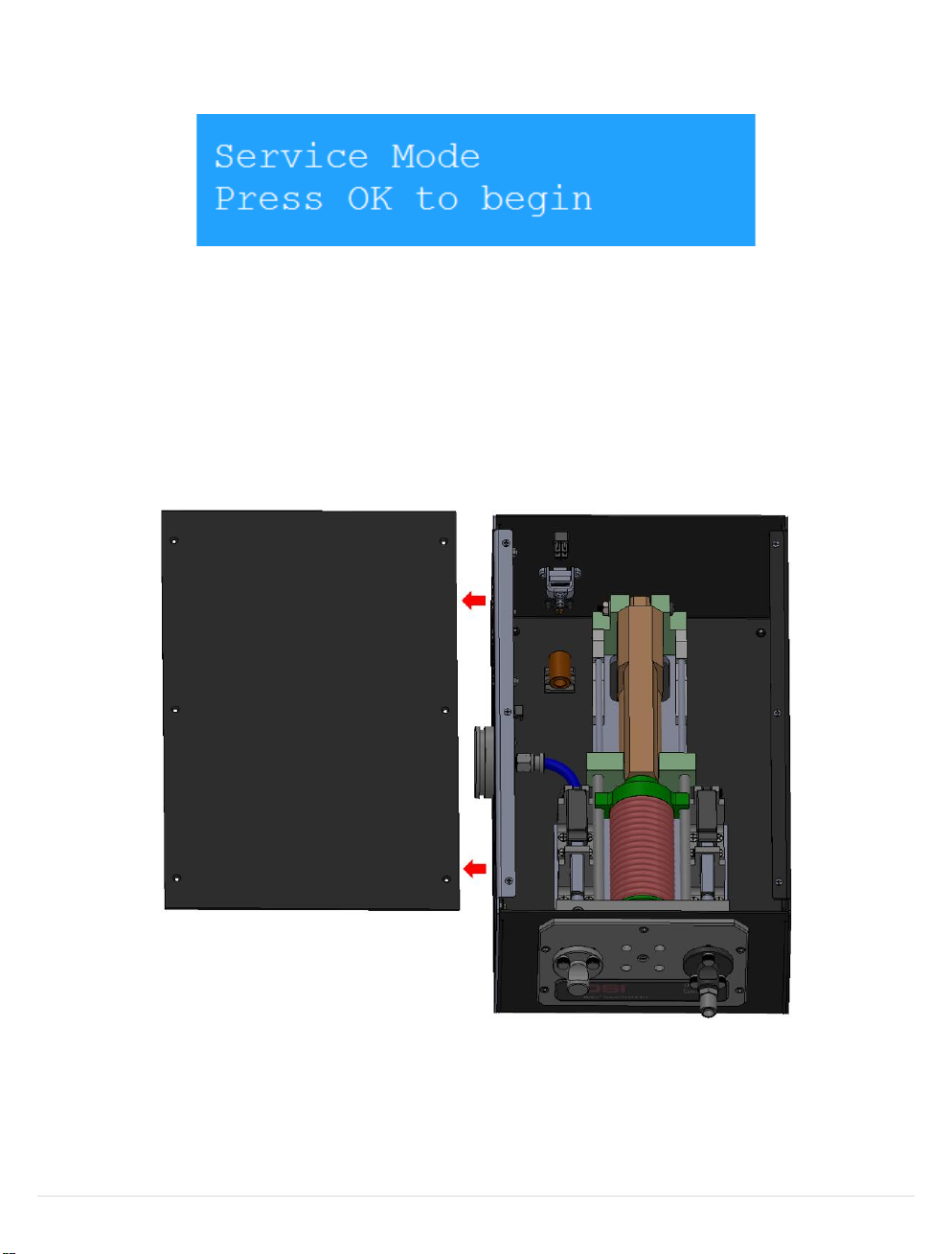
1) Locate the blue down-arrow on the generator’s control panel and press it eight times to bring up the “Service
Mode” menu. (Fig 33)
Figure 33
2) Press the OK button. This moves the lung’s actuators into a safe position for removing the lung.
3) Power down the Individual Cigarette Puff Generator (by turning its main power switch to OFF) and remove the
power cord from the power socket.
4) Unscrew the screws around the top of the unit to remove the top plate, revealing the inside of the unit. (Fig
34)
25 |
Figure 34
P a g e
014010-001 Rev 01
©2019 Data Sciences International.
Page 26
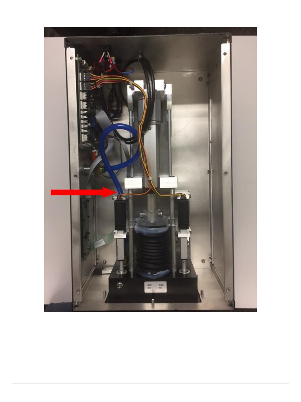
5) Disconnect the blue tube that connects from the cigarette adapter to the Inhalation actuator. (Fig 35)
26 |
Figure 35
P a g e
014010-001 Rev 01
©2019 Data Sciences International.
Page 27

6) Disconnect the connections for the Lung and the Inhalation and Exhalation actuators from the motherboard.
(Fig 36)
27 |
Figure 36
P a g e
014010-001 Rev 01
©2019 Data Sciences International.
Page 28

7) Using the hex key provided, unscrew and remove the five hex nuts on the cartridge attachment plate. (Fig 37)
Figure 37
8) Now that the tubing, actuators, and lung are all disconnected from the inside of the unit, the entire lung
assembly will slide right out of the unit.
9) The replacement lung can be inserted, and the new connections outlined in steps 5-6 above can be made.
NOTE: The Exhalation actuator is the one that is in-line with the Direct Smoke port on the side of the unit
10) Contact Technical Support to assist with setting the new Min/Max Values of the new lung actuators. NOTE:
This will require a computer with internet access and the ability for Technical Support to remotely access that
computer, as well as a USB cable connected to the Individual Cigarette Puff Generator.
28 |
P a g e
014010-001 Rev 01
©2019 Data Sciences International.
Page 29

TECHNICAL SUPPO R T
DSI™ is available to help you with your questions and concerns. Should you hit a road block or need some
additional training, please feel free to contact us. We are happy to help!
DSI TECHNIC AL SUPPORT —NOR TH AMERICA
Email: [email protected]
Toll-free in U.S. and Canada
Phone: 1-800-262-9687
Monday through Friday: 8 AM to 5 PM CST
(except Holidays)
DSI TECHNIC AL SUPPORT —EUR OPE
Email: [email protected]
Phone: +44 1359 259400
Monday through Friday: 8 AM to 5 PM CET
DSI TECHNIC AL SUPPORT —ALL OTHER COUNTRIES
Phone: +1-651-481-7400
29 |
P a g e
014010-001 Rev 01
©2019 Data Sciences International.
Page 30
APPENDIX
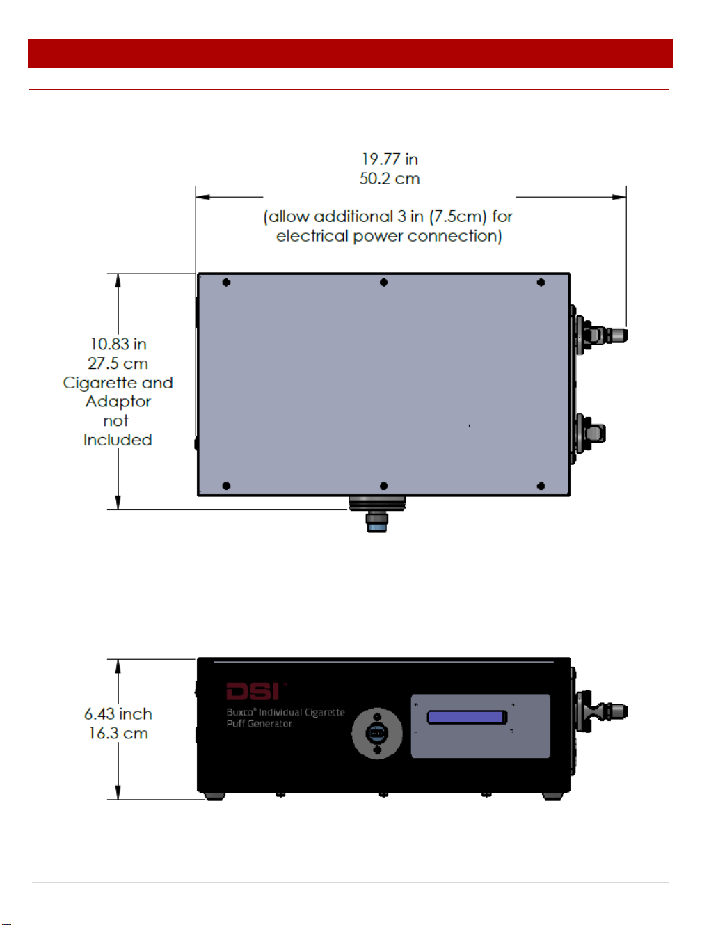
DIMENS I O N S
30 |
P a g e
014010-001 Rev 01
©2019 Data Sciences International.
 Loading...