

Page 1

VG6000 Digital Gateway
Administrator
Installation and Configuration Guide
06VG60M.DG1.01a.EN1
Page 2

DSG, DSG logo, InterPBX, InterServer, Blaze Series, Savanna Series, VG5000, VG6000, IP580, IP500,
InterClient, NAT Proxy, SIP Proxy and S300X are trademarks of DSG Technology. Windows and
Outlook Express are trademarks of Microsoft Inc. Other names used here are trademarks of their
respective owners.
Copyright © DSG Technology Inc. All rights reserved.
7F, 222 Cheng-Te Road, Sec. 4, Taipei, Taiwan 111
Tel: 886 2 88615558
Fax: 886 288615557
E-mail:sales@dsg.com.tw
http: //www.dsgtechnology.com
Page 3

Table of Contents
Table of Contents
Chapter 1 Installing VG6000 Digital Gateway...........................................................5
Before You Start......................................................................................................6
Installing VG6000 Digital Gateway........................................................................6
Chapter 2 Configuring Digital Gateway ..................................................................11
Configuring Trunks ..............................................................................................12
Configuring Channels .......................................................................................... 15
Reset Trunks .........................................................................................................17
Enable and Disable Channels ...............................................................................18
Chapter 3 Settings on InterPBX System ...................................................................21
Adding Digital Gateway....................................................................................... 22
Setting Trunk Parameters..................................................................................... 24
Setting Port Parameters ........................................................................................24
Setting Digital Trunk ARS .................................................................................... 27
Chapter 4 Line Status and Event ..............................................................................30
Line Status ............................................................................................................31
Event .....................................................................................................................31
System Specifications ..................................................................................................33
3
Index ............................................................................................................................34
Page 4

Page 5

Chapter 1 Installing VG6000 Digital Gateway
5
Chapter 1
Installing VG6000 Digital Gateway
IDSN (Integrated Services Digital Network) is a switched digital network
for voice and data. It provides higher speed alternative to analog
networks.
If you have subscribed ISDN services, you may install DSG VG6000
Digital Gateway allowing you to access ISDN services when using DSG
Blaze or Savanna IP-PBX.
This chapter guides you through the preparation, installation and basic
configuration of DSG VG6000 Digital Gateway.
Page 6
6
Chapter 1 Installing VG6000 Digital Gateway
Before You Start
DSG VG6000 Digital Gateway is an electronic product. Please follow the
recommendations below when you install or operate your system in
order to avoid any injury and damage.
Safety Recommendations
Always use ESD-preventive tools when you plug the power cord. Do not
disassemble or remove chassis cover of the system. If there is any
problem of your system, please contact our service representatives.
Environmental Prerequisites
DSG VG6000 Digital Gateway needs to be installed in clean, dry,
adequately ventilated areas. The system can be placed in a control room
or on a rack. Please remain the control room in a suitable temperature
and adequately ventilated environment.
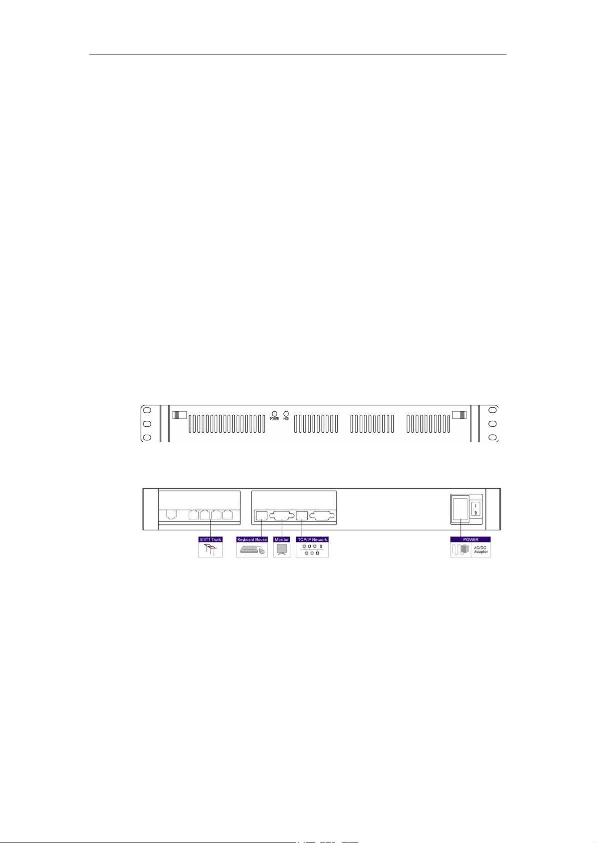
Installing VG6000 Digital Gateway
Figure: Digital Gateway Front Panel
Figure: Digital Gateway Rear Panel
Step 1. Connecting Power Cord
Plug one end of the power cord to the power connector on the rear panel
of VG6000. Plug the other end of the power cord into a power outlet.
After you turn on the power switching on the rear panel, you can verify
the function by checking if the LED labeled “Power” is on.
Step 2. Connecting Monitor, Keyboard and Mouse
Page 7

Chapter 1 Installing VG6000 Digital Gateway
7
Plug in the cord of your monitor, keyboard and mouse to the appropriate
socket on the rear panel of VG6000.
Step 3. Connecting to LAN
You need to connect VG6000 to your existing Ethernet network. Connect
an Ethernet cable from the network RJ45 port on VG6000 to any
10/100BaseT RJ45 port on a switching hub.
The default IP settings of VG6000 are as follows. You may change it to
conform to your network later.
Default IP Address: 192.168.1.206
Default Gateway: 192.168.1.254
Default Subnet Mask: 255.255.0.0
Step 4. Connecting Trunk Cables
Attach a cable from DSC/CSU equipment provided by your carrier or a
PBX’s T1/E1 interface if you prefer to set a tie line to a T1/E1 interface on
VG6000.
Pin signals for connecting to DSC/CSU (DB-15) provided by your carrier
RJ-48 Pin
(on T1/E1 PIC)
(Data numbering form)
DB-15 Pin
(Data numbering
form)
Signal
1 11 RX/Ring/- <-->RX/Ring/-
2 3 RX/Tip/+ <-->RX/Tip/+
4 9 TX/Ring/- <-->TX/Ring/-
5 1 TX/Tip/+ <-->TX/Tip/+
3 4 Shield/Return/Ground
6 2 Shield/Return/Ground
Pin signals for connecting to other PBX’s T1/E1 interfaces to set a Tie
Line
RJ-48 Pin
(on T1/E1 PIC)
(Data numbering form)
RJ-48 Pin
(Data numbering
form)
Signal
1 4 RX/Ring/- <-->TX/Ring/-
2 5 RX/Tip/+ <-->TX/Tip/+
4 1 TX/Ring/- <-->RX/Ring/-
Page 8
8
Chapter 1 Installing VG6000 Digital Gateway
5 2 TX/Tip/+ <-->RX/Tip/+
3 3 Shield/Return/Ground
6 6 Shield/Return/Ground
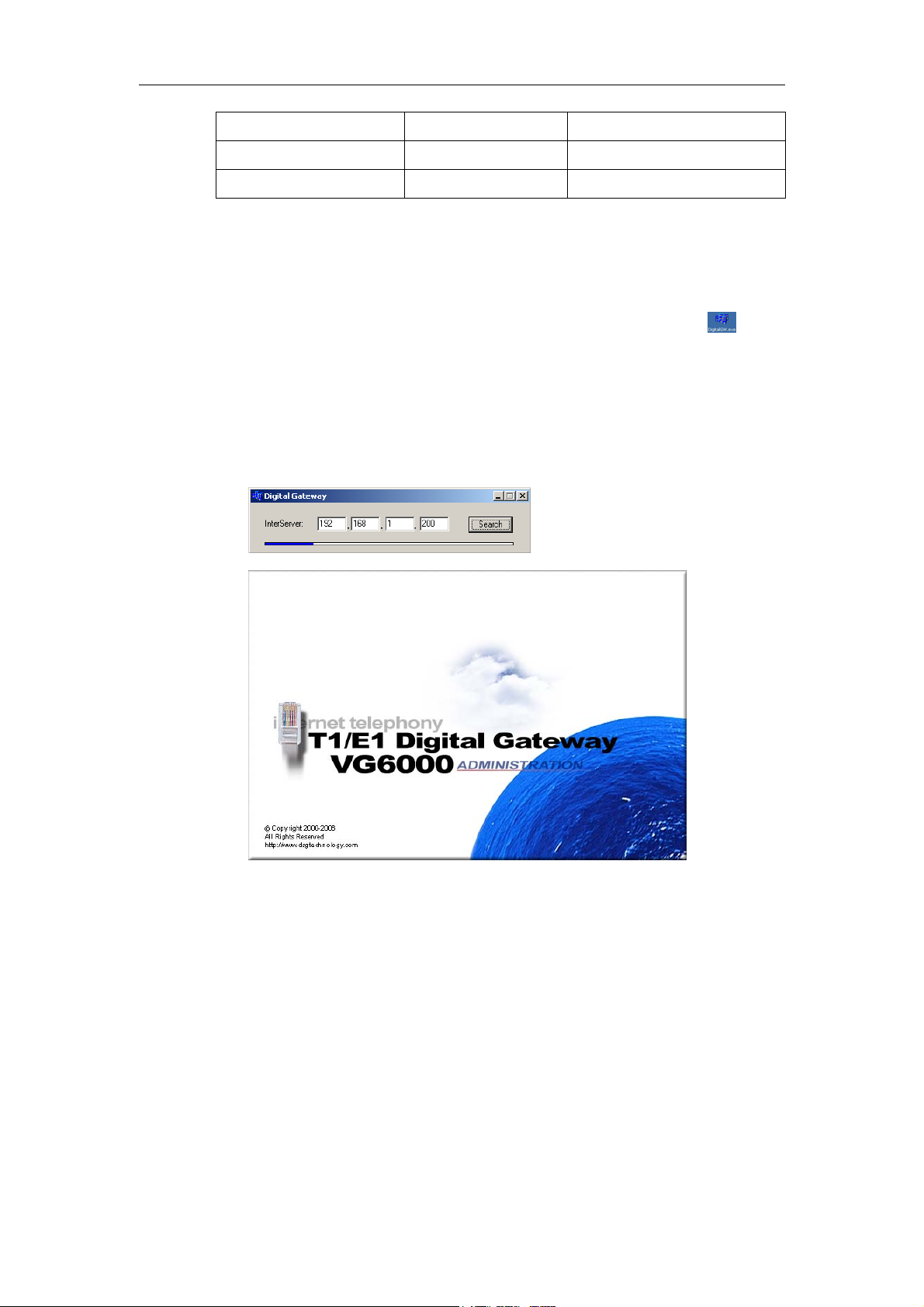
Step 5. Launch VG6000 Program
1. Turn on the power of VG6000 and you will be prompted Windows
OS.
2. From your desktop, double click on DigitalGW.exe shortcut
or
go to C:\DG1.00a\Setup\DigitalGW.exe to launch the program. The
name of DG1.00a folder varies in your software version.
3. On the prompt window, input your InterServer’s (Blaze or Savanna)
IP address and click the Search button. It will take about 10 seconds
to launch the program.
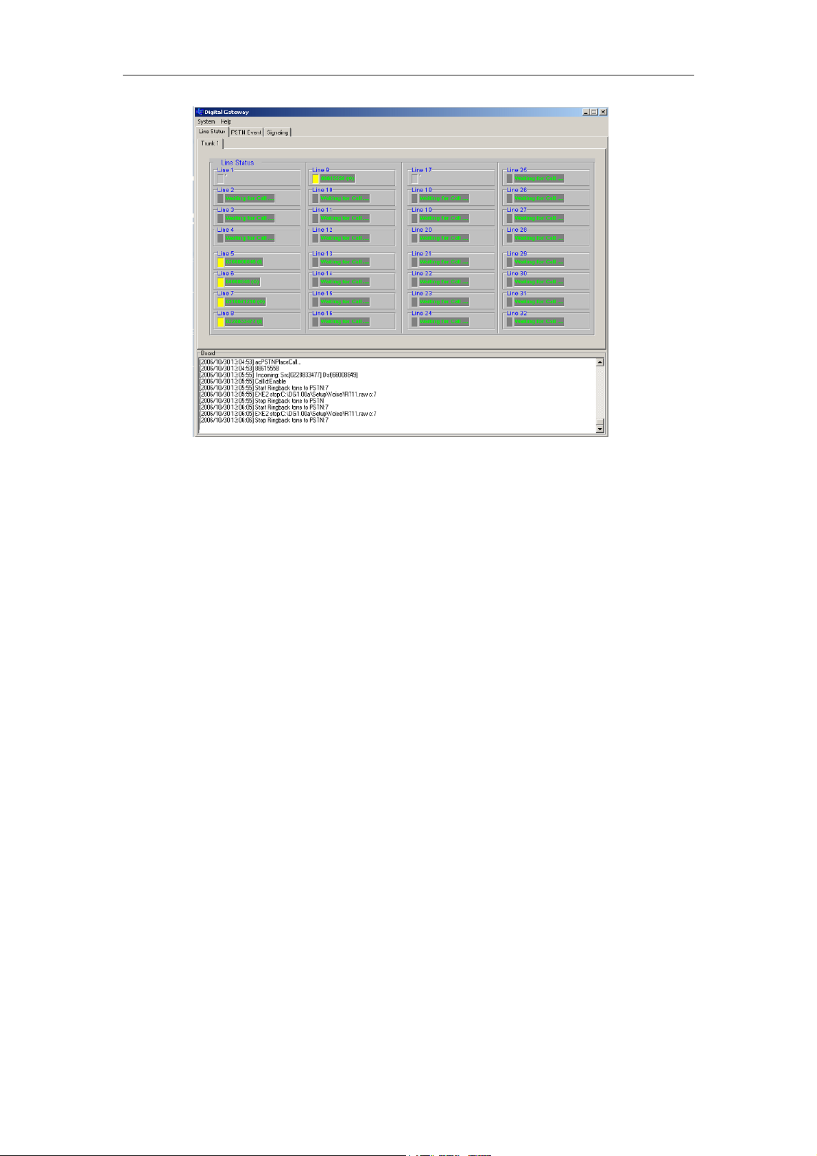
Step 6. VG6000 Line Status
After you launch the program, you will see “Line Status” tab. Each line
will have its status indicator and description.
Page 9
Chapter 1 Installing VG6000 Digital Gateway
Lines are gray out when not configured. You may edit them later.
9
When connected and properly set, line description is in green text.
Line indicator is in yellow when in use. Numbers of incoming call
(represented as: I) or outgoing call (represented as: O) are displayed
at the description field.
When line indicator is in gray color, the line is idle.
Page 10

Page 11

Chapter 2 Configuring Digital Gateway
Chapter 2
Configuring Digital Gateway
11
This chapter guides you through the details of configuring VG6000
Digital Gateway. You will need to input the required parameters and set
its direction to your IP-PBX System. Each VG6000 can support one
IP-PBX system.
Page 12

12
Chapter 2 Configuring Digital Gateway
Configuring Trunks
You need to properly set trunk and channel parameters to conform to the
requirement of your ISDN services.
1. Double click on DigitalGW.exe shortcut or go to
C:\DG1.00a\Setup\DigitalGW.exe to launch the program.
2. On the main menu, choose System>Setup. You will be prompt System
Configuration window.
3. Select Board Info tab to edit relevant parameters.
In Trunk Setup field:
Trunk: Select a trunk line from the list. You may set different
protocol for different trunk line.
Protocol Type: The ISDN was implemented in many different
vendors. Some of those are well defined and have a specification.
Select one from the list.
- E1_EURO_ISDN
- T1_CAS
- T1_RAW_CAS
- T1_TRANSPARENT
- E1_TRANSPARENT_62
- E1_TRANSPARENT_60
- E1_MFCR2
- E1_CAS_R2
- E1_RAW_CAS
Page 13

- T1_NI2_ISDN
- T1_4ESS_ISDN
- T1_5ESS_9_ISDN
- T1_5ESS_10_ISDN
- T1_DMS100_ISDN
- J1_TRANSPARENT
- T1_NTT_ISDN
- E1_AUSTEL_ISDN
- E1_HKT_ISDN
- E1_KOR_ISDN
- T1_HKT_ISDN
- E1_QSIG
- E1_TNZ_ISDN
- T1_QSIG
- V5_1_AN
Chapter 2 Configuring Digital Gateway
13
- V5_1_LE
- V5_2_AN
- V5_2_LE
- T1_IUA
- E1_IUA
Line Code: Line Coding is the pattern that data assumes as it
propagated over a communications channel.
- B8ZS
- AMI
- HDB3
Termination Side: For ISDN only. Select the ISDN termination to be
either user or network termination.
- User_Side
- Net_Side
Framing: Framing is a concept common to both DS1 and CEPT1
standards, though they differ in how they implement framing. A
frame is the set of 24 (DS1) or 32 (CEPT1) 8-bit time slots that is
treated as a single transmission unit, the superframe (also called D4
framing) and the extended superframe (ESF).
- Extended_Super_Frame
- Super_Frame
Clock Master: Select the trunk clock source. When choosing
Clock_Master_Off, the clock is recovered from the line. When
Page 14

14
Chapter 2 Configuring Digital Gateway
choosing Clock_Master_On, the trunk clock source is provided by
the internal clock source.
- Clock_Master_Off
- Clock_Master_On
Line Build Out Loss: This setting is applicable only to T1 trunks and
used to control loss for different lengths of the line.
- ac0DB
- ac7_5DB
- ac15DB
- ac22_5DB
In Digital Board Setup field:
PCM Law Select: Select the PCM companding law (ether μ-Law or
A Law) to correspond with the one used in the TDM bus/Framers
bus.
- µ-Law
- A Law
TDM Bus Type: Must be selected to FRAMERS.
- Mvip_Bus
- Sc_Bus
- Framers
- H100_Bus
- External_Tdm_Bus
TDM Bus Speed: When TDM Bus Type is set to FRAMERS, the TDM
bus speed parameter is meaningless and is ignored.
- 2048 kbps
- 4096 kbps
- 8192 kbps
TDM Bus Source: To synchronize the boards internal PCM highway
and in some cases to drive a clock to an external interface.
- Internal
- Network
- PrimaryMaster
- SecondaryMaster
- NetReference
Call Progress File: This file contains the definitions of the Call
Progress Tone to be detected or generated by the board. Click the
Browse button and select C:\IPGv50\usa_tones.dat.
Page 15

CAS Protocol File: It functions only when your select CAS protocol
type. This file contains the CAS Protocol definition to be used for
CAS-terminated trunks.
Note: When you click the OK button, trunks will be reset. Please make
sure there is no call activity on the system.
Configuring Channels
You may adjust the voice quality for individual channel.
1. Double click on DigitalGW.exe shortcut or go to
C:\DG1.00a\Setup\DigitalGW.exe to launch the program.
2. On the main menu, choose System>Setup. You will be prompt System
Configuration window.
3. Select Channel Info tab to edit relevant parameters.
Chapter 2 Configuring Digital Gateway
15
Trunk: Select the trunk you would like to set from the list. If you
select All, your settings will be adopted to all trunks.
- All
- 1~4
Channel: Select a channel you would like to set from the list. If you
choose All, your settings will be adopted to all channels on the
selected trunk.
- All
- 1~32
Page 16

16
Chapter 2 Configuring Digital Gateway
PSTN Voice Volume: PSTN Voice Volume sets the voice decoder’s
output gain.
- 0~63
PSTN Input Gain: PSTN Input Gain sets the gain at the voice
decoder’s input.
- 0~63
Echo Cancellation: Depends on the voice quality, enable or disable
echo canceller.
- On
- Off
Echo Cancellation Length: When echo cancellation is enabled, set
the echo canceller tail length. When exceeds, actual length is being
clipped.
- 10 mSec
- 15 mSec
- 20 mSec
- 25 mSec
- 30 mSec
- 35 mSec
- 40 mSec
Silence Compression: The silence compression feature reduces
network traffic whenever a period of silence is detected during a
conversation. When there is silence in a conversation, silence
indicator packets will be sent by the system instead of full voice
packets to reduce traffic. Select On or Off to enable or disable this
function.
- On
- Off
DTMF Volume: DTMF Volume sets the output gain for playing
DTMF digits.
- 0~31
Jitter Buffer Factor: Depending on your bandwidth, set the jitter
buffer. The higher value reduces the chance of packet loss during a
call but might cause delays and the lower value will help to transmit
the voice packets faster but might cause packet loss problems.
- 0~13
Source Phone No.: Input the phone number of the trunk provided by
your carrier. When set as a Tie Trunk, assign a number representing
Page 17

Chapter 2 Configuring Digital Gateway
7
this trunk. Notice that the number should conform to your carrier or
regional telecom requirement.
Source Numbering Type:
- Unknown_Number
- International_Number
- National_Number
- Network_Specific_Number
- Subscriber_Number
- Abbreviated_Number
Destination Type:
- Unknown_Number
- International_Number
- National_Number
- Network_Specific_Number
- Subscriber_Number
1
- Abbreviated_Number
Destination Plan:
- Unknown_Numbering_Plan
- Isdn_Numbering_Plan
- Data_Numbering_Plan
- Telex_Numbering_Plan
- National_Numbering_Plan
- Private_Numbering_Plan
- Reserved_Numbering_Plan
Log Trac File: When selected, channel logs will be saved at
c:\DG1.00a\Setup\Log.
Note: When you click the OK button, channels will be reset. Please make
sure there is no call activity on the system.
Reset Trunks
When you would like to reset trunks, go to Main Menu>System>Reset
Trunk. Select a specific trunk and click the OK button to reset.
Page 18

18
Chapter 2 Configuring Digital Gateway
Note: When you click the OK button, trunks will be reset. Please make
sure there is no call activity on the system.
Enable and Disable Channels
You may enable or disable all or some channels for maintenance purpose.
Choose a specific trunk tab and select or deselect to enable or disable
channels.
For example, if you deselect channel 3, 4, 5, 6 on Trunk 1 as below, on
Line Status tab, the disabled channels will be gray out.
Page 19

Chapter 2 Configuring Digital Gateway
19
Page 20

Page 21

Chapter 3 Settings on InterPBX System
21
Chapter 3
Settings on InterPBX System
When adopting VG6000 Digital Gateway, your InterPBX IP
Communication System, including Blaze, Savanna series IP-PBX, needs to
enable the relevant function as well.
You will need to create a VG6000 Digital Gateway list.
Page 22

22
Chapter 3 Settings on InterPBX System
Adding Digital Gateway
You need to set the MAC address of VG6000 Digital Gateway to the
InterServer.
1. Launch the web browser. On the address bar, enter your InterServer’s
IP address. (Please use service port 88.)
2. Click on the Administrator icon and use your user name and
password to login.
3. Go to Main Menu>Gateway Configuration>Digital Line Gateways,
the ”Digital Gateway” list will be displayed.
4. Click the Add button to create a Digital Gateway. Before you add a
new gateway, make sure the relevant License Keys has been added.
5. Input the required data of this gateway.
Name: Enter a name to describe this Digital Gateway.
MAC Address: Enter the MAC address of the Digital Gateway.
You may find the MAC address from the device label.
Page 23

Chapter 3 Settings on InterPBX System
Trunk Number: Enter the available trunk numbers you may use
23
or purchase.
CO Line per Trunk: Input the available channels of each trunk.
For example, input 32 for E1 or 24 for T1.
CO Line Extension Base: Input the starting number of CO Line
extension number. The CO Line extension numbers will be
assigned automatically. For example if you set it as 4000 for an
8-port FXO gateway, the CO Line extension number of this
gateway will be 4000-4007.
Jitter Buffer: From “Jitter Buffer Depth” drop down menu,
depending on your bandwidth and CODEC, start with a Jitter
Buffer with the minimum value. Jitter Buffer will dynamically
adjust its value according to the party you are talking to and the
bandwidth of the call but never below the value you have set. The
higher value of Jitter Buffer will reduce the chance of packet loss
during a call but might cause delays and the lower value will help
to transmit the voice packets faster but might cause packet loss
problems.
Off-Premises and IP address: For Off-Premises Gateways, you
will need to select the check box and enter its “IP Address”. The
IP Address assigned to this Off-Premises Gateways needs to be a
REAL (PUBLIC) IP address.
To Modify a Gateway
To modify, select a gateway from the list and click the Modify button.
You may the change the name, MAC address and set jitter buffer or
change the IP address if it is located off-premises for this gateway. The
software version of the gateway will also be displayed here.
Note: If later on your needs grow and you need to add more trunks or
channels into an existing gateway, you will need to delete the existing
gateway from the list and create a new one with new trunk or channel
numbers.
Note: Please make sure you have available license keys before adding a
new gateway. To check your license key, go to Main Menu>Operation
Management>General Information.
Page 24

24
Chapter 3 Settings on InterPBX System
Setting Trunk Parameters
You can further more set the parameters of each trunk to adjust the voice
quality and other items. Select a gateway you would like to edit from the
list and click the Trunk button to edit each trunk of the selected gateway.
Trunk: Select a trunk you would like to edit from the list.
CO Line Index Bass: Input the starting number of the CO line
display number. For example if you set it as 1, when there is an
incoming call from port 1, the IP phones will display “Incoming Call
CO 1” instead of the extension number of the port, helping you to
identify the CO lines being used.
Transmit Gain: This field edits the TX Gain of the trunk, or how
loud the external party hears your voice. The value here should
conform to the one on Digital Gateway. The default value is 5.
Receive Gain: This field edits the RX Gain of the trunk, or the
volume of incoming calls. The value here should conform to the one
on Digital Gateway. The default value is 5.
DTMF Volume: This field edits the intensity of the DTMF tones in
the trunk. The value here should conform to the one on Digital
Gateway. The default value is 5.
Tie Line: Select Tie Line check box if you would like to establish a tie
to connect the Digital Gateway to other PBX using this trunk.
Setting Port Parameters
You can edit the ring assignment and other settings for individual ports
or channels of a trunk. Select a gateway from the list and click the Port
Page 25

Chapter 3 Settings on InterPBX System
25
Setting button. Select a port from the list and click the Port Parameters
button to edit.
Extension Number: The extension number will be displayed
automatically based on your settings under “CO Line Extension
Base”. You may also change the extension number here.
Description: Input the telephone number or other information for
this port.
Enable: For maintenance purpose, you may need to temporarily
disable some channels. Click the “Enable” check box to enable the
channel or uncheck to disable it.
CODEC: Choose the preferred CODEC from PCM, G.723.1 or G.729
supported by InterPBX Communication System. PCM CODEC
compresses and decompresses voice conversation to 64 Kbps
providing the best speech quality but consumes larger bandwidths.
G.723.1 CODEC uses 5.3/6.3 Kbps, the less bandwidth from the
three choices but may result in poorer call quality and finally G.729,
which uses 8 Kbps.
DID: When selected, incoming calls will be connected to extensions
directly in stead of been picked up by Auto Attendant. This function
is available when you have subscribed the DID service provided by
your carrier. When you would like to set a direct line between two
PBXs connected by Tie Line, you may also enable this function.
Strip Prefix Digit: When the length of the number sent by DID is
longer than your extension numbers, set the digit that needs to be
removed. For example, if the DID prefix and adding number is
Page 26

26
Chapter 3 Settings on InterPBX System
660x-xxxx, but you have 4-digit extension number, set “1” to delete
the first digit sent by your carrier. The default value is 0.
Ring Assignment: Ring Assignment allows you to assign a specific
extension, extension group or AA Menu to answer incoming calls
from a specific CO line or CO Line Group. In the Ring Assignment
field, choose the option of “Local” or “From CO Group”.
- If you select “Local”, input a specific extension number,
extension group or AA Menu access code to answer incoming
calls for this port in Business Hours, Break Hours, After Hours
and Closed. The most common setting is to assign an AA Menu
to answer phone calls. If you would like to play special
greetings for holidays, select the “Enable Holiday” checkbox
and the system will play the assigned greeting from Holiday
List. For more details about AA Menu, Voice Mail and Holiday
settings, please refer to InterPBX Administrator Installation
and Configuration Guide.
- If you select “From CO Group”, incoming calls will be
answered according to the Ring Assignment of the CO Line
Group you have assigned. For more details about CO Group’s
Ring Assignment, please refer to Administrator Installation
and Configuration Guide.
Silence Compression Enable: Silence Compression reduces network
traffic whenever silence is detected during a conversation for a
specific amount of time. Silence indicator packets will be sent out
instead of full voice packets to reduce traffic.
Caller ID Enabled: InterPBX’s CO Line ports can detect both DTMF
and FSK Caller ID. You may select or deselect it per your preference.
Please note that before using this function, the Caller ID service
must be provided by your local telephone company.
Apply Settings
After finalizing the settings of this port, if you want the other ports to be
identical as this one, you may apply the settings to the others, saving you
the hassles of configuring each port individually.
1. Click on “Apply Setting to” and a new window will appear
displaying the parameters you have entered.
2. Apply or change the settings as you desire.
Page 27

Chapter 3 Settings on InterPBX System
7
2
3. Enter in the field “Apply to Port” the first and the last port you
would like to be identical to the present settings. If the range selected
includes this port, the new settings, if any, will also be applied to this
one.
Setting Digital Trunk ARS
After you add a Digital Gateway to your system, you need to edit the
associated ARS (Automatic Route Selection) policies and procedures
allowing extensions to access those digital trunks for making calls.
STEP 1:
1. Go to Main Menu>System Configuration>Route.
2. Click the Add button to increase a route.
3. Input the description of this route.
4. In different business hours, click “CO Group” and select a Digital
Gateway you would like to use from the list.
Page 28

28
Chapter 3 Settings on InterPBX System
STEP 2:
1. Go to Main Menu>Group Management>Class of Service.
2. Select a Class of Service from the list and click the ARS button to
apply the route you just created to the selected CoS.
3. In “Dialed String”, define your policy and procedure. You may input
the commonly used international access code and country code, such
as “01144” for calls to UK, or long distance access code and area code,
such as “1212” for calls to New York. You may also set a specific
number representing the digital trunk code such as “7”. The digit
length shall not exceed 28 and the string shall be a unique one.
4. Set the Minimum and Maximum Digits length of dialed numbers.
5. From the “Route” list, select a digital trunk route you would like to
adopt.
6. When editing digital trunk ARS, skip the ”Delete” and ”Insert” items.
7. Click the Add button to increase this policy and procedure to ARS list.
To remove, select one from the list and click the Remove button.
8. You may also click the “Copy from” button and increase one by
modifying others.
Page 29

Chapter 3 Settings on InterPBX System
29
Making calls using ARS
1. Lift the handset. Press your CO line access code “0” to get a line and
input the phone number you would like to call.
2. Depending on your Class of Service and business hour, the call will
be routed to your digital gateway for connecting to PSTN.
For example, if you set “01186” in “Dialed String”, when you dial
0-011-86-xxxxxxxxxxx, all calls to China will get through the Digital
Trunks.
Making calls using Digital Trunk access code
1. Lift the handset. Press the access code assigned to your digital
gateway followed by the phone number.
2. The call will be routed to your digital gateway for connecting to
PSTN.
For example, if you set “7” in “Dialed String” as the Digital Trunk access
code, when you dial 7-44-2055551234, the call to UK will get through
your Digital Trunk.
Page 30

30
Chapter 4 Line Status and Event
Chapter 4
Line Status and Event
VG6000 Digital Gateway displays different real-time system status. It
also provides log files and event logs allowing you to analyze the
connection and transmission status.
Page 31

Line Status
After you launch the program, you will see “Line Status” tab. Each line
will have its status indicator and description.
Chapter 4 Line Status and Event
31
Event
Lines are gray out when not configured. You may edit them later.
When connected and properly set, line description is in green text.
Line indicator is in yellow when in use. Numbers of incoming call
(abbr.: I) or outgoing call (abbr: O) are displayed at the description
field.
When line indicator is in gray color, the line is idle.
On the main menu, click the PSTN Event tab to check the log of each
channel.
Page 32

32
Chapter 4 Line Status and Event
Page 33

System Specifications
System Capacity Blaze or Savanna InterPBX System x 1
CPU 32 bit
Memory 256MB DDR400
Network Interface 10/100 Mbps, RJ45 LAN Port
Physical Interfaces E1/T1, 120 Ohm -RJ48 connectors
System Specifications
E1 x 32/64/128 channel (1/2/4 Trunk)
T1 x 24/48/96 channel (1/2/4 Trunk)
33
Signaling
Internet Protocol TCP/IP, FTP
Management Interface Windows-Based GUI
Temperature 0 - 40 C
Humidity 10% - 90% non-condensing
Power 100V AC – 240V AC, 200Watt
Dimensions 45x500x425mm (HxDxW)
Weight 8.5kg
CAS T1 robbed bit, MFC/R2
numerous country variants
CCS ISDN PRI: numerous country
variants including ETSI EURO ISDN,
ANSI NI2, DMS, 5ESS, Japan INS1500
Page 34

34
Index
Index
Adding Digital Gateway .............................................................................................22
Apply Settings .............................................................................................................26
Channel Logs ............................................................................................................... 17
Check Gateway Software Version............................................................................... 23
Configuring Channels ................................................................................................. 15
Configuring Trunks..................................................................................................... 12
Enable and Disable Channels...................................................................................... 18
Event............................................................................................................................ 31
Installing VG6000 Digital Gateway ..............................................................................6
Launch VG6000 Program ..............................................................................................8
Line Status ................................................................................................................... 31
Pin Signals .....................................................................................................................7
Rest Trunks..................................................................................................................17
Setting Digital Trunk ARS .......................................................................................... 27
Setting Port Parameters............................................................................................... 24
Setting Trunk Parameters............................................................................................ 24
To Modify a Gateway .................................................................................................. 23
VG6000 Default IP .........................................................................................................7
 Loading...