

DS Europe Pitagora series Instruction Manual
DSEUROPE
Transducers and industrial electronics
MULTICHANNEL MICROPROCESSOR
SIGNAL CONDITIONER
SERIES
Pitagora
Version 1.19
dated 31/01/07
INSTRUCTION
MANUAL
Pitagora instruction manual V1 r 19 - 31/01/07
-2-
DOCUMENT REVISIONS
Hardware versions Firmware versions Manual versions
PIT MA V0 V.1.0 V 1.1
PIT MA V0 V.1.0 V 1.2
PIT MA V0 V.1.6 V 1.3
PIT MA V0 V.1.6 V 1.4
PIT MA V0 V.1.6 V 1.5
PIT MA V0 V.1.6 V 1.6
PIT MA V0 V.1.6 V 1.7
PIT MA V0 V.1.9 V 1.8
PIT MA V0 V.1.10 V 1.8
PIT MA V0 V.1.11 V 1.8
PIT MA V0 V.1.12 V 1.8
PIT MA V0 V.1.12 V 1.9
PIT MA V0 V.1.12 V 1.10
PIT MA V0 V.1.12 V 1.11
PIT MA V0 V.1.12 V 1.12
PIT MA V0 V.1.13 V 1.13
PIT MA V0 V.1.15 V 1.14
PIT MA V0 V.1.16 V 1.16
PIT MA V0 V.1.17 V 1.17
PIT MA V0 V.1.17 V 1.18
PIT MA V0 V.1.17 V 1.19
C:\Documents and Settings\silvio.DSEUROPE\Documenti\DSE lavoro\MANUALI\Pitagora_multi\Inglese\PitMulti_UK_V1r19.doc - 04/02/2007 20.15.46
Notice: The information in this manual is subject to change without notice.
DS Europe shall not be liable for technical errors or omissions contained herein, nor for incidental
or consequential damages resulting from the furnishing, performance, or use of this material.
This manual contains information protected by copyright.
No part of this manual may be photocopied, or reproduced in any form, or translated without prior
written consent from DS Europe.

Pitagora instruction manual V1 r 19 - 31/01/07
-3-
FOREWORD
1. This manual is integral part of the shipment and it is supplied with the product even if not listed
in the invoice.
This manual can also be sent during purchase negotiations on Buyer’s request provided that the
Buyer states end application of the Product.
Except as expressly requested by the Buyer, only one copy of this manual may be attached to
shipments consisting of more than one unit of the Product.
Additional or updated copies of this document may be found on our web site at the following
address: www.dseurope.com
2. The products, which are the subjects of this manual, are designed and manufactured for general
use; therefore, being not possible to specify limits of use for all applications, the Buyer shall
introduce safety measures in order to avoid personal injuries, damages to property or damages
due to plants stoppage etc.
In case of use that can cause risk of damages, the Buyer shall immediately a notice the Supplier
in order that It can suggest safety solutions or can decide to reject the order and not deliver the
Product.
3. Series Pitagora instruments are not certified instruments; it is Buyer’s responsibility to check
instrument suitability to the requirements of the specific application.
4. Series Pitagora instruments, even when connected to transducers or other equipment, are only
parts of more complex systems and plants; they are sold in thousands pieces. Every year, for
most different applications which shall meet as many different norms that are not always known
to the Supplier.
For these reasons, DS Europe is obliged to disclaim all responsibility concerning the use of the
instrument; however, a list of most elementary and basic precautions for the correct use of the
instrument is given in this manual.
Besides, the need of a complete and specific insurance is highlighted, especially when systems
and machinery are to be installed in Countries like United States or Canada.
5. Series Pitagora instruments are designed and manufactured by DS Europe conforming to the
highest quality standards; the instruments are rugged and designed to the highest possible
safety and reliability: limitations and precautions listed in this manual are aimed to draw
Buyer’s attention to the importance of avoiding damage.
6. During manufacturing process, series Pitagora of instruments are submitted to several
intermediate tests and to a final test including performance test of all functions.
Electrical, temperature and mechanical sampling tests are periodically carried out to check
conformity of manufactured items to Product specifications.
For the above mentioned reasons, It is hereby certified that the delivered Product is
completely operating.
DS EUROPE S.r.l.
Via F. Russoli , 6
20143 - MILANO - ITALY
Tel. +39 02 8910142 Fax. +39 02 89124848 8910145
Internet : www.dseurope.com E-mail : dseurope@dseurope.com

Pitagora instruction manual V1 r 19 - 31/01/07
-4-
INDEX
1 CE CONFORMITY DECLARATION.......................................... 6
2 Electrical connections...................................................................... 7
2.1 Rear terminal boards .......................................................................................................7
2.2 Power supply connections................................................................................................7
2.2.1 Accepted power supply................................................................................................7
2.3 Connection of I1 single channel input card for 80 mV differential signal ...................... 8
2.4 Connection of I2 two channels input card for 80 mV differential signal ........................8
2.5 Connection of I4 single channel input card for 0-5 V and 0-10 V signals ......................8
2.6 Connection of I6 single channel input card for 4-20 mA and 0-20 mA (2 wire) signals 8
2.7 Connection of I10 single channel input card for Start-Stop digital signal......................9
2.8 Connection of output cards O1 = 0-5 V and O2 = 0-10 V............................................... 9
2.9 Connection of output cards O3 = 4-20 mA and O4 = 0-20 mA .....................................9
2.10 Connection of D0 card, two relays alarm level..............................................................10
2.11 Connection of D1 card, four optically insulated alarm levels ....................................... 11
2.12 Connection of external contacts..................................................................................... 12
2.13 Connection of grounding for CE regulation ..................................................................12
2.14 Connection of RS232 serial port (COM1).....................................................................13
2.15 Connection of RS485 (RJ-11b connector) serial com port............................................13
2.15.1 Terminator Resistances..............................................................................................14
3 Menu setting – general sequence .................................................. 14
4 Display.............................................................................................15
5 Instrument setting.......................................................................... 16
6 AdC setting (I1 or I4 input cards)................................................... 18
7 dAC setting (O1, O2, O3, O4 analog output cards)....................... 21
8 Md setting (Modbus communication setting)................................ 22
9 LEV alarm level setting.................................................................... 23
10 MAG setting (I10 Start Stop input card)......................................... 24
11 LCD display setting........................................................................ 25
12 Return to Measure modality......................................................... 25
13 Introduction to measure modes .................................................... 26
14 Two channel summing unit (MD=1).............................................27
15 Three channel summing unit (MD=2).......................................... 28
16 Four channel summing unit (MD=3)............................................ 29
17 Four channel summing unit – analog output (MD=4)................ 30
18 Four channel summing unit (MD=5)............................................ 31
19 Four channel summing unit – analog output (MD=6)................ 32

Pitagora instruction manual V1 r 19 - 31/01/07
-5-
20 Sample breaking test (MD=7)....................................................... 33
21 Four I1 input channels - high sampling rate (MD=9)................. 36
22 Single channel 0-10V measurement (MD=10)............................. 37
23 Two channel summing unit – analog output (MD=11)............... 38
24 Eight channel summing unit (MD=12)......................................... 39
25 Three channels summing - analog output (MD=13) ................... 40
26 Four channel summing unit – analog output (MD=14).............. 41
27 Two channel summing unit – analog output (MD=15)............... 42
28 Single I1 channel – analog output (MD=16)................................ 43
29 Double channel I2 (MD=17).......................................................... 44
30 I4 input – D0 relay card (MD=18)................................................ 45
31 Two I2 input + I1 input + OPTO output (MD=19)..................... 46
32 Two high sampling rate I2 input channels + analog output
(MD=20).......................................................................................... 47
33 Fast two I1 summing unit + analog output (MD=21).................. 48
34 Fast two I1 summing unit + analog output + relay (MD=22)..... 49
35 Four chiannels + 4 relay (MD=23)................................................ 50
36 Four channels (2 high sampling rate channels) (MD=24) .......... 51
37 Six channels amplified input – 4 channel summing unit(MD=25).
......................................................................................................... 52
38 Six channels summing unit(MD=26) ............................................ 53
39 Serial connection ............................................................................ 54
40 Sales conditions .............................................................................. 55
40.1 WARRANTY.................................................................................................................55
40.2 DAMAGE RESPONSABILITY: ..................................................................................55

Pitagora instruction manual V1 r 19 - 31/01/07
-6-
1 CE CONFORMITY DECLARATION
Applied Council’s directives: EN 61326
Conformity to standards:
EMC:
EN 61000-6-4 (2001)
EN 61000-6-2 (2001)
EN 55011 (1998)+ A1 (1999) + A2 (2002)
EN 55014-1 (2000) + A1 (2001) + A2 (2002)
EN 61000-4-2 (1995) + A1 (1998) + A2 (2002)
EN 61000-4-3 (1996) + A1 (1998) + A2 (2001)
EN 61000-4-4 (1995) + A1 (2001) + A2 (2002)
EN 61000-4-5 (1995) + A1 (2001)
EN 61000-4-6 (1996) + A1 (2001)
EN 61000-4-8 (1993) + A1 (2001)
EN 61000-4-11 (1994) + A1 (2001)
Manufacturer: DS Europe srl
Address: via F. Russoli, 6 Milano (Italy)
Equipment type: Indicator conditioner
Model: Pitagora
Year of registered mark: 2003
The equipment has been tested in the typical installation configuration, as described by the
instruction manual of the product.
DS Europe Srl certify that the above defined equipment meets the requirements of above mentioned
EMC directives.
Milan, 27/11/2003 DS Europe srl
Technical department.

Pitagora instruction manual V1 r 19 - 31/01/07
-7-
2 Electrical connections
2.1 Rear terminal boards
Fig. 1: Rear terminal board view.
2.2 Power supply connections
2.2.1 Accepted power supply
• From 10.5 to 40 Vdc.
• From 9 to 28 Vac.
Power supply generator must be in position to provide at least 10W power (depending on the
number and type of connected transducers).
On terminal connector is available the earth terminal for instrument grounding (see par. 2.11).
Terminal Description
AC or DC power supply – No polarity
AC or DC power supply – No polarity
EARTH
Earth connection / Grounding
1
2
3
4
1
3
4
2
5
432
1
98
76
CanBus
RS-485
RS-232
INP UT
1
2
3
45
1
2
3
4
5
66
4
5
3
1
2
6
4
5
3
1
2
6
4
5
3
1
2
D
C
BA
EARTH
RJ-11A
RJ-11B
Pitagora instruction manual V1 r 19 - 31/01/07
-8-
2.3 Connection of I1 single channel input card for 80 mV differential signal
2.4 Connection of I2 two channels input card for 80 mV differential signal
2.5 Connection of I4 single channel input card for 0-5 V and 0-10 V signals
Allowed inputs to this card are: 0 to +5 V, 0 to +10 V, ± 5 V and ± 10 V.
2.6 Connection of I6 single channel input card for 4-20 mA and 0-20 mA (2 wire)
signals
IMPORTANT NOTE: Power supply fed to the transducer, with current loop, is the same that is
provided to the Pitagora instrument.
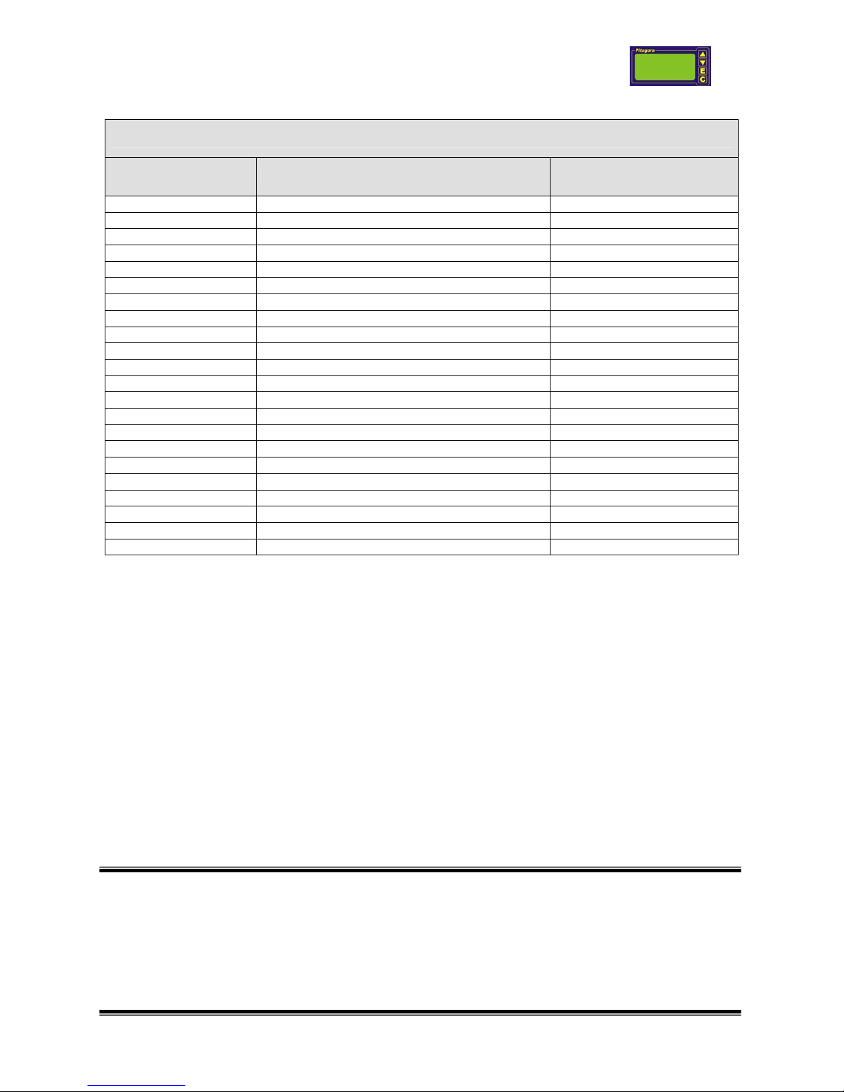
Terminal Description Notes DS Europe colour code
1
+ signal input from transducer
WHITE
2
- signal input from transducer
0 to ± 80 mV, differential
GREEN
5
- power supply to transducer BLACK
6
+ power supply to transducer
+ 5 Volts, use only power supply from
instrument to power transducers
RED
Terminals 3-4 are not connected
Terminal Description Notes DS Europe colour code
1
+ signal input from transducer
WHITE
2
- signal input from transducer
0 to ± 80 mV, differential
CH0 0 = Bridge 1
GREEN
3
+ signal input from transducer
WHITE
4
- signal input from transducer
0 to ± 80 mV, differential
CH0 1 = Bridge 2
GREEN
5
- power supply to transducer BLACK
6
+ power supply to transducer
+ 5 Volts, use only power supply from
instrument to power transducers.
RED
Terminal
Description Notes
DS Europe colour code
1
+ power supply to transducer
+ power supply for amplified transducer.
RED
2
+ signal input from transducer WHITE
3
- signal input from transducer
Example: ±10 V in put, maximum voltage
± 18 V
YELLOW or BLACK
6
- power supply to transducer
Between terminal 1 and 6 It is available
the power supply fed to the instrument (i.e.
+24 V)
YELLOW or BLACK
Terminals 4-5 are not connected
Terminal Description Notes DS Europe colour code
3
LOOP PLUS + power supply to transducer.
RED
6
LOOP MINUS
- power supply to transducer.
BLACK
Terminals 1-2-4-5 are not connected
Pitagora instruction manual V1 r 19 - 31/01/07
-9-
2.7 Connection of I10 single channel input card for Start-Stop digital signal
IMPORTANT NOTE: power supply fed to the magnetostrictive transducer is the same provided
to the instrument.
Power supply is to be:
• Not lower than 18 V, if connection cable to transducer is long no more than 20 mt.
• Not lower than 24 V, if connection cable to transducer is long no more than 100 mt.
• In case of longer distances, verify that at least 18 V are powering the connected
transducer.
Calibration and measuring functions of magnetostrictive transducers are like all other types of
transducers (load cells, pressure transducers etc.).
2.8 Connection of output cards O1 = 0-5 V and O2 = 0-10 V
2.9 Connection of output cards O3 = 4-20 mA and O4 = 0-20 mA
Note: under request this card can be supplied with optional voltage and current output, at the
same time, with the same setting.
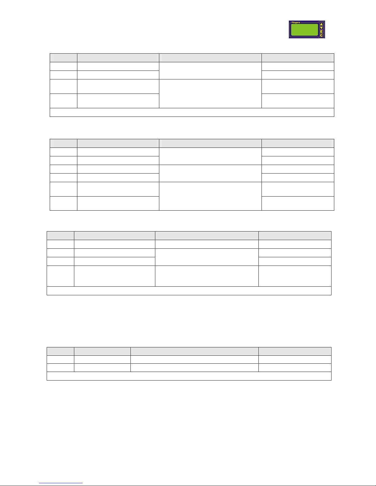
Terminal Description
Magnetostrictive transducer
DS Europe series PCX-ss
1 + RTX Brown
2 - RTX
SERIAL INPUT ( RS-422 )
Blue
3
- TXD Yellow
4
+ TXD
SERIAL INPUT ( RS-422 )
White
5 + 24 Volt ( + Power supply ) from external power
supply generator
Red
6
GND ( - Power supply ) Black
Terminal Description
1 Voltage analog output 0-5 Volt ( O1) 0-10 Volt ( O2 )
3 AGND Common for power supply and signal
Terminals 2-4-5-6 are not connected
Terminal Description
2 Current analog output 4-20 mA ( O3 ), 0-20 mA ( O4 )
3 AGND Common for power supply and signal
Terminals 1-4-5-6 are not connected
Pitagora instruction manual V1 r 19 - 31/01/07
-10-
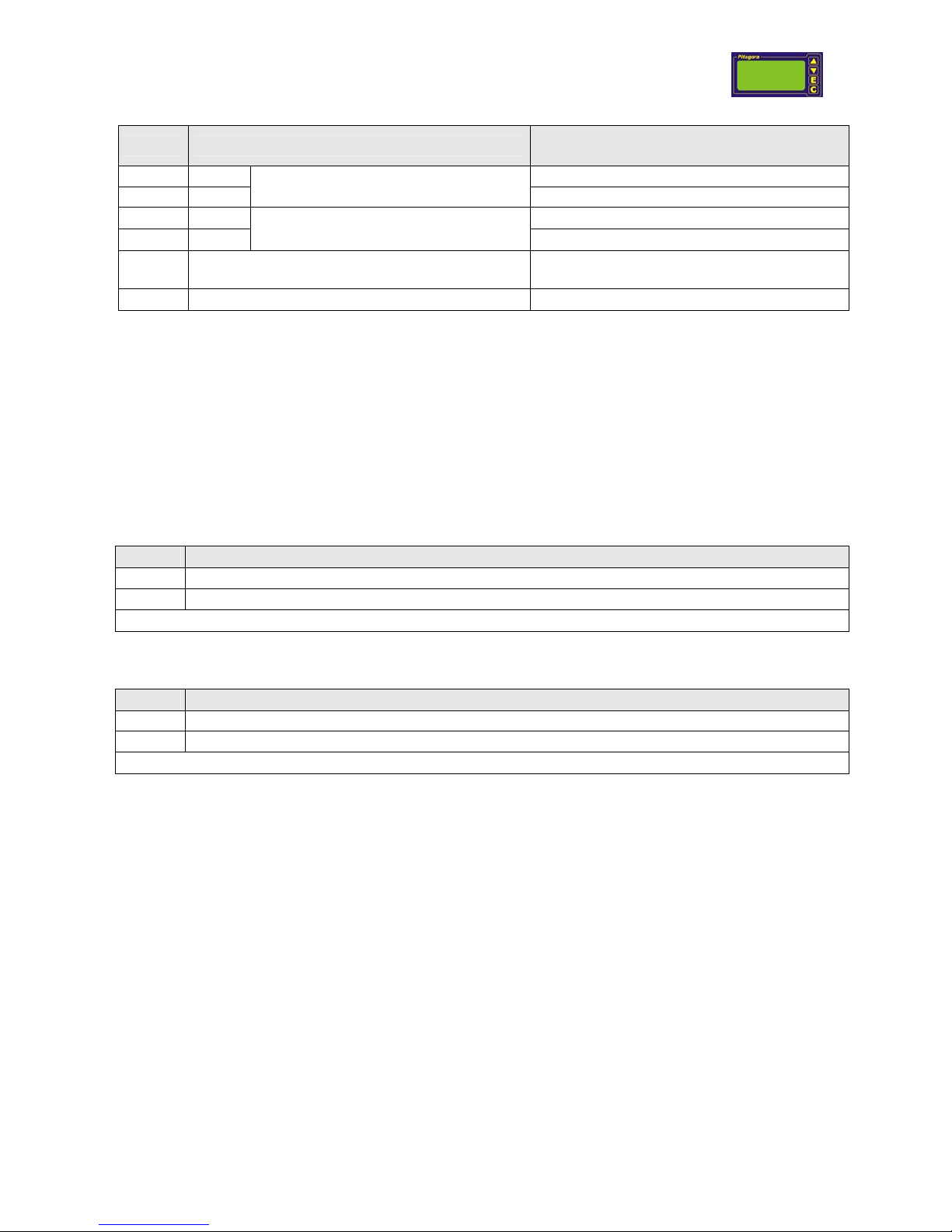
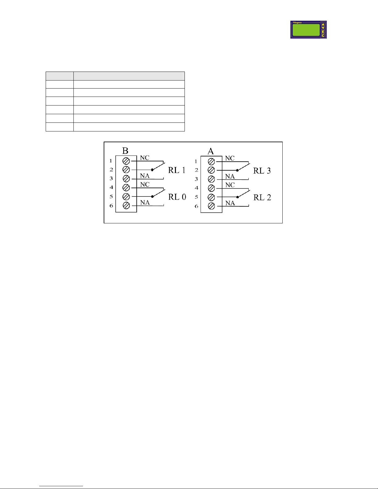
2.10 Connection of D0 card, two relays alarm level
Relays technical specifications:
- Maximum Vdc: 30 Vdc.
- Maximum current: 2 A.
- Maximum power: 1W.
- Switching time: 2 mS.
Fig. 10: Connections of D0 card, with 2 alarm levels.
Terminal Description
1 Relay 1 Normally Closed contact
2 Relay 1 Common contact
3
Relay 1 Normally Open contact
4
Relay 2 Normally Closed contact
5
Relay 2 Common contact
6
Relay 2 Normally Closed contact
Pitagora instruction manual V1 r 19 - 31/01/07
-11-
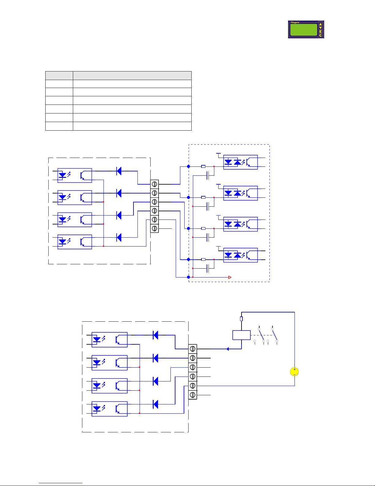
2.11 Connection of D1 card, four optically insulated alarm levels
Opto insulator technical features
- Maximum Vdc: 70 Vdc.
- Maximum current: 50 mA.
- Maximum power: 150 mW.
- Switching time: 18µSmax.
- Insulation: 3000 Vrms
Above figure shows the typical connection used for PLC “SINK” type connection.
It is to be considered that this is an “open collector” setting and that emitters are connected
together to terminal 5 of the instrument. Internal protection diodes are applied, for reverse
polarity protection.
1
2
3
4
5
6
Slot A o B
OUTPUT INTERFACE
AN 401 PLUS
RELAY- DPDT
I max 50 mA
V_Relè
External relays, connection to optically insulated outputs (same connection for the other 3).
Terminal Description
1 Optically insulated output 1 ( open collector)
2 Optically insulated output 2 ( open collector)
3
Optically insulated output 3 ( open collector))
4
Optically insulated output 4 ( open collector)
5
Emitter, common output
6
Not Connected
1
2
3
4
5
6
Slot A o B
OUTPUT INTERFACE
+24V
+24V
+24V
+24V
24V Com mon
TIPICAL PLC SINK CONNECTION
AN 401 P LUS
Pitagora instruction manual V1 r 19 - 31/01/07
-12-
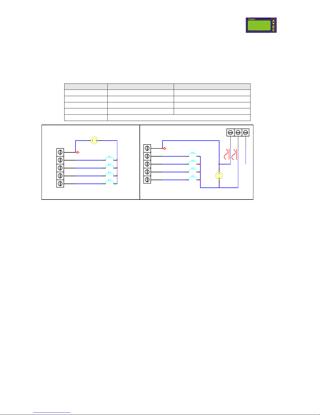
2.12 Connection of external contacts
Pitagora instrument has 4 optically insulated input contacts, whose functions are described in the
operating modes descriptions of this manual.
External contacts are on the terminal board labelled as “INPUT”.
Terminal Description
Notes
2 Input 1 ( KEY 1 ) +28 Volt maximum voltage
3 Input 2 ( KEY 2 ) +28 Volt maximum voltage
4 Input 3 ( KEY 3 ) +28 Volt maximum voltage
5 Input 4 ( KEY 4 ) +28 Volt maximum voltage
1 EXGND ( insulated voltage reference )
Fig. 1a: Insulated connection Fig. 1b: Not insulated connection.
Above figures (Fig.1a and Fig.1b ) show the connection for push buttons use (same for relays,
TTL, transistors etc.).
A voltage, between 12 and 28 Vdc, is to be fed in order to activate the opto-insulator LED’s.
Opto insulator main specifications:
• Insulation: 3000 Vrms
• Switching time: 18 µS ( max )
• Release time: 18 µS ( max )
2.13 Connection of grounding for CE regulation
In order to achieve best immunity in case of electrical noise, It is advisable to:
• Negative of power supply is to be grounded.
• Connect EARTH terminal to closer grounding in case Pitagora instrument is powered by
power supply generator that is separated from the other generators of the application.
• Analog outputs, RS232, RS485 etc of Pitagora are all grounded: be careful not to have
ground loops.
• It is advisable that all power supply negative (GND) connections are referred to the same
earth connection for the whole machinery.
• Electrical signal cables are not to be cabled together with power cables.
In case of low electrical noise environments this connection can be avoided.
1
2
3
4
5
INPUT
EXGND
KEY1
+24Vdc
1
2
3
1
2
3
4
5
INPUT
EXGND
+24Vdc
KEY2
KEY3
KEY4
KEY1
KEY2
KEY3
KEY4
EARTH
Pitagora instruction manual V1 r 19 - 31/01/07
-13-
2.14 Connection of RS232 serial port (COM1)
RS232 port can be used either for setting the instrument parameters and for getting Its measured values, in low electrical
noise environments, and It does not allow a digital communication with a cable longer than 3 m (the distance can be
optimized by modifying the baud rate).
Instrument Computer
TX ⎯⎯⎯⎯⎯⎯⎯⎯⎯⎯⎯⎯⎯⎯⎯⎯⎯> RX
RX <⎯⎯⎯⎯⎯⎯⎯⎯⎯⎯⎯⎯⎯⎯⎯⎯⎯ TX
GND ⎯⎯⎯⎯⎯⎯⎯⎯⎯⎯⎯⎯⎯⎯⎯⎯⎯ GND
Usual connections for RS232 communication, between Instrument and computer are (standard straight serial cable):
Pitagora - RS 232 Computer
9 pins female connector 9 pins connector 25 pins connector
TX 2 2 2
RX 3 3 3
GND 5 5 7
2.15 Connection of RS485 (RJ-11b connector) serial com port
RJ – 11b Cable colour Description DS Europe serial adapter Mod. 658-5-x
1
Brown Not connected
-
2 White Data + ( A ) 5
3 Red Data – ( B ) 4
4 Blue GND 1
Pitagora instruction manual V1 r 19 - 31/01/07
-14-
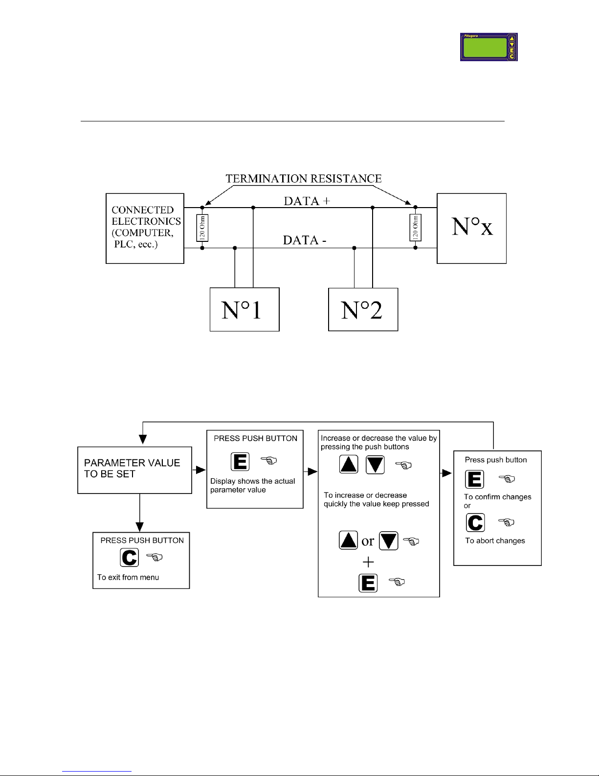
2.15.1 Terminator Resistances
MULTI-DROP connection (as RS485) requires to apply two terminator resistances (if not already applied): one
on the remote electronics (computer, PLC etc.) and one on the last connected Pitagora instrument
(Pitagora instrument are not supplied with internal terminator resistor but it can be applied, under request
).
The resistance is to be 120 Ohm, ¼ watt.
This resistance is to be applied only on the last connected instrument, in order not to lower too much the overall
line impedance (figure 11 ).
fig. 11 : Multi-drop connection of several instruments.
3 Menu setting – general sequence
This chapter describes the procedure to set instrument’s working parameters.
This sequence is valid for all the instrument’s menus.
▼ Down arrow: It allows to scroll all the possible choices of a menu or to decrease a
parameter’s value.
▲ Up arrow: It allows to scroll all the possible choices of a menu or to increase a
parameter’s value.
E Enter: It confirms modified parameter and stores the value on the instrument.
C ESC: It allows to exit from a menu without confirming any change to the parameter’s
value or to zero (dynamic zero) the value shown on display when Pitagora is in normal
working status.
Pitagora instruction manual V1 r 19 - 31/01/07
-15-
These push buttons can have additional functions, depending on the chosen operating modality.
Push button can be damaged, if sharp objects are applied (screwdrivers or similar).
By keeping pressed the E button, when modifying a parameter, allows to show on display (prior to the
button release) the numeric index corresponding to the parameter (i.e.: P03501). The index can be used
to modify the parameter by means of digital serial communication.
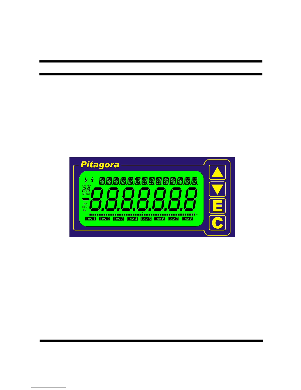
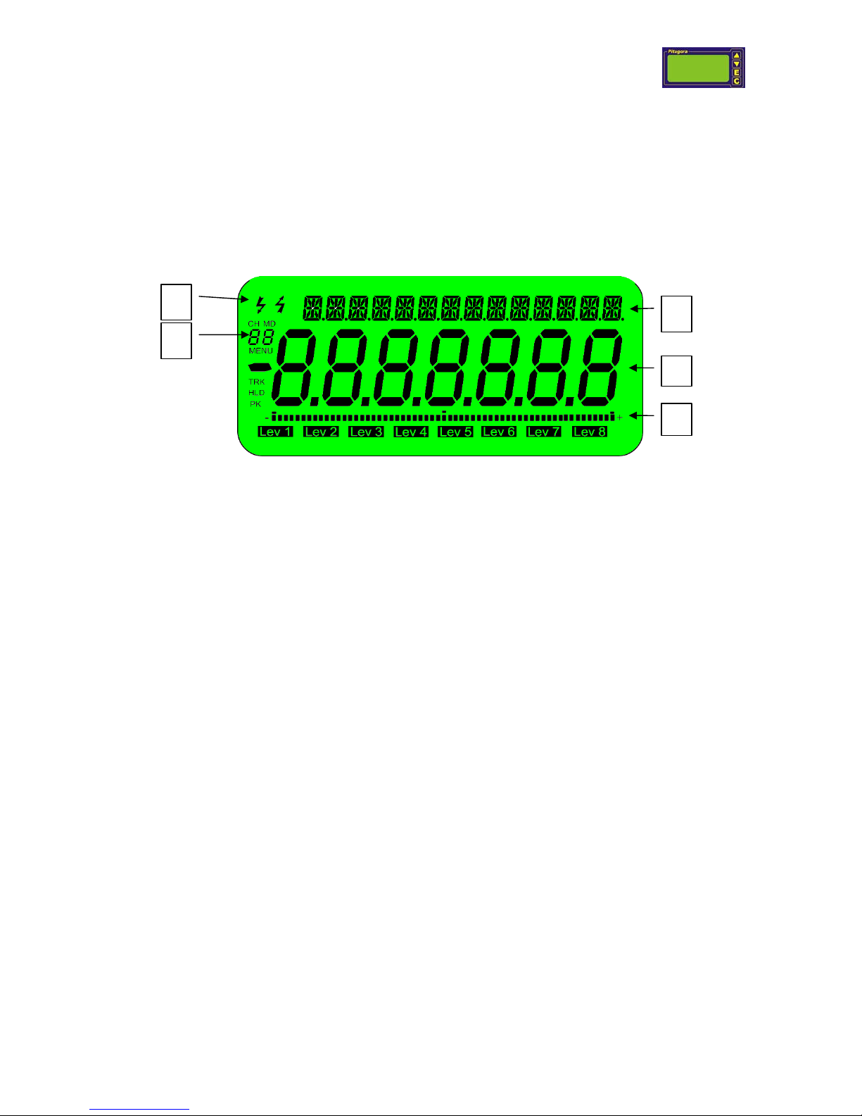
4 Display
Pitagora instrument is has an LCD display, with backlight, able to show the following data:
1. Main 7 alphanumeric digits display, 8 segments, plus polarity able to display numbers up to ±
9999999 or words (capital or small letters).
2. Secondary display, with 14 alphanumeric digits, used to show information referable to the
measured value displayed on the main displayed or used to provide additional indications
during instrument customization.
3. Bar display, with central zero, to display the behaviour of the measured value.
4. MENU indication, active when Pitagora instrument is used during Customization procedure
with a numeric value that indicates the active personalization level.
5. Serial communication and data transfer activity.
When Pitagora instrument is switched on it will show, in sequence, the following information:
1. Pitagora Name of instrument
2. Pt 401 Hardware version
3. V 1.00 Installed firmware version
4. SN. X Serial number of instrument
5. MD 1 Active measurement modality
4
2
3
5
1

Pitagora instruction manual V1 r 19 - 31/01/07
-16-
5 Instrument setting
Personalization menu is protected against unwanted accesses.
Switch on the instrument, keeping pressed at the same time ▲ and C push buttons.
Instrument will allow to setup the card eventually installed into slot A.
SLSET will confirm on the display that personalization menu is active (SLot SETup).
“MENU 1-” indicates that setup procedure for the chosen card is on the topmost level of the main
personalization menu.
When push button are released display shows on upper alphanumeric line the type of menu (SLOT
SETUP); main display line indicates the name of the installed card to be customized.
Firmware uses the following syntaxes, when setting card parameters:
1. Slot reference: a letter, followed by a decimal point, to indicate the reference position of the
card installed on the instrument (real card) or to indicate virtual card reference.
2. Function/parameter reference: 3 or more letters that identify the function/parameter to be set.
If an A/D card (mod. I4) is installed in slot C, setup menu will refer to It as C.AdC (C. to indicate
slot number = C; AdC to indicate card type = A/D converter); B.AdC indicates that an A/D card
is installed on slot B.
The following type of cards may be considered by Pitagora instrument:
• Real card: cards installed on slots from A to D, on the rear of the instrument.
• Virtual: are peripherals applied in the instrument, like serial communication ports or like
functions that allow to perform calculus, alarm levels that will activate relays outputs or will
send status messages through serial connection or complex functions like P.I.D or softP.L.C.
etc.
Menu structure, used to configure the Pitagora instrument, will be defined by the position and type of
active cards on the instrument.
Menu parameters can be set in the following ways:
Prefix Menu parameter
Card setting A letter, used to identify:
> the card slot, on the rear of the
instrument
> a virtual card
C. for slot number C
H. for virtual slot number H
Corresponding function or feature
LEV indicates the alarm levels.
Channel
setting
A number, to identify the channel of the
card (I/O cards with several
inputs/outputs)
Corresponding function or feature
VLO, to display the LO parameter.
Available sub menus, for each card, can be accessed by pressing E push button.
To return to the main menu from a sub menu, press C button.
Pitagora instruction manual V1 r 19 - 31/01/07
-17-
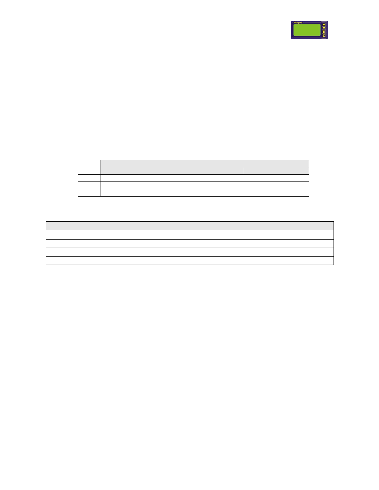
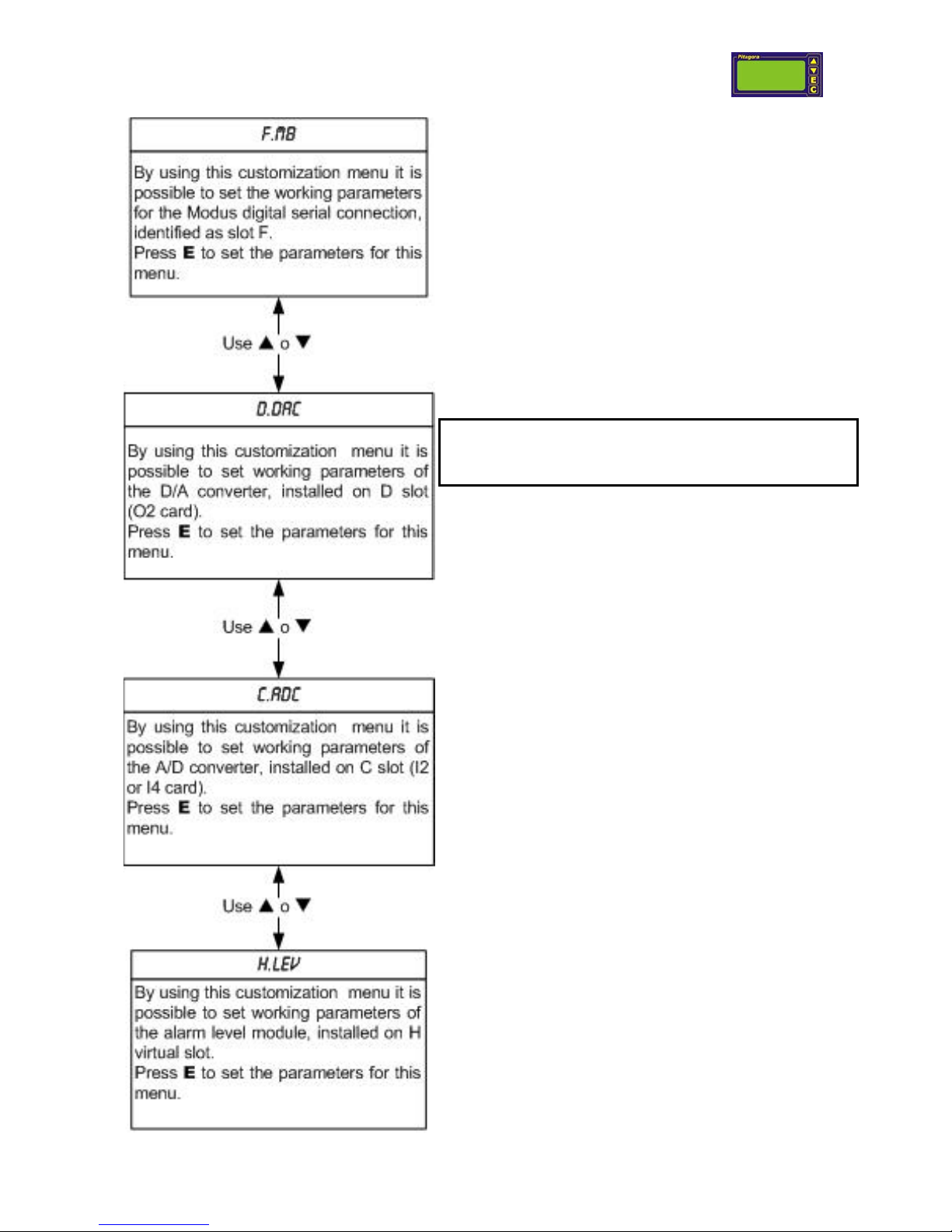
Example: menu structure of an instrument so
configured:
Slot A (physical) = mod. D0 or D1 relay card.
Slot B (physical) = empty.
Slot C (physical) = I1 or I4 input card, with A/D
converter.
Slot D (physical) = O2 analog output card.
Slot F (virtual) = Modbus digital output.
Slot H (virtual) = alarm level
By pressing C pushbutton Pitagora instrument exits
customization menu entering into normal measure
modality, after having saved parameter (SAVE is
displayed) and after a software reset.
Menu structure: this customization menu structure is
dynamic as It depends from the type and position of the
installed hardware cards and is supplied just as example.
NUL, with the reference of the selected slot, will be
shown (example: b.nul) if no physical card is installed
on the selected slot or if no virtual function is available.
 Loading...