

Page 1
V2.5 – Last Updated on 15/03/05 by Leon Kok – © Copyright 2005 – DSE (NZ) Ltd.
This manual describes firmware release 10 v1
XH1175
DSE ADSL Router UTP 4x LAN
USER MANUAL
Page 2

XH1175 - DSE ADSL Router
Life Support Application
This product is not designed for use in life support appliances, devices, or systems where
malfunction of the product can reasonably be expected to result in personal injury. Customers
using this product for use in such applications do so at their own risk and agree to fully
indemnify DSE (NZ) Ltd for any damages resulting from such improper use or sale.
About This Manual
This manual is designed to assist users in installing their new ADSL Router. Information in
this document has been carefully checked for accuracy; however, no guarantee is given as to
the correctness of the contents. The information contained in this document is subject to
change without notice.
Copyright
© Copyright 2004 DSE(NZ) Ltd - All rights reserved. No part of this publication may be
reproduced, stored in a retrieval system, or transmitted in any form or by any means
(electronic, mechanical, photocopying, recording, or otherwise), without the prior written
permission of the publisher.
Trademarks
Microsoft, Windows 98, Windows ME, Windows 2000 and Windows XP are registered
trademarks of Microsoft Corporation. Other trademarks and registered trademarks of products
referred to in this manual are the properties of their respective holders.
Compliance
• DSE XH1175 ADSL Router UTP 4x LAN – Telecom NZ Telepermit: PTC 272 / 04 / 037
PTC200 General Warning
• The grant of a Telepermit for any item of terminal equipment indicates only that
Telecom has accepted that the item complies with minimum conditions for connection
to its network. It indicates no endorsement of the product by Telecom, nor does it
provide any sort of warranty. Above all, it provides no assurance that any item will
work correctly in all respects with another item of Telepermitted equipment of a
different make or model, nor does it imply that any product is compatible with all of
Telecom's network services.
This DSE XH1175 ADSL Router UTP 4x LAN on Long Lines
•
This DSE XH1175 ADSL Router UTP 4x LAN may not achieve the type of “high
speed” operation expected when attached to a line that is longer than intended by the
ITU-T G992.1 ADSL standard i.e. >4 km of 0.4mm cable or a shorter cable length
with several tails or multiples. If the Router is installed in such conditions and does
not give the expected “download” performance, then do not refer the matter to the
Telecom Fault Service or ADSL Helpdesk.
The user should not modify or change this device without written approval of DSE (NZ) Ltd.
Modification could void authority to use this equipment.
1
Page 3

Table of Contents
1 Introduction.......................................................................................................................4
1.1
Package Contents...................................................................................................4
1.2
Minimum System Requirements .............................................................................4
2 Features ...........................................................................................................................5
2.1
ADSL Compliance...................................................................................................5
2.2
ATM Protocols and Encapsulations ........................................................................5
2.3
2.4
2.5
2.6
2.7
Hardware Installation ...............................................................................................................8
2.8
2.9
2.10 Power On................................................................................................................9
2.11 Make sure ADSL service is activated......................................................................9
2.12 Configure your phone equipment..........................................................................10
2.13 Connecting the Router to your PC ........................................................................12
2.14 Router / PC Connection Diagram..........................................................................12
3 Networking Settings........................................................................................................13
3.1
3.2
3.3
4 Configuring the ADSL Router..........................................................................................20
4.1
4.2
4.3
4.4
4.5
Bridge / Router Protocols........................................................................................5
Ethernet Interface ...................................................................................................6
HTTP Web-Based Management .............................................................................7
Quality-of-Service (QoS).........................................................................................7
Advanced Firewall...................................................................................................7
Front Panel .............................................................................................................8
Rear Panel..............................................................................................................8
2.12.1 Option 1: Install ADSL Filter(s) yourself............................................................10
2.12.2 Option 2: Have an ADSL splitter professionally installed ..................................11
TCP/IP Configuration for Windows 98...................................................................13
TCP/IP Configuration for Windows 2000...............................................................16
TCP/IP Configuration for Windows XP..................................................................18
Accessing the Web Manager ................................................................................20
Quick Setup ..........................................................................................................21
4.2.1 Automatic Setup ...............................................................................................21
4.2.2 Manual Setup ...................................................................................................21
4.2.3 Quick PPP Setup..............................................................................................22
4.2.4 Home................................................................................................................22
Basic.....................................................................................................................23
4.3.1 Home................................................................................................................23
4.3.2 PPP Status .......................................................................................................24
4.3.3 ADSL Status.....................................................................................................24
4.3.4 Diagnostic Test.................................................................................................25
4.3.5 System Log.......................................................................................................28
Advanced Configuration ...................................................................................29
4.4.1 WAN Configuration...........................................................................................29
4.4.2 LAN Configuration ............................................................................................33
4.4.3 PPP Configuration ............................................................................................35
4.4.4 NAT Configuration ............................................................................................37
4.4.5 DNS Configuration............................................................................................39
4.4.6 ADSL Configuration..........................................................................................40
4.4.7 Save Settings ...................................................................................................41
Advanced Status ..............................................................................................42
4.5.1 Home................................................................................................................42
4.5.2 System Log.......................................................................................................43
4.5.3 PPP Status .......................................................................................................43
4.5.4 ADSL Status.....................................................................................................44
4.5.5 WAN Status......................................................................................................45
2
Page 4

XH1175 - DSE ADSL Router
4.5.6 ATM Status.......................................................................................................45
4.5.7 Learned MAC Table..........................................................................................46
4.6
4.7
4.8
Support ..................................................................................................................................71
4.9
4.10 Xtra Settings & Support Details.............................................................................71
4.11 Contacting the DSE Support Team.......................................................................71
5 Warranty .........................................................................................................................71
6 Glossary of terms............................................................................................................72
7 Appendix.........................................................................................................................76
7.1
7.2
7.3
Advanced System Management.......................................................................47
4.6.1 Complete Status ...............................................................................................47
4.6.2 Diagnostic Test.................................................................................................47
4.6.3 System Log.......................................................................................................47
4.6.4 Reset to Defaults ..............................................................................................48
4.6.5 Local Firmware Upgrade ..................................................................................48
4.6.6 Password Configuration....................................................................................50
Advanced Advanced Features..........................................................................51
4.7.1 Virtual Server....................................................................................................51
4.7.2 Bridge Filtering .................................................................................................53
4.7.3 Miscellaneous Configuration.............................................................................54
4.7.4 Route Table......................................................................................................57
4.7.5 RIP Configuration .............................................................................................58
4.7.6 RIP per Interface Configuration ........................................................................59
Firewall .................................................................................................................60
4.8.1 Firewall .............................................................................................................60
4.8.2 Protection Policy...............................................................................................60
4.8.3 Firewall / Hacker Log........................................................................................62
4.8.4 Service Filtering................................................................................................62
4.8.5 IP Group ...........................................................................................................63
4.8.6 Service Group...................................................................................................64
4.8.7 Time Window....................................................................................................66
4.8.8 Inbound Policy ..................................................................................................67
4.8.9 Outbound Policy ...............................................................................................68
4.8.10 Inbound Policy Example ...................................................................................69
4.8.11 Outbound Policy Example.................................................................................70
Ihug Settings & Support Details ............................................................................71
Router Help...........................................................................................................76
DSE PC Online Store page...................................................................................77
Router Default Settings.........................................................................................78
3
Page 5

1 Introduction
The XH1175 ADSL Router is optimised to address the growing demand for high-speed
Internet access. With four IEEE 802.3-compliant Ethernet (UTP) ports, it aims to provide a
wide array of connectivity options without relaying on host PC drivers.
The ADSL Ethernet Router is an “always-on” high-speed broadband connection to the
Internet. Using existing twisted-pair telephone lines, ADSL technology provides data rates
more than 100 times as fast as a traditional analog modem, without an interruption in
telephone service.
The ADSL Ethernet Router is fully compliant with the full-rate ADSL (T1.413 Issue 2 and
G.dmt) and the splitterless G.lite (G.992.2) standards. It can achieve data transfer rates of up
to 8Mbps downstream and 1Mbps upstream.
1.1 Package Contents
Carefully unpack and remove the contents. If any of the following items are missing or
damaged, contact the Dick Smith Electronics store you purchased the device from.
• XH1175 DSE ADSL Router UTP 4x LAN
• 12V DC Adaptor (low-profile)
• RJ-11 (Telephone) Cable
• RJ-11 to BT Adaptor
• UTP Fast Ethernet Crossover Cable
• Installation CD
• User Manual
• Quick Start Guide
1.2 Minimum System Requirements
• Java-enabled Web Browser (e.g. Firefox / Internet Explorer / Opera)
• Ethernet Connection
• Any operating system or computer capable of 10/100Mbps, Simplex or Duplex
connection with support for TCP/IP.
• For Internet Services, ADSL is also required
4
Page 6

2 Features
2.1 ADSL Compliance
• ANSI T1.413 Issue 2
• ITU G.992.1 (G.DMT)
• ITU G.992.2 (G.Lite)
• ITU G.994.1 (G.hs)
• Annex A & Annex B
2.2 ATM Protocols and Encapsulations
• PPP over ATM VCMUX (RFC 2364)
• PPP over ATM LLCSNAP (RFC 2364)
• Bridged IP over ATM LLCSNAP (RFC 1483)
• Routed IP over ATM LLCSNAP (RFC 1483)
• Bridged IP over ATM VCMUX (RFC 1483)
• Routed IP over ATM VCMUX (RFC 1483)
• Classical IP over ATM (RFC 1577)
• PPP over Ethernet VCMUX (RFC 2516)
• PPP over Ethernet LLCSNAP (RFC 2516)
• 8 PVCs (simultaneous and encapsulation independent)
• VPI/VCI range 0-255, 0-65536
Encapsulation hunting of up to 8 pre-defined VPI/VCI & encapsulation sets
•
• AAL5 UBR & CBR
OAM F4/F5
•
XH1175 - DSE ADSL Router
Please note that at the time of printing, Telecom NZ only supports PPPoA (RFC2364).
Even though this router supports many other protocols, you will not be able to use them until
Telecom NZ supports them. If Telecom NZ decides to support a new protocol, we will
endeavour to post the correct settings for the router on our website http://adsl.dse.co.nz/.
2.3 Bridge / Router Protocols
• IEEE 802.1D (self learning transparent bridge)
128 MAC Address support
•
• Static IP routing (configurable route table)
• RIPv2 (backward compatible with RIPv1)
• DHCP server (configurable and supports up to 253 addresses)
• DHCP client
• DHCP relay agent
• PPP auto reconnect and configurable timeouts
• PPP auto reconnect on WAN access
5
Page 7

• 128 character support for PPPx username/passwords
• ALG support (MSN Messenger 4.x, H.323 (Microsoft NetMeeting), AOL Instant
Messenger, Windows Media Player, Real Audio, CuSeeMe 5.00, DirectX 8.0 –
DirectPlay, IPSec, PPTP VPN pass-through, L2TP VPN pass-through, HTTPS,
HTTP, FTP, ICMP, SMTP, POP3, NNTP, Telnet, Age of Empires 2, StarCraft,
Diablo (Blizzard), Quake 2/ Quake 2 Server, Quake 3, Doom, Half Life Counter
Strike/ Team Fortress Classic, Return to Castle Wolfenstein, Unreal Tournament,
EverQuest, Warcraft (Blizzard))
• Virtual server
• Port range mapping (as required by some online games)
• VPN pass through (IPSec - ESP Tunnel mode, L2TP, PPTP)
• Bridge filtering
• ICMP
• IGMP
• MAC Address Spoofing
• PPP Half Bridge
• Auto VPI/VCI PPPoE/PPPoA detection
• Multiple PPP sessions per PVC (While this router supports Multiple PPP sessions
per PVC, it will only work if Telecom NZ supports it. At the time of printing,
Telecom NZ didin’t support it)
2.4 Ethernet Interface
• IEEE 802.3 compliant
• 10/100Mbps – Full duplex support
• Each port can work at 10 Mbps or 100Mbps, full-duplex or half-duplex mode
• Automatic MDI/MDIX crossover for 100Base-TX and 10Base-T ports
• Auto-negotiation and speed-auto-sensing support
• Back-pressure-based flow control on half-duplex ports
• Pause-frame-based flow control on full duplex ports
• Store-and-forward switching mode
• High performance lookup engine with support for up to 4096 MAC address entries
with automatic learning and aging
• Quality-of-Service (QoS) – 3 modes of operation
6
Page 8

XH1175 - DSE ADSL Router
2.5 HTTP Web-Based Management
• HTTP server
• Password protection (2 levels: User / Admin)
• Configurable Web pages
• FTP server
• Local firmware upgrade via FTP, HTTP or USB with DOS (depending on firmware
version)
• Remote firmware upgrade via FTP client (depending on firmware version)
• Configuration of LAN, WAN, and ADSL
• Restore to Factory defaults via Web or Hardware
• 7 layer diagnostics with links to help pages
• System logging
• Inner pair / Outer pair / Auto-detection of RJ-11
• IEEE 802.3
• 10/100 Mbps
2.6 Quality-of-Service (QoS)
The DSE ADSL Router supports several types of (Quality-of-Service) QoS functions with twolevel priority queues to improve multimedia or real-time networking applications. The QoS
functions are based on:
• Port-based priority
• 802.1Q VLAN priority tag
• The TOS / DS (DiffServ) field of TCP/IP as defined in RFC 2474
2.7 Advanced Firewall
The DSE ADSL Router incorporates an advanced, Stateful-Packet-Inspection (SPI) Firewall.
This firewall allows you to block / allow traffic according to Access Control Lists (ACLs) that
you have defined. This granular control of traffic, coupled with accurate logging, helps to
protect your network from Internet threats.
The Firewall is
configuration is needed. If your computer is “port scanned”, it will not answer – fooling the
scanner into thinking there is no device present.
enabled
by default, and will block all un-requested traffic – No user
7
Page 9
Hardware Installation
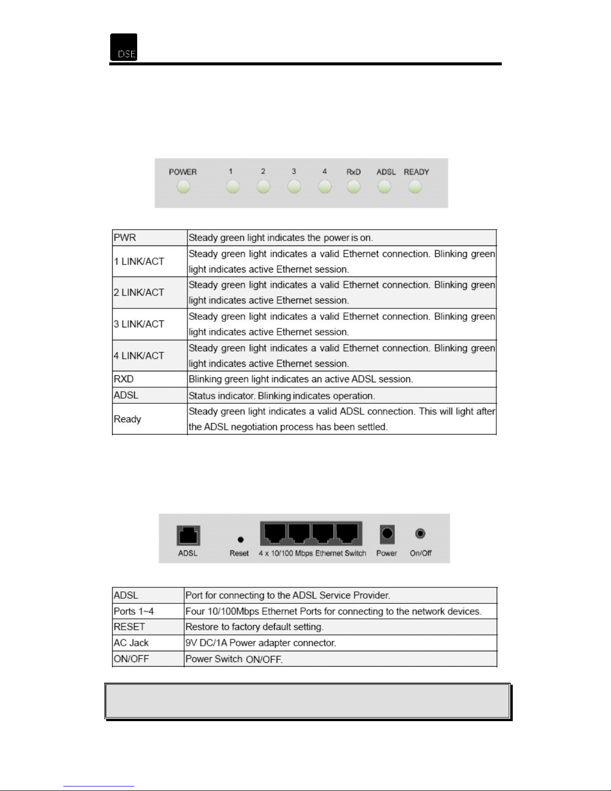
2.8 Front Panel
Operation of the LED indicators, as shown in the figure, are described below.
2.9 Rear Panel
The rear panel of the Router provides access to one WAN connection, the FACTORY RESET
button, four LAN connections, DC power input and the power ON/OFF switch as indicated in
the figure below.
To reset the router back to it’s default configuration setting, with the router on, hold
Note:
down the reset button for approximately 10 seconds. The router will then automatically restart.
8
Page 10

XH1175 - DSE ADSL Router
2.10 Power On
Connect the supplied 12V DC power adapter to a power outlet and turn the power switch,
located on the rear of the router, ON – the ADSL router will then enter a self-test phase.
When it is in the self-test phase, the READY LED will be lit ON for about 8 seconds - the
READY LED will then flash to indicate that the self-test phase has finished. Finally, the
READY LED will begin to flash constantly to indicate that the router is in normal operation.
2.11 Make sure ADSL service is activated
Before you can use your ADSL router to connect to the Internet, you must confirm that the
following conditions have been met.
• You are located within about 5km of an ADSL enabled phone exchange and you can get
Telecom’s ADSL service. This can be checked on-line by visiting “http://adsl.dse.co.nz”
and clicking on the link “
• Telecom has enabled the ADSL service to your house or office. This can be facilitated by
Ihug, Xtra or directly with Telecom
• Because ADSL and voice works on the same phone line at the same time, you need to
install ADSL filter/s on each of your normal Telephone devices or contact Telecom on 123
to arrange for someone to install a central splitter.
• You need to have an account with an Internet Service Provider (ISP) to enable your new
ADSL line to connect to the Internet.
• To connect with IHUG, simply call 0800 GET IHUG or visit www.ihug.co.nz/dse/adsl
To connect with XTRA JetStream, simply call 0800 JET XTRA
your area
” – or by calling Telecom on 0800 253 878.
9
Page 11
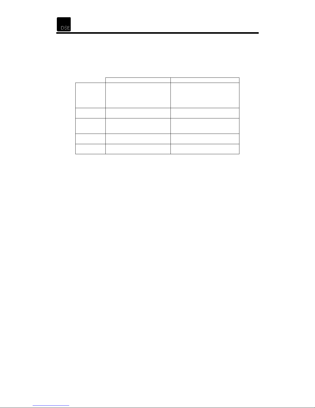
2.12 Configure your phone equipment
ADSL works by combining both voice and data signals on the same phone line. At your
premises, these signals need to be separated through the use of an approved Filter or
Splitter. Whilst both achieve the same results, each has their pros and cons.
Filter Splitter
Ideal for
Installation
method
Maximum
phones
How to get Dick Smith Electronics –
Cost
2.12.1 Option 1: Install ADSL Filter(s) yourself
Smaller installations with a
limited amount of phone
outlets (phones, answering
machines, cordless phones,
56K modems, Fax, etc.)
Self install Professional contractor only
5 – although double and triple
adaptors can be plugged into
the phone socket of each filter.
XH7556
Low per unit for most
installations
Larger installations or situations
where filters cannot be used
(alarm dialers and other
permanently wired telephone
devices).
Unlimited
Call Telecom on 123
Higher – depends on installer
and the actual installation
• All telephone equipment must be filtered in an ADSL installation. This includes corded
& cordless phones, answering machines, faxes, caller display units, analogue modem
(including such devices as a Sky digital decoder with integrated modem), dedicated
dialers, Etc. Filtering telephone equipment is as simple as plugging the XH7556 DSE
ADSL filter in-line with the device/s.
• Your ADSL modem or router will be the only device that can connect directly to your
jack point. However should an adaptor be required between the plug on the modem
cord and the jack point, or you wish to connect telephone equipment to the same jack
point, the DSE ADSL filter can be used by plugging the router or modem into the
“ADSL” socket.
• Do not plug an ADSL modem or router into the “PHONE” socket if the modem cord
has this type of plug.
It is important that the filter is connected the right way around.
•
The lead coming out of the side marked
“LINE”
is plugged into the telephone JP
Non-ADSL telephone equipment then plugs into the “PHONE” socket on the filter
The ADSL Modem or Router plugs into the “ADSL” socket on the filter.
Up to 5 filters can be used on a single telephone line. If you need to install more than
•
5 filters, a central splitter must be installed by Telecom.
• If you need to connect more than one item of telephone equipment at the same jack
point, then a double adaptor can be plugged into the “PHONE” socket of this filter.
• This Line Filter has a RJ11 “ADSL” socket incorporated. Only ADSL modems or
routers may be plugged into this socket.
10
Page 12
XH1175 - DSE ADSL Router
CAUTION:
the data link whenever a call is made or answered. In many cases the link will also be lost
when a call is received, even if it is not answered.
Failure to connect ALL telephone type equipment via a filter will result in loss of
2.12.2 Option 2: Have an ADSL splitter professionally installed
• Contact Telecom on 123 to arrange for a central splitter to be installed.
11
Page 13
2.13 Connecting the Router to your PC
1. You must have an Ethernet network card or adaptor installed (See appendix for a list of
compatible Ethernet Adaptors for PDA, Notebook or PC)
2. You must have the
3. Set your TCP/IP properties to “Obtain IP address automatically” – refer to the next
section of this manual on how to do this.
4. Once you have confirmed the above, proceed to the “
section of this manual.
TCP/IP protocol
installed.
Configuring the ADSL Router
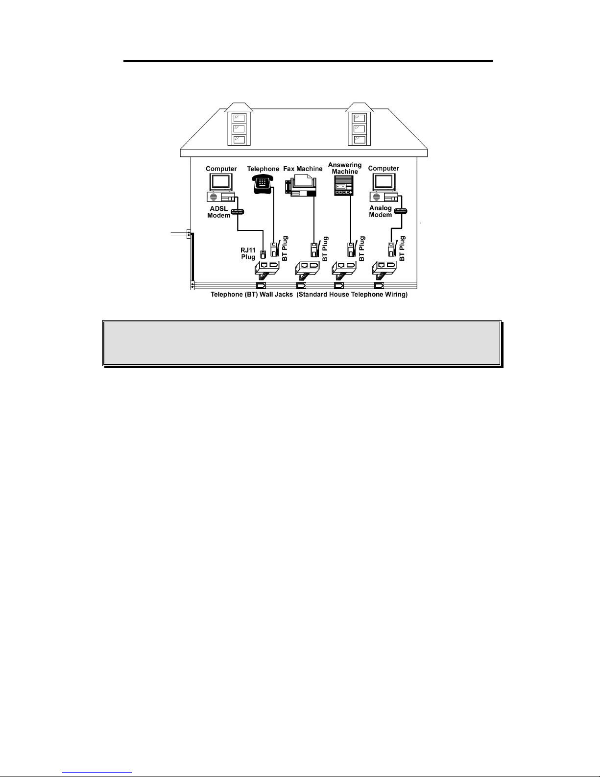
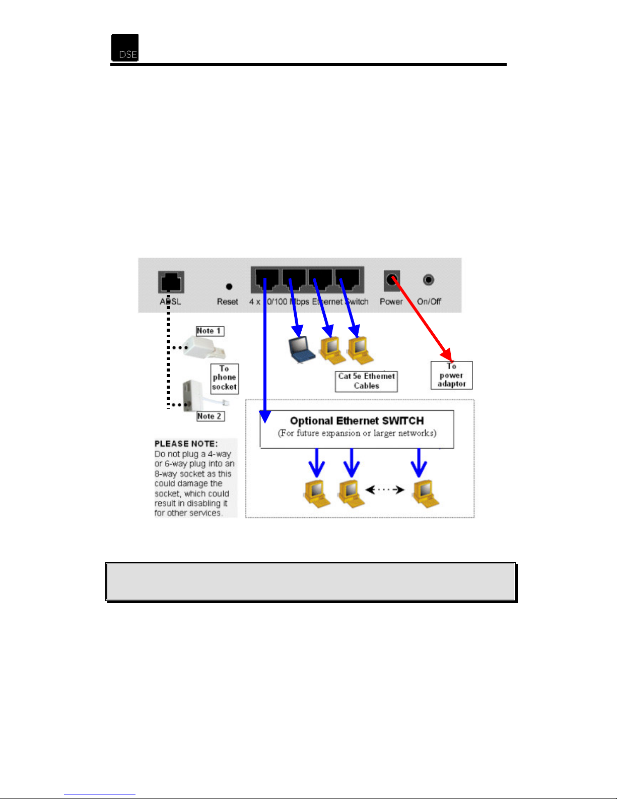
2.14 Router / PC Connection Diagram
Connect the router as shown in the diagram below. Please note that you do not need to have
as many computers as shown.
”
Note 1: Use this adaptor only if a SPLITTER has been installed
Note 2:
This is the correct way to install a XH7556 FILTER – refer to the filter instructions.
12
Page 14
XH1175 - DSE ADSL Router
3 Networking Settings
3.1 TCP/IP Configuration for Windows 98
Use the following steps to configure the manager PC to be a DHCP client. These same steps
must be performed for every host PC on your network if you use the DHCP function of the
Router.
1. Click the Start button and choose Settings and then Control Panel.
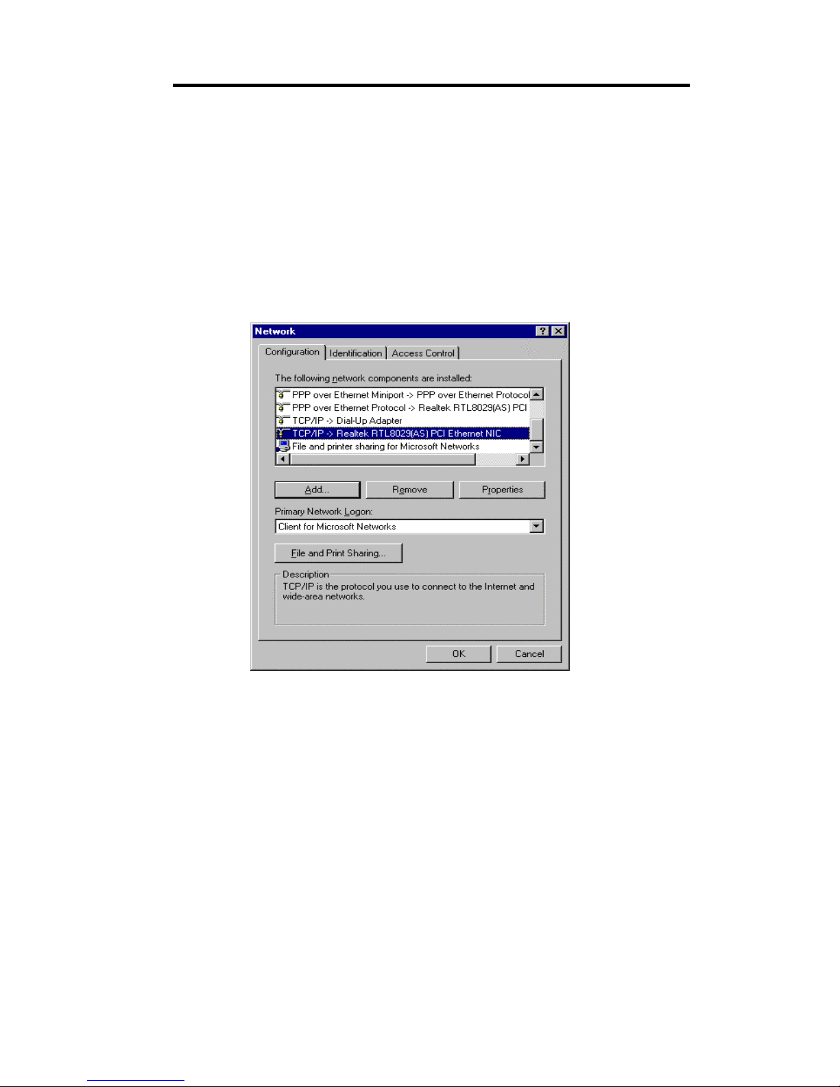
2. Double click the Network icon and select the Configuration tab.
3. Select the
TCP/IP
line in the Configuration tab and click
Properties
.
13
Page 15
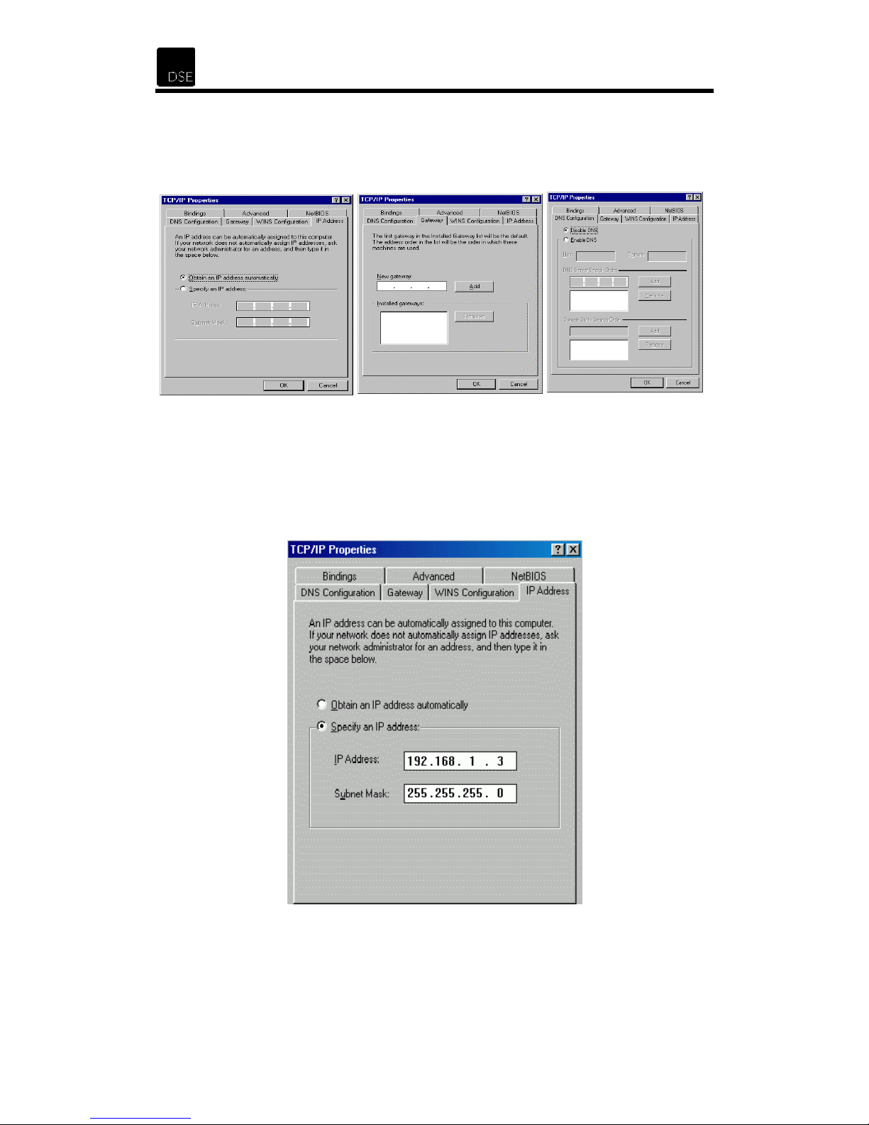
4. You have two setting methods:
A. Get an IP address from the Router (DHCP) – Make sure that you have the same
settings as shown in the following 3 screens. You will need to check the DNS
Configuration, Gateway, and IP Address tabs.
B. Configure IP Manually – See steps below.
Select
Specify an IP address
on the
IP Address
tab. The default IP address of the
Router is 192.168.1.2. So please use 192.168.1.X (where X is between 1 and 253,
except 2) for the IP Address field and 255.255.255.0 for the Subnet Mask field.
14
Page 16
XH1175 - DSE ADSL Router
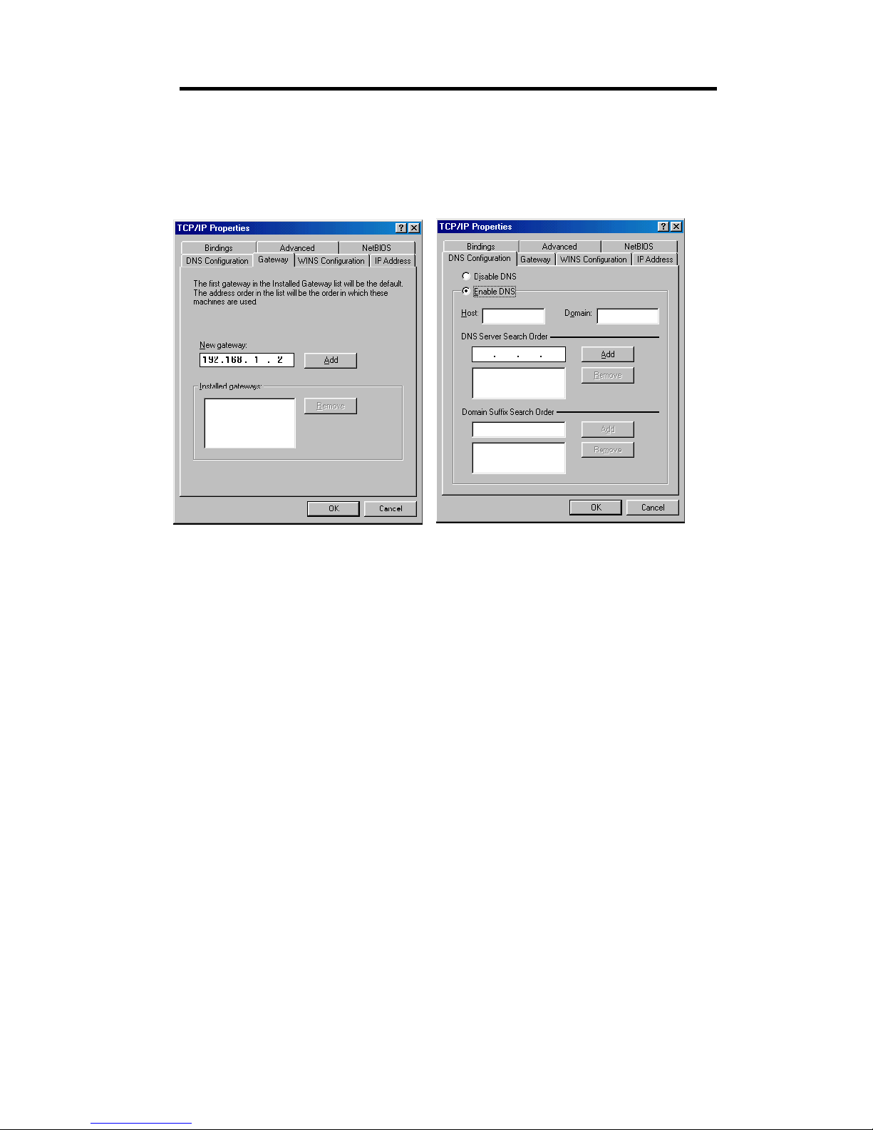
In the
Gateway
the New gateway field and click the Add button.
In the DNS Configuration tab, add the DNS values as provided by your ISP into the
DNS Server Search Order
tab, add the IP address of the Router (default IP is 192.168.1.2) in
field and click the
Add
button.
15
Page 17
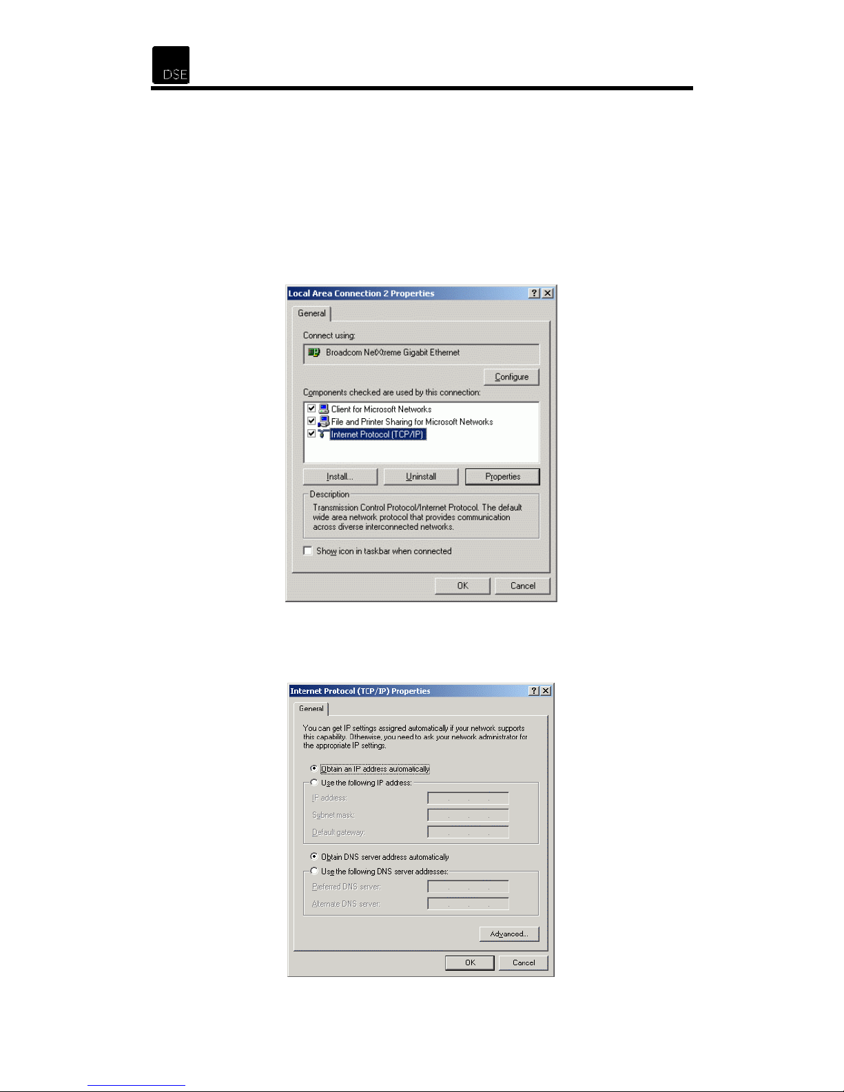
3.2 TCP/IP Configuration for Windows 2000
Use the following steps to configure the manager PC to be a DHCP client. These same steps
must be performed for every host PC on your network if you use the DHCP function of the
Router.
1. Click the Start button and choose Settings and then Control Panel.
2. Double click the Network and Dial-up Connections icon.
3. Right-click on your network connection and select
Select the
TCP/IP
line and click
Properties
.
Properties
from the drop down menu.
4. You have two setting methods:
A. Get an IP address from the Router (DHCP) – Make sure that you have the same
settings as shown in the following screen.
16
Page 18
XH1175 - DSE ADSL Router
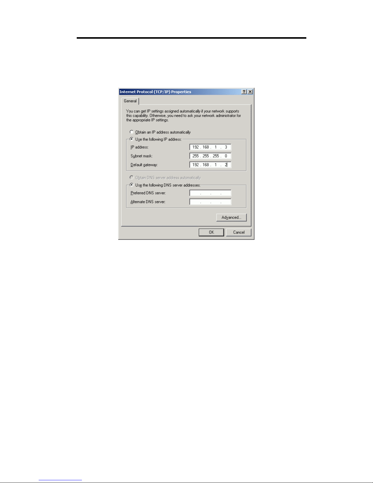
B. Configure IP Manually – Select
address of the Router is 192.168.1.2. So please use 192.168.1.X (where X is
between 1 and 253, except 2) for the IP Address field, 255.255.255.0 for the
Subnet Mask
Enter the DNS values as provided by your ISP.
field and 192.168.1.2 for the
Use the following IP address
Default Gateway
. The default IP
field as shown below.
17
Page 19
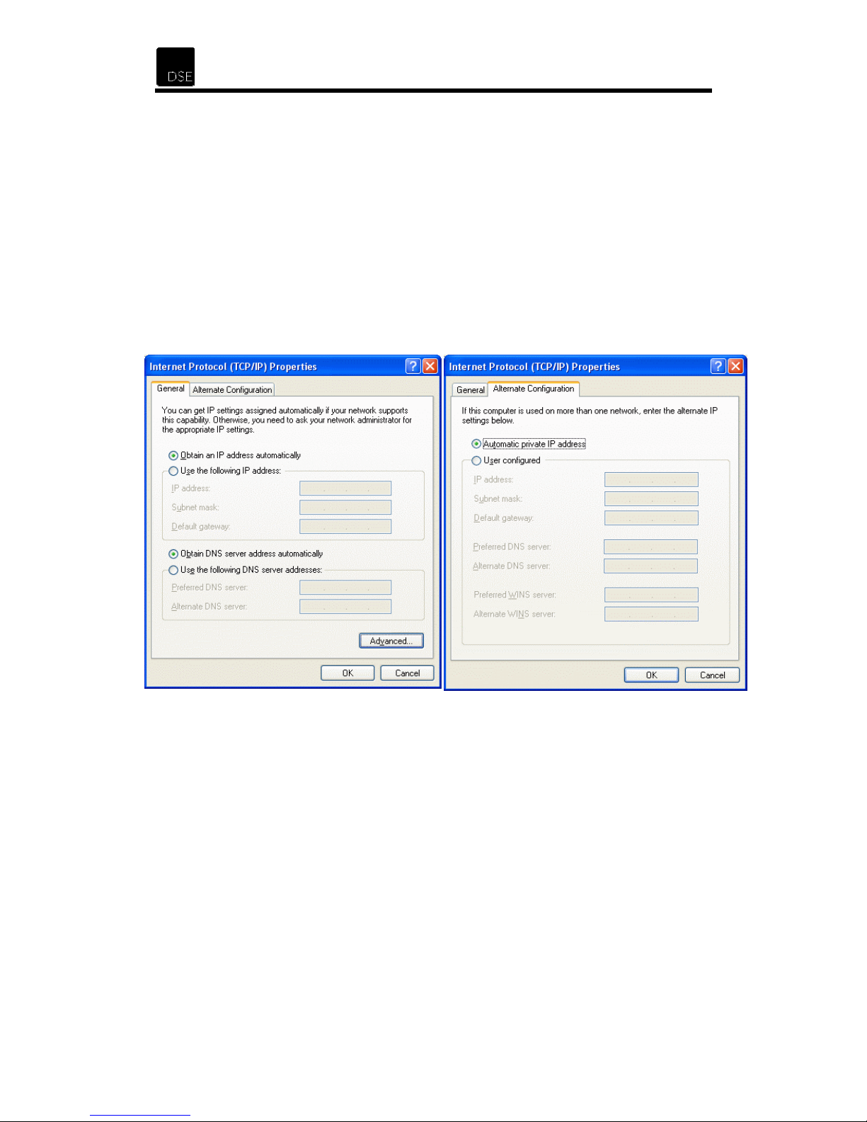
3.3 TCP/IP Configuration for Windows XP
Use the following steps to configure the manager PC to be a DHCP client. These same steps
must be performed for every host PC on your network if you use the DHCP function of the
Router.
1. Click the Start button and choose Settings and then Control Panel.
2. Double click the Network Connections icon.
3. Right-click on your network connection and select
menu. On the
4. You have two setting methods:
A. Get an IP address from the Router (DHCP) – Make sure that you have the
same settings as shown in the following 2 screens.
General
tab, select the
TCP/IP
Properties
line and click
from the drop down
Properties
.
18
Page 20
XH1175 - DSE ADSL Router
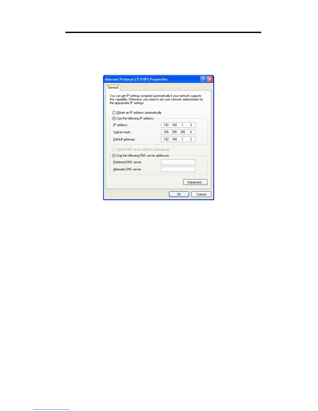
B. Configure IP Manually – Select
address of the Router is 192.168.1.2. So please use 192.168.1.X (where X is
between 1 and 253, except 2) for the IP Address field, 255.255.255.0 for the Subnet
field and 192.168.1.2 for the
Mask
DNS values which are provided by your ISP.
Use the following IP address
Default Gateway
field as shown below. Enter the
. The default IP
After configuring the TCP/IP protocol, you can use the ping command to check if your
computer has successfully connected to this router.
At a DOS prompt, execute the
Ping 192.168.1.2
If the following messages appear:
Pinging 192.168.1.2 with 32 bytes of data:
Reply from 192.168.1.2: bytes=32 time=2ms TTL=64
Reply from 192.168.1.2: bytes=32 time<10ms TTL=64
Reply from 192.168.1.2: bytes=32 time<10ms TTL=64
Reply from 192.168.1.2: bytes=32 time<10ms TTL=64
A communication link between your computer and this Router has been successfully
established. Please note that the values for bytes, time and TTL are not critical – we are
looking for a response. Otherwise, if you get the following messages:
Pinging 192.168.1.2 with 32 bytes of data:
Request timed out.
Request timed out.
Request timed out.
ping
command.
There must be something wrong in the configuration or it may be a cable issue. Please check
that the front panel LINK LED that corresponds to the port you have plugged in to is lit. Check
the TCP/IP configuration of your computer. Try turning off the router and restarting it. Then
reboot your computer.
19
Page 21
4 Configuring the ADSL Router
The Router offers a web-based (HTML) graphical user interface allowing users to manage the
Router using standard browser software such as Mozilla Firefox or Microsoft Internet
Explorer.
At the top of most HTML pages, you can click on a link that will open the help page relevant to
the page you are currently viewing.
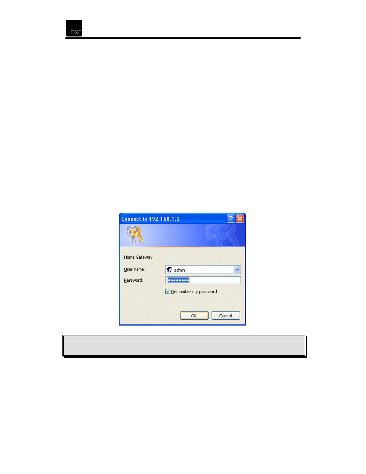
4.1 Accessing the Web Manager
1. Launch your Web browser.
2. Enter the LAN port default IP address http://192.168.1.2/
3. You will be prompted to enter a username and password.
Enter the default login User Name and Password as indicated below.
The default login username of the administrator is admin,
and the default login password is password.
The default login username for the non-administrator is
and the default login password is password.
Note: We strongly recommend that you change the default passwords. Failure to change the
default passwords could lead to unauthorised access to your router, network or computer.
user
,
20
Page 22
XH1175 - DSE ADSL Router
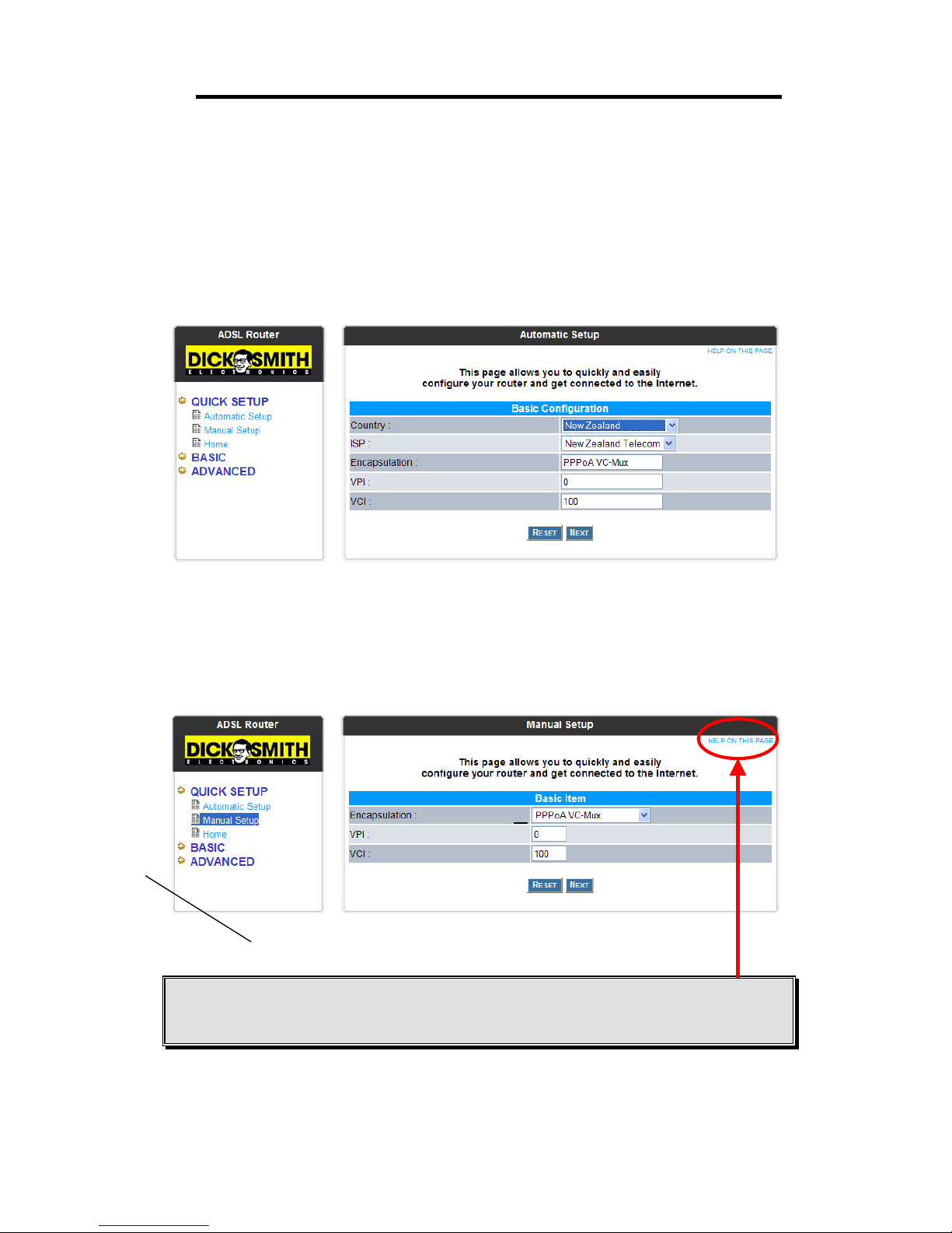
4.2 Quick Setup
The links under the Quick Setup heading are associated to the pages that allow you to
quickly configure your router and connect to the Internet.
4.2.1 Automatic Setup
The Automatic Setup allows you to quickly and easily configure your router. Simply select
New Zealand from the drop-down country list and click Next.
4.2.2 Manual Setup
The Manual Setup allows you to quickly and easily configure your router. Simply select the
type of
Note:
clicking on the link on the top right hand side corner. The help page contains information
relevant to the management page you were viewing.
Encapsulation
On each page of the web management interface, you can access a help page by
used,
VPI
and
settings, then click
VCI
Next
.
21
Page 23
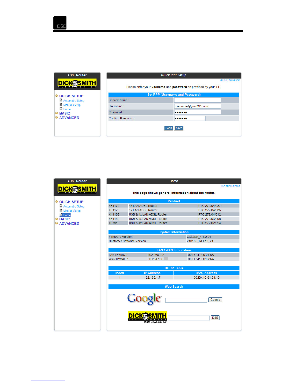
4.2.3 Quick PPP Setup
The Quick PPP Setup page allows you to enter your "Username" and "Password" - these
details are provided by your Internet Service Provider (ISP). Once entered, please click Save
and the router will save these settings and restart.
4.2.4 Home
The
interface status. You can even start a search with the Google search engine or search the
DSE website.
page shows general information about the router as well as the WAN and LAN
Home
22
Page 24

XH1175 - DSE ADSL Router
4.3 Basic
The links under the Basic heading are associated to the pages that allow you to check the
basic settings and current state of your router.
4.3.1 Home
The Home page shows general information about the router as well as the WAN and LAN
interface status. You can even start a search with the Google search engine or search the
DSE website.
23
Page 25

4.3.2 PPP Status
The PPP Status page shows the status of all PPP sessions.
These fields display the Connection Name (user defined), Interface (PVC), Mode
PPP:
(PPPoA), Status (Connected or Not Connected), Packets Sent, Packets Received, Bytes
Sent and Byte Received.
Connect and Disconnect:
connection for each PVC interface. Each PPP session can be connected and disconnected
individually using this page.
This field allows users to manually connect/disconnect the PPP
4.3.3 ADSL Status
The
ADSL Status
page shows the ADSL physical layer status.
The page shows the showtime firmware version, line state, modulation used, annex mode,
number of startup attempts, maximum transmission power, CO vendor, elapsed time, signal
to noise ratio margin, line attenuation, errored seconds, loss of signal, loss of frame, CRC
errors, data rate and the latency.
24
Page 26

XH1175 - DSE ADSL Router
4.3.4 Diagnostic Test
This page tests the connectivity of the physical and protocol layers for both LAN and WAN
connections.
ATM OAM F5 End to End Loop Back
• This test sends ATM OAM F5 End to End loop back request cells to the central office
equipments through your DSL connection.
This test return "PASS" if a response cell is received. Your service provider may not
•
support this test, your DSL modem could still work even if this test fails.
• If this test returns "FAIL" consistently and your DSL modem appears not to be
working, check to make sure the VPI and VCI are configured correctly.
• This test returns "SKIPPED" if the DSL synchronization test failed.
ATM OAM F5 Segment Loop Back
• This test sends ATM OAM F5 Segment loop back request cells to the central office
equipments through your DSL connection.
This test return "PASS" if a response cell is received. Your service provider may not
•
support this test, your DSL modem could still work even if this test fails.
• If this test returns "FAIL" consistently and your DSL modem appears not to be
working, check to make sure the VPI and VCI are configured correctly.
• This test returns "SKIPPED" if the DSL synchronization test failed.
25
Page 27

Check DSL Synchronization
• This test checks your DSL modem to see if it can successfully negotiate and establish
a DSL connection with your service provider.
• The test returns "PASS" if a DSL connection is established.
• If this test returns "FAIL", please try the test again in a few minutes. Your DSL
modem needs a few minutes to establish the DSL connection depending on your
phone line quality. Make sure your phone line is connected to your DSL modem and
check with your service provider to see if your service is activated.
• If this test returns "FAIL", all other tests will be skipped.
Check AAL5 Connection
• This test checks if the ATM AAL5 module is loaded correctly by your DSL router.
• This test returns "PASS" if the ATM AAL5 module is loaded correctly.
• If this test returns "FAIL", an internal error has occurred - there may be a problem
with your DSL router.
• This test returns "SKIPPED" if the DSL synchronization Test does not return "PASS".
Check PPP Connection
• This test checks if your username and password are correct.
• This test returns "PASS" if your login name and password have passed
authentication with your service provider.
• If this test returns "FAIL", run this test again in a few minutes. If this test consistently
fails, make sure that your login name and password are correct - Please recall that
the login name and password are case sensitive.
• This test returns "SKIPPED" if the PPPPoE Connection Test does not return "PASS"
(and your DSL modem is configured as PPPoE encapsulation).
• This test returns "SKIPPED" if the AAL5 Connection Test does not return "PASS"
(and your DSL modem is configured for PPPoA encapsulation).
Check PPPoE Connection
• This test checks if the PPPoE server can be located. This test is bypassed when not
in PPPoE mode.
• This test returns "PASS" if your DSL modem can see the PPPoE server.
• If this test returns "FAIL", run this test again in a few minutes. If this test consistently
return "FAIL", make sure that the PPPoE settings are in the correct configuration as
instructed by your service provider. Make sure that the VPI and the VCI of the current
VC settings and your service name are configured correctly. Note that your service
name is case sensitive.
This test returns "SKIPPED" if the AAL5 Connection Test does not return "PASS".
•
Check IP Assignment
• This test checks if you have been assigned a valid IP address by your service
provider (DHCP or static assignment).
• This test returns "PASS" if your DSL modem has been assigned a valid IP address by
your service provider.
• If this test returns "FAIL", run this test again in a few minutes after this test is
completed. If this test returns "FAIL" consistently and DHCP client is enabled on your
DSL modem, check with your service provider. If this test returns "FAIL" consistently
and your DSL modem is statically assigned an IP address, make sure the IP address
is the correct one assigned by your service provider.
This test returns "SKIPPED" if the AAL5 Connection Test does not return "PASS".
•
26
Page 28

XH1175 - DSE ADSL Router
Ping Gateway
• This test checks if your gateway can be reached through a ping (ICMP) request.
• This test returns "PASS" if the gateway can be reached through a ping request. The
• If this test returns "FAIL", run this test again in a few minutes. If this test returns
• This test returns "SKIPPED" if the IP Assignment Test does not return "PASS".
Ping Host
• This test checks if a host specified by your ISP can be reached through a ping (ICMP)
• This test returns "PASS" if the host specified by your ISP can be reached through a
• If this test returns "FAIL", run this test again in a few minutes. If this test returns
• This test returns "SKIPPED" if an IP address cannot be resolved.
Ping Primary Domain Name Server
gateway is assigned by your service provider, or obtained from your service provider
by PPP or DHCP negotiation.
"FAIL" consistently and your DSL modem appears not to be working, check to make
sure your statically assigned IP address is configured correctly or the DHCP client is
enabled on with the current VC.
request.
ping request.
"FAIL" consistently and your DSL modem appears not to be working, check to make
sure your statically assigned IP address is configured correctly or the DHCP client is
enabled on with the current VC.
• This test checks if your primary DNS can be reached through a ping (ICMP) request.
• This test returns "PASS" if the primary DNS can be reached through a ping request.
The primary DNS is assigned by your service provider or obtained from your service
provider by PPP or DHCP negotiation.
• If this test returns "FAIL", run this test again in a few minutes. If this test returns
"FAIL" consistently, check to make sure your statically assigned primary DNS IP
address is configured correctly or DHCP client is enabled with the current VC.
• This test returns "N/A" if there is no DNS configured.
Query Domain Name Server
• This test checks if a hostname (www.google.com) can be resolved to an IP address
though your Domain Name Servers.
• This test returns "PASS" if the host name can be resolved to an IP address.
• This test returns "FAIL" if the host name can not be resolved. If this test returns
"FAIL", run this test again in a few minutes. If this test returns "FAIL" consistently,
contact your service provider for further information.
27
Page 29

4.3.5 System Log
The System Log page shows the events triggered by the system. You can save a copy of the
current system log by clicking the link provided at the bottom.
28
Page 30

XH1175 - DSE ADSL Router
4.4 Advanced
The links under the Advanced Configuration heading are associated to the pages that
represent the configuration of the system and interfaces.
Note: When making any changes, you must click the Submit button on that page (where
applicable). Once you have made all the changes you wanted you must go to the Save
Settings page to save the new settings and reboot the router. At the bottom of the pages
where settings can be changed, there is a link that takes you to the Save Settings page. Once
there, you need to click the Submit button to save the settings and restart the router.
Configuration
4.4.1 WAN Configuration
The WAN configuration page allows users to set the configuration for the WAN/ADSL ports.
29
Page 31

General Settings
Virtual Circuit: This revision of firmware supports 10 Private Virtual Circuits (PVC). This
option enables/disables the current PVC.
Bridge: When enabled, the ADSL router is transparent to the network. It bridges the
ADSL line to the Ethernet line, making both sides appear as a single subnet. Currently,
this feature is not allowed on the Telecom ADSL service. When disabled, the ADSL
router is treated as a separate device on the network that the PC and DSLAM send
packets to. The Ethernet and ADSL networks are configured as separate IP subnets. The
PC must have the ADSL router set up as its default gateway.
IGMP: The Internet Group Management Protocol is the standard for IP multicasting on
the Internet. It is used to establish host memberships in particular multicast groups on a
single network. The mechanisms of the protocol allow a host to inform its local router,
using Host Membership Reports, that it wants to receive messages addressed to a
specific multicast group.
IGMP relay/proxy specification and environment:
• On CO/WAN side, there must be at least one IGMP querier (server) present. The
IGMP querier will send an IGMP query packet. The ADSL modem is responsible
for relaying this IGMP query to the LAN.
• The end-user multicast application device sends an IGMP report after receiving
an IGMP query. The ADSL modem should proxy (that is, change the source IP to
the ADSL modem’s WAN IP) the IGMP report to the ADSL WAN side and include
all PVCs. The same process occurs for an IGMP leave packet.
• Special purpose multicast packets (such as RIP 2 packet) should run without
interference and not be treated as IGMP packets.
Rx Entity Packet Class TTL Action
ADSL IGMP query 1 Relay to Ethernet
IGMP report 1 Ignore
IGMP leave 1 Ignore
General Multicast IP - Relay it to Ethernet.
Ethernet
IGMP report 1 Relay to all ADSL PVCs
IGMP leave 1 Relay to all ADSL PVCs
General Multicast IP - Ignore
Before the IGMP mode is enabled, please go to the Miscellaneous Configuration page
Note:
to enable the IGMP proxy. Otherwise, the IGMP selection will not be valid. Free IGMP
software can be downloaded from http://manimac.itd.nrl.navy.mil/MGEN/
Encapsulation: The router supports various forms of LLC or VC-based encapsulation. At
the time this manual was written, Telecom NZ only supports VC-Multiplexing, so it should
be set to “
PPPoA VC-Mux
IGMP query 1 Ignore
” unless otherwise specified.
30
Page 32

XH1175 - DSE ADSL Router
Static IP Settings
If you have been allocated a static IP by your DSL provider, please fill in the IP
Address, Subnet Mask and Gateway as provided. Your ADSL will not function if
a static IP is filled in when one has not been pre-assigned – please refer to your
DSL provider for further information.
ATM
VPI: Allows the Virtual Path Identifier to be set.
Allows the Virtual Channel Identifier to be set.
VCI:
Service Category:
Constant Bit Rate (CBR) and Variable Bit Rate (VBR-nrt).
Peak Cell Rate, Sustainable Cell Rate and Max Burst Size all apply to CBR
PPP (Advanced PPP Configuration)
Service Name: The service name of PPP is required by some ISPs, typically for PPPoE
connections. If your ISP does not specify a Service Name, please leave it blank.
Username: Enter the PPP user name (usually provided by the ISP).
Password: Enter the PPP password (usually provided by the ISP).
Disconnect Timeout: The Disconnect Timeout allows you to specify a period of time to
remain connected before disconnecting from the ISP. The default is 0, which means
never disconnect from the ISP. Other, traffic based timers can also be used.
MRU: Maximum Receive Unit indicates the maximum size of the PPP information field
that this device can receive. The default value is 1492 and is used in the beginning of the
PPP negotiation. In the normal negotiation, the peer will accept this MRU and will not
send packets with an information field larger than this value.
MTU: Maximum Transmission Unit indicates the largest physical packet size, measured
in bytes that a network can transmit. Any messages larger than the MTU are divided into
smaller packets before being sent. Trial and error is the only sure way of finding the
optimal MTU but it has been set to 1492 by default.
This revision of firmware supports Unspecified Bit Rate (UBR),
MSS: Maximum Segment Size is the largest size of data that TCP will send in a single IP
packet. When a connection is established between a LAN client and a host in the WAN
side, the LAN client and the WAN host will indicate their MSS during the TCP connection
hand-shake. The default value is 1432.
LCP Echo Interval:
LCP Echo Maximum Consecutive Failure:
toleration to be set.
Allows the Link Control Protocol (LCP) Echo Interval to be set.
Allows the LCP Echo consecutive failure
31
Page 33

Authentication:
Allow you to choose which authentication scheme is employed when
connecting to your DSL provider. When the AUTO option is chosen, PAP will be tried,
then CHAP.
Automatic Reconnect: When it is checked, it will maintain the PPP connection all the
time. If the ISP breaks the PPP connection, it will automatically reconnect the PPP
session.
If the PPP is disconnected after the Disconnect Timeout, how can I reconnect it?
Q:
A: You have to go to the PPP Status under the Basic menu, choose the correct PVC and the
Connect option. Then click Execute to restart a new PPP session.
DHCP Client
DHCP Client:
Allows your router to act as a DHCP CLIENT. This is usually used when
using PPPoE to connect and you have not been allocated a static IP address.
Hostname: Allows you to set the hostname that will be associated with DHCP.
MAC Spoofing
MAC Spoofing:
MAC Spoofing was developed to solve the scenario when the ISP only
allows one recognised MAC address to connect.
MAC Address: Copy the ISP-recognised MAC address here.
32
Page 34

XH1175 - DSE ADSL Router
4.4.2 LAN Configuration
The LAN configuration page allows users to set the configuration for the LAN ports.
LAN IP
IP Address: This is the IP Address of the router as seen by the internal network (i.e.
Local Gateway)
Subnet Mask: The routers Subnet Mask as seen by the internal network.
DHCP Server
DHCP Server: Dynamic Host Configuration Protocol (DHCP) provides a way for
computers to get the Internet connection settings they need automatically through a
network, even when they are moved to different locations. A computer must use a
specific IP address that is appropriate to the network to which it is attached and that is not
assigned to any other computer on that network. If a computer moves to a new network, it
must be assigned a new, unique, IP address for that new network. DHCP manages these
assignments automatically. DHCP is based on a client-server paradigm, in which the
DHCP client, e.g. a desktop computer, contacts a DHCP server for its TCP/IP parameters
(specifically IP address, subnet mask, DNS servers and local gateway). This DSE ADSL
Router features a built-in DHCP server which is enabled by default and will simplify many
installations.
When to use DHCP - If you want to be able to connect a notebook computer to
the Internet via the router. If you want to add, remove or change the location of
computers on a network that assigns the IP address dynamically. If you want to
share a single broadband Internet connection among multiple computers on a
home network.
33
Page 35

System Allocated:
The DHCP address pool is based on the LAN port IP address plus 12
IP addresses. For example, if the LAN IP address is 192.168.1.2, then the DHCP address
pool range between 192.168.1.3 to 192.168.1.14.
User Defined: The DHCP address pool range between the User Defined Start Address
and the User Defined End Address. The maximum pool size is 253 IP addresses: 255
total IP addresses – 1 broadcast address – 1 LAN port IP address.
DHCP gateway selection: The DHCP gateway is set to Automatic by default but it can
be user defined as to allow the router to be the DHCP server but not the gateway.
Lease time: The Lease time is the amount of time the DHCP information is considered
current. When this lease times-out, connected devices (computers) need to request a
new lease, with potentially updated information, from the DHCP server. If all fields are 0,
the allocated DHCP information (address, subnet, etc.) will be effective forever.
DHCP Relay
DHCP Relay: Allows the router to act as a DHCP relay, allowing DHCP to cross network
segments (subnets).
DHCP Relay Target IP:
When the router is acting as a DHCP Relay Agent, the IP
address of the actual (target) DHCP server is filled in here. This is also known as the
helper address.
User mode: Under the Single User mode, the DHCP server only allocates one IP
address to local PC. Under the Multiple User mode, the DHCP server allocates the IP
addresses specified by the DHCP address pool.
Ethernet Mode Setting
A link to the Ethernet Mode Setting page will be displayed at the bottom of this page. The
Ethernet Mode Setting
page allows the duplex mode of the NIC to be set.
AutoSense (default)
100 Full 100Mbps Full-Duplex Mode
100 Half 100Mbps Half-Duplex Mode
10 Full 10Mbps Full-Duplex Mode
10 Half 10Mbps Half-Duplex Mode
34
Page 36

XH1175 - DSE ADSL Router
4.4.3 PPP Configuration
The PPP Configuration page allows users to configure multiple PPP sessions for each PVC.
The router can support multiple PPP sessions per PVC. To configure PPP sessions, you must
go to the
and Password.
PPP Account Configuration
page first to configure the Account ID, User Name
Session Name: This field allows you to enter your own session Name to distinguish
different sessions for different PPP accounts and different PVCs.
As the router supports up to 10 PVCs, this list allows you to specific the PVC
PVC:
for the PPP session.
Service Name: The service name of PPP is required by some ISPs. If the ISP does
not provide the Service Name, please leave it blank.
Account to Use:
you to specify which PPP to "Add/Modify".
Disconnect Timeout: The Disconnect Timeout allows you to specify a period of time
to remain connected before disconnecting from the ISP. The default is 0, which
means never disconnect from the ISP. A link to the
page will also be displayed here.
MRU: Maximum Receive Unit indicates the maximum size of the PPP information
field that this device can receive. The default value is 1492 and is used in the
beginning of the PPP negotiation. In the normal negotiation, the peer will accept this
MRU and will not send packets with an information field larger than this value.
As more than one PPP connection can be saved, this list allows
PPP Disconnect Timer Config
35
Page 37

MTU:
measured in bytes that a network can transmit. Any messages larger than the MTU
are divided into smaller packets before being sent. Trial and error is the only sure way
of finding the optimal MTU but it has been set to 1492 by default.
MSS: Maximum Segment Size is the largest size of data that TCP will send in a
single IP packet. When a connection is established between a LAN client and a host
in the WAN side, the LAN client and the WAN host will indicate their MSS during the
TCP connection hand-shake. The default value is 1432.
LCP Echo Interval: Allows the Link Control Protocol (LCP) Echo Interval to be set.
LCP Echo Maximum Consecutive Failure: Allows the LCP Echo consecutive failure
toleration to be set.
Authentication:
connecting to your DSL provider. When the AUTO option is chosen, PAP will be tried,
then CHAP.
Automatic Reconnect: When it is checked, it will maintain the PPP connection all
the time. If the ISP breaks the PPP connection, it will automatically reconnect the
PPP session.
A link to the PPP Status Table page is displayed at the bottom of this page. The PPP Status
shows all the Session Names with Adapter (PVC number), Mode (PPPoA), Service
Table
Name, Account to Use (PPP Account ID), Disconnect Timeout configuration, MRU, MTU,
MSS, Authentication Mode (Auto, CHAP or PAP) and Auto Reconnect configuration.
Maximum Transmission Unit indicates the largest physical packet size,
Allow you to choose which authentication scheme is employed when
A link to the PPP Account Configuration page is displayed at the bottom of this page. The
PPP Account Configuration
accounts be set. The "Quick Setup" can be used instead of this page.
page allows the Username and Password for various PPP
36
Page 38

XH1175 - DSE ADSL Router
4.4.4 NAT Configuration
The NAT Configuration page allows users to set the configuration options for Network
Address Translation. The default setting is Dynamic NAPT. It provides dynamic Network
Address Translation capability between LAN and multiple WAN connections, and the LAN
traffic is routed to appropriate WAN connections based on the destination IP addresses and
Route Table. This eliminates the need for the static NAT session configuration between
multiple LAN clients and multiple WAN connections.
When the Dynamic NAPT is chosen, there is no need to configure the NAT Session and NAT
Session Name Configuration
NAT (Static)
It is peer-to-peer mapping (1x1). For each WAN interface, only one local PC IP address can
be associated with each WAN interface. Click the link Session Name Configuration to add
the session name for the WAN interface.
: The NAT option only maps single WAN IP address to the local PC IP address.
.
37
Page 39

Session Name
: This field allows users to enter his/her own session name to distinguish
different NAT sessions.
Interface: This field allows users to choose a specific WAN Interface (PVC or PPP Session)
for the NAT Session.
NAT Session Name Status
will be displayed at the bottom of this page to show all the
Session Names with their WAN Interface.
Click the link Go back to NAT Configuration to go to the NAT configuration page. Select the
NAT option. Input the session name and the PC IP address, and choose the Add action.
Click the
Submit
button and go to the
Save Settings
page to save this configuration.
NAT allows only one entry (User IP) per session.
Session Name Status will be displayed in the middle of this page to show the corresponding
Session Name with its IP address.
Available Sessions Status
will be displayed at the end of this page to show all the Session
Names with their WAN Interface.
Q: Since only one PVC is mapped to one local PC IP address, why can I input more than one
IP address for one NAT session?
A: Even if you can, only the first IP address of each session takes effect.
NAPT (Static):
The NAPT option maps the single WAN IP address to many local PCs IP
addresses (1xN). For each WAN Interface, more than one local PCs can be associated with
one WAN Interface. Click the link Session Name Configuration to add the session name for
the WAN interface.
Session Name:
This field allows users to enter his/her own session name to distinguish
different NAT.
Interface: This field allows users to choose a specific WAN Interface (PVC or PPP Session)
for the NAT Session.
NAT Session Name Status
will be displayed at the bottom of this page to show all the
Session Names with their WAN Interface.
Click the link Go back to NAT Configuration to go to the NAT configuration page. Select the
NAPT option. Select the Session Name and assign the PC IP address, and choose the Add
action. Click the
Submit
button and go to the
Save Settings
page to save this configuration.
NAPT allows many entries (User IPs) per session.
Session Name Status will be displayed in the middle of this page to show the corresponding
Session Name with its IP address.
Available Sessions Status
will be displayed at the end of this page to show all the Session
Names with its WAN Interface.
38
Page 40

XH1175 - DSE ADSL Router
4.4.5 DNS Configuration
Domain Name Service (DNS) is a service used on the Internet for resolving fully qualified
domain names (FQDN) to their Internal Protocol (IP) address (i.e. www.dse.co.nz =
210.55.51.153). The
DNS proxy.
DNS Configuration
page allows users to set the configuration of the
This firmware supports the DNS proxy function. For the DHCP requests from local PCs, the
DHCP server will set the LAN port IP as the default DNS server. Thus, all DNS query
messages will come into the LAN port first. The DNS proxy on the ADSL modem records the
available DNS servers, and forward the DNS query messages to one of the DNS servers.
There are four DNS proxy modes available:
1.
Disable DNS Proxy:
the DHCP requests from local PCs, the DHCP server will set the user-configured
preferred DNS sever or alternate DNS server whichever is available as the DNS
server. Then all DNS query messages will be directly sent to the DNS servers.
2. Use Auto Discovered DNS Servers Only: The DNS proxy will store the DNS server
IP addresses obtained from the DHCP client or PPP into the table. All DNS query
messages will be sent to one of the dynamically obtained DNS servers.
3. Use User Configured DNS Servers Only: The DNS proxy will use the userconfigured preferred DNS server and alternate DNS server. And all DNS query
message will be sent to one of DNS servers.
4. Auto Discovery + User Configured: The DNS proxy’s table has all the IP
addresses of dynamically obtained and user configured DNS servers.
The LAN port does not process the DNS query message. For
39
Page 41

4.4.6 ADSL Configuration
The ADSL Configuration page allows users to set the configuration for ADSL protocols. It is
recommended that you only change any of these options if specifically told to do so by your
ADSL provider. To get ADSL detected and operating in New Zealand,
should be changed.
of these settings
none
Annex Mode Config: Allows you to set the Annex mode used by your ADSL provider.
User Selected Annex Mode: Allows for users to set either ADSL over POTS (AnnexA) or
ADSL over ISDN (AnnexB)
Trellis Coding: A form of error correction that helps correct bit errors caused from
interference, such as crosstalk and background noise.
Handshake Protocol: This sets which handshake protocol should be used.
Wiring Selection:
Bit Swapping:
to a subcarrier, or change the transmit energy of a subcarrier without interrupting data flow.
This option determines how your ADSL Phone plug is wired.
Bit swapping enables an ADSL system to change the number of bits assigned
40
Page 42

XH1175 - DSE ADSL Router
4.4.7 Save Settings
The Save Settings page allows users to save the new configuration to the routers flash
(permanent) memory. It also allows the router to be rebooted.
Note: Whenever you change a setting and submit it, you will be prompted (OK or CANCEL) to
save. If you choose to CANCEL and thereby not save the changes you have made, you may
use this page (click “Save & Reboot”) to save (and activate) your changes. If settings are not
saved, the router may not operate as exected.
The Reboot Only button allows users to reboot without saving the changes that have been
made. Click this and the router will reboot.
41
Page 43

4.5 Advanced
The links under the Advanced Status heading are associated with the pages that
represent the state of the system and it’s interfaces.
Status
4.5.1 Home
The
interface status. You can even start a search with the Google search engine or search the
DSE website.
page shows general information about the router as well as the WAN and LAN
Home
42
Page 44

XH1175 - DSE ADSL Router
4.5.2 System Log
The System Log page shows the events triggered by the system. You can save a copy of the
current system log by clicking the link provided at the bottom.
4.5.3 PPP Status
The PPP Status page shows the PPP status.
These fields display the Connection Name (user defined), Interface (PVC), Mode
PPP:
(PPPoA), Status (Connected or Not Connected), Packets Sent, Packets Received, Bytes
Sent and Byte Received.
Connect and Disconnect:
connection for each PPP interface. In other words, each PPP session can be connected and
disconnected individually.
This field allows users to manually connect/disconnect the PPP
43
Page 45

4.5.4 ADSL Status
The ADSL Status page shows the ADSL physical layer status.
The page shows the showtime firmware version, line state, modulation used, annex mode,
number of startup attempts, maximum transmission power, CO vendor, elapsed time, signal
to noise ratio margin, line attenuation, errored seconds, loss of signal, loss of frame, CRC
errors, data rate and the latency.
44
Page 46

XH1175 - DSE ADSL Router
4.5.5 WAN Status
The WAN Status page shows the information and status of WAN PVCs.
The DHCP Release and Renew allows users to release and renew the WAN IP address in
the WAN DHCP Client Enabled (dynamic) mode.
4.5.6 ATM Status
The ATM Status page shows all the statistics information of ATM cells.
45
Page 47

4.5.7 Learned MAC Table
The Learned MAC Table page shows the current learned Bridge MAC table.
The Aging Timeout is used to determine the update period (in seconds) for the MAC table.
46
Page 48

XH1175 - DSE ADSL Router
4.6 Advanced
The links under the Advanced System Management heading are associated with the
pages that represent the configuration of the router itself.
System Management
4.6.1 Complete Status
This status page gives a complete breakdown of the status of the router and it’s interfaces.
Information displayed includes, General System Information, WAN Information, LAN
Information, the DHCP Client Table, PPP Status, ADSL Status, ATM Status, Learned MAC
Table, System Log, Diagnostic Test.
4.6.2 Diagnostic Test
Please refer to the Basic Diagnostics Test section of this manual for a breakdown of the
various diagnostic tests.
4.6.3 System Log
The System Log page shows the events triggered by the system. You can save a copy of the
current system log by clicking the link provided at the bottom.
47
Page 49

4.6.4 Reset to Defaults
The Reset to (Factory) Default page allows users to reset the router to its original factory
default configuration (
RESET button located on the rear of the router for approximately 10 seconds will also restore
the router to its factory defaults.
factory.reg
). If you are unable to access this page, holding down the
4.6.5 Local Firmware Upgrade
The Local Firmware Upgrade page allows users to upgrade the firmware locally by
uploading a new DLF image file.
We do not recommend that you upgrade the firmware unless it specifically addresses a
problem you currently have – if it’s not broken, don’t fix it! For a flat fee of $45 including GST,
you can have a qualified technician perform your router upgrade. Simply drop your router into
your nearest Dick Smith Electronics store (throughout New Zealand) - it will be packed up and
shipped to our Auckland Service Centre where our qualified technicians will perform the
upgrade, test your router with the new firmware, and then return it to the store for you to
collect.
48
Page 50

XH1175 - DSE ADSL Router
To upload a DLF file click the
• A page will appear informing you that the router is preparing itself to receive the
file. During this process, you may lose your Ethernet connection briefly.
• The page pictured below will then appear. Click
FIRMWARE.DLF
router.
• The router will then reboot. Please remember to REFRESH your browser to
access the new firmware.
Prepare for Image Download
file. Click
Download
and wait for the file to download to the
button.
Browse
and navigate to the
Note: At the time of printing, the latest firmware is Release 10 v1 which can be found in the
firmware folder on the installation CD.
49
Page 51

4.6.6 Password Configuration
The
Password Configuration
pages allow users to set the passwords for user and
administrator.
This router ships with default passwords to enable new owners and authorised users to set it
up. It is very important that the default Admin and User passwords are changed. Failing to do
so may lead to unauthorised access of the router.
Changing the passwords are as simple as entering the current password, selecting a new
password and confirming the new password. When you click Submit you will be prompted to
save your changes – select OK to save them immediately.
This router features a built-in web server that allows remote management via the
Note:
Internet. For your security, this feature is disabled by default. We strongly recommend that if
you want to enable this feature, change the default passwords! Failure to change the
default passwords could lead to unauthorised access to your router, network or computer.
50
Page 52

XH1175 - DSE ADSL Router
4.7 Advanced
The links under the Advanced Advanced Features heading are associated with the
pages that represent configuration of the advanced features of the router.
Advanced Features
4.7.1 Virtual Server
The Virtual Server Configuration page allows users to set the configuration of the Virtual
Server. If any specific local PC needs to be mapped to a UDP/TCP port on the WAN side, you
will need to input the mappings here.
NAT works by substituting the LAN PC’s IP address with the routers WAN IP address on all
outbound traffic. When incoming data is received, the WAN IP address is then replaced with
the LAN PC’s IP address and the packet is routed to the relevant PC. This shields your LAN
from Internet traffic – both requested and unsolicited traffic. If you wish, you can make some
parts of your LAN (i.e. ports) accessible via the Internet by configuring a Virtual Server.
The Virtual Server allows you to set up public services, such as a Web server, FTP, E-mail,
VPN Server, etc. that can be accessed by external users on the Internet. This is also known
as setting up Pinholes. Each service is provided by a dedicated network computer configured
as a server with a fixed (static) IP address.
Public Port Start
(WAN/Internet). If entering a range of ports, the first port number in the range goes here.
Public Port End: This field allows users to enter the port number of the Public Network
(WAN/Internet). If entering a range of ports, the last port number in the range goes here.
Private Port
most cases, the private port number is same as public port number.
Host IP Address: This field allows users to enter the private network (LAN) IP address for the
particular sever.
: This field allows users to enter the port number of the Public Network
: This field allows users to enter the port number of the Private Network (LAN). In
51
Page 53

Follow these steps to set up a pinhole:
1. Set up a private network computer to act as a server (e.g. FTP Server on Port 21)
2. Configure this computer so that it has a fixed IP address (e.g. 192.168.1.10)
3. On the Virtual Server Configuration page, enter the service public and private port
number. The public port is the port that is used from outside the private network
while the private port is the port used inside the private network. Select the port type
(either TCP or UDP) and enter the fixed IP address of the server you have setup. To
set up a range of ports, enter the first port number in the
field, the last port
Start
number in the End field, the port type and the computer’s fixed IP address in the
Map a port range section.
4. Click
Add Port
to create the pin-hole/ virtual server.
5. You will be prompted to SAVE your settings by clicking OK – click to allow the router
to save the server setting. The Save Settings page can also be used. The router
reboots and after a few seconds the service offered by the server inside the private
network should be accessible from the outside world. The server’s IP address is the
same as the WAN IP and can be found on the Home page (in the BASIC section.)
Some of the well-known ports are:
Port number
Service
7 Echo
21 FTP
23 Telnet
25 SMTP
53 DNS
79 Finger
80 HTTP
110 POP3
119 NNTP
161 SNMP
162 SNMP Traps
1723 PPTP
Setting up the Router to allow VPN connections
The ADSL Router doesn’t have an integrated VPN server but it supports VPN Pass-through.
All you need to do is add port 1723 (both UTP and TCP) in the Virtual Server Page. 1723 is
the well-known port for PPTP. A VPN client will then be able to connect to a VPN server
located on your private network.
52
Page 54

XH1175 - DSE ADSL Router
4.7.2 Bridge Filtering
The Bridge Filtering Configuration page allows users to set the configuration of IP filtering.
Source MAC: When bridge filtering is enabled, enter the Source MAC address, select
and click
Block
source MAC address will be filtered out. If the Forward is selected, then the packets will be
forwarded to the destination PC.
. Then all incoming WAN and LAN Ethernet packets matched with this
Add
Destination MAC: When the bridge filtering is enabled, enter the Destination MAC
address
matched with this destination MAC address will be filtered out. If the Forward is selected,
then the packets will be forwarded to the destination PC.
Type: Enter the hexadecimal number for the Ethernet type field in Ethernet_II packets. For
example, 0800 is for the IP protocol.
, select
Block
and click
. Then all incoming WAN and LAN Ethernet packets
Add
53
Page 55

4.7.3 Miscellaneous Configuration
The Miscellaneous Configuration page allows users to set all the miscellaneous
configurations.
HTTP Server Access
All: When this option is selected, it allows both WAN (Internet) and LAN (local)
access to the built-in webserver that is used to configure the router.
(i.e. All the configuration pages are served by the built-in webserver). It is not
recommended to select this option.
Restricted LAN: This option allows only the LAN side (local) of the router access to
the built-in webserver used to configure the router. It is recommended that this option
is the only selected one.
Restricted WAN Specified IP & Subnet Mask: These fields allow you to specify a
computer (IP Address) on the WAN (Internet) that will be allowed to connect to the
configuration pages. It is not recommended to select this option.
54
Page 56

XH1175 - DSE ADSL Router
HTTP server port:
number for added security. For example, when it is changed to 1001, the HTTP
server address for the LAN side is http://192.168.1.2:1001/.
FTP Server
FTP server:
built-in FTP server is only used for configuration – not for public access –
Disable WAN Side FTP Access: This field allows users to enable or disable the FTP
connection’s availability. If UNCHECKED, the FTP server will be open to the WNA
(Internet). This will pose a significant threat to your network security.
TFTP server: This field allows users to enable or disable the built-in TFTP server.
The built-in TFTP server is only used for configuration – not for public access –
An example for the TFTP client updating the vxworks.z product image code is:
The built-in HTTP server’s port can be changed to another port
This field allows users to enable or disable the built-in FTP server. The
DMZ
DMZ: A DMZ (De-Militarized Zone) is added between a protected network and an
external network, in order to provide an additional layer of security. When there is a
suspected packet coming from WAN, the firewall will forward this packet to the DMZ
host. Note that ALL TRAFFIC will be passed to the DMZ.
A DMZ computer can also be used as the main server on a network. For instance,
one server can be setup to sever HTTP/WEB and as a gateway for VPN connections.
If this server is setup as the DMZ, all traffic will pass to it and Virtual Servers (pinholes) will not have to be setup. Please also see the section on PPP Half-bridge
mode below.
DMZ Host IP: The IP address of the DMZ host on the LAN side.
IGMP Proxy
IGMP Proxy: Here is the global setting for the IGMP Proxy. If it is enabled, then the
IGMP Proxy function as found on WAN PVCs will be working. Otherwise, no WAN
PVC will have the IGMP Proxy working on it.
55
Page 57

PPP Options
PPP Half Bridge:
When the
PPP Half Bridge
is enabled, the DHCP server will
duplicate the WAN IP address from the ISP to the (single) local client PC. Only the
PC with the WAN IP address can access the Internet.
PPP Half-Bridge mode is most commonly used to connect a dedicated firewall to the
Internet. The dedicated firewall will then get the real-world IP address and all other
PC’s will connect to this firewall.
Please note that when the router is operating in half-bridge mode, the DHCP server is
in a limited mode – and sets the lease time to 1 minute. This cannot be adjusted.
Please also note that when the router is operating in half-bridge mode, the internal
firewall is bypassed – this may expose your network.
PPP reconnect on WAN access: If it is enabled, the PPP session will be
automatically established when there is a packet wishing to go out the WAN.
Q: What is the difference between PPP connect on WAN access and the Automatic
Reconnect
?
A: Some ISPs terminate the PPP session due to the inactivity.
SNTP
Time Zone:
Allows you to set the Time zone you are located in. This allows the
router to get the current date and time for your “area” and assists with the system log
and the inbound/outbound firewall rules. (e.g. New Zealand = +12 GMT).
USB
ADSL
Daylight Saving Time: Allows you to set if you are currently using Daylight-Saving
time. This will add an hour to the internal time (i.e. +13 GMT).
User Defined Time Server:
Allows you to specify a custom Internet Time Server to
use in place of the default (129.6.15.29) one. The time server is used to synchronise
the routers local clock.
Enables the onboard USB port (available on certain routers only).
USB:
ADSL Status Refresh Rate: Allows the refresh rate for the ADSL Status to be set.
56
Page 58

XH1175 - DSE ADSL Router
4.7.4 Route Table
The Route Table page displays the routing table and allows users to manually enter entries
in the routing table. The route table displays the Destination, Netmask, Gateway and
associated Interface. br0 is the Ethernet interface and lo0 is the loopback interface.
57
Page 59

4.7.5 RIP Configuration
The RIP Configuration page allows users to set the system wide configuration of RIP
(Routing Information Protocol). Routing Information Protocol (RIP v1: RFC1058; RIP v2:
RFC1723) is designed for exchanging routing information within a small to medium-size internetwork. A RIP router periodically sends announcements that contain its routing table entries
to inform other local RIP routers of the networks it can reach. RIP version 1 uses IP broadcast
packets for its announcements. RIP version 2 uses multicast or broadcast packets for its
announcements.
RIP routers can also communicate routing information through triggered updates. Triggered
updates occur when the network topology changes and updated routing information is sent
that reflects those changes. With triggered updates, the update is sent immediately rather
than waiting for the next periodic announcement. For example, when a router detects a link or
router failure, it updates its own routing table and sends updated routes. Each router that
receives the triggered update modifies its own routing table and propagates the change.
The actual RIP configuration is in the RIP Per Interface Configuration. You can access this
page by clicking on the Advanced Configuration link.
RIP: This field allows users to Enable or Disable the RIP session. The resulting RIP session
will monitor all network interfaces that are currently available for messages from other RIP
routers.
Supply Interval:
This field allows users to enter the Supplier Interval timer in seconds. This
timer specifies how often RIP sends announcements as a RIP Supplier. The default is 30
seconds.
Expire Timeout:
This field allows users to enter the Expire timer in seconds. This timer
specifies the expiration time of a route. When a route has not been updated for more than the
“expire” period of time, it is removed from the Route Table. This route is invalidated and
remains in the internal RIP Route Table. It will be included in the RIP announcements to let
other routers know about the changes. The default is 180 seconds.
Garbage Timeout: This field allows users to enter the Garbage timer in seconds. This timer
specifies how long the expired and invalidated routes are kept in the Internal RIP Route Table
before it is removed from it. The default is 300 seconds.
58
Page 60

XH1175 - DSE ADSL Router
4.7.6 RIP per Interface Configuration
The RIP Per Interface Configuration page allows users to set the configuration for each
Interface (PVCs, PPP Sessions, USB and LAN). You can access this page by clicking on the
Advanced Configuration
link.
Interface: This field allows users to choose the Interface (PVCs, PPP Sessions, USB and
LAN) for the RIP to be configured.
Enabled:
RIP.
Supplier: This field allows users to select the Supplier Mode (RIP Transmit).
Listener:
Current RIP Settings:
This field allows users to Enable (Yes) or Disable (No) the specified interface for
Disabled: The supplier transmit is disabled.
V1 BC: The supplier transmits in RIPv1 Broadcast.
V2 BC: The supplier transmits in RIPv2 Broadcast.
V2 MC: The supplier transmits in RIPv2 Multicast.
This field allows users to select the Listener Mode (RIP Receive)
V1: The listener receives the RIPv1 only.V2: The listener receives the RIPv2 only.
V1+V2: This listener receives the both RIPv1 and RIPv2.
Supplier and Listener are based on section 4.1 “Compatibility Switch” in RFC 1723.
This table displays each interface’s RIP status.
59
Page 61

4.8 Firewall
The links under the Firewall heading are associated with the pages that represent
configuration of the built-in firewall.
4.8.1 Firewall
In computing, a firewall is a piece of hardware or software which functions in a networked
environment to prevent some communications forbidden by the network policy, analogous to
the function of firewall's in building construction. It has the basic task of controlling traffic
between different zones of trust. Typical zones of trust include the Internet (WAN) (a zone
with no trust) and an internal network (LAN) (a zone with high trust). The ultimate goal is to
prevent intrusion from a connected network device into other networked devices.
4.8.2 Protection Policy
This page allows you to set, based on your specific needs, protection against “common”
Internet attacks.
60
Page 62

XH1175 - DSE ADSL Router
Basic Protection
IP Spoofing: Checks if the header of incoming IP packets have a forged
(spoofed) source IP address. By forging the header, so it contains a different
address, an attacker can make it appear that the packet was sent by a different
machine. This can be a method of attack used by network intruders to defeat
network security measures, such as authentication based on IP addresses.
Ping-of-Death: Ping of Death is an attack taking advantage of a known bug in
TCP/IP implementations. The attacker uses the ping system utility to make up an
IP packet that exceeds the maximum 65,536 bytes of data allowed by the IP
specification. Systems may crash or reboot when they received such an
oversized packet. When this is checked, the router will not allow ICMP (ping)
packets large than 65,536 bytes onto the LAN.
Land Attack: Checks if the router is receiving TCP SYN packets with a spoofed
source IP address of the router (or targeted system) itself. It is a specific form of
SYN flooding and can be used to crash or reboot the target machine. When this
is checked, the router will not allow SYN packets that have the same source and
destination addresses onto the LAN.
Reassembly Attack:
reassembly of IP packet fragments. The attacker creates a sequence of IP
fragments with overlapping offset fields. Some systems will crash or reboot when
they are trying to reassemble the malformed fragments. When this is checked,
the router will not allow packets with overlapping offset fields though onto the
LAN.
A Reassembly Attack relies on a weakness in the
Advanced Protection
SYN Flooding:
of TCP. The attacker sends the targeted system a flood of SYN packets with
spoofed source address, until the targeted system uses up all slots in its backlog
queue (buffer). If this is checked, the router will stop responding to SYN packets
for a period of time when the internal buffer is filled.
ICMP Redirection: Checks if there is a specified return path in the header of
incoming ICMP packets. If found, the effected ICMP packets will not be returned.
This technique is often employed when the attacker wishes to conceal his
location. It is however, also used to verify networks are available.
Source Routing Redirection: Checks if there is a specified return path in the
header of incoming packets. If found, the IP packets will not be returned. This
technique is often employed when the attacker wishes to conceal his location.
WinNuke Attack: WinNuke refers to a remote denial-of-service attack (DoS) that
affected the Microsoft Windows 95 operating system. The exploit sends a string
of OOB (out of band) data to the target computer on port 139, causing it to lock
up and display a "blue screen of death." When this protection is enabled, IP
packets with OOB data (on port 139) will not be passed onto the LAN.
SYN flooding is an attack exploiting the three-way handshaking
61
Page 63

4.8.3 Firewall / Hacker Log
This page allows you to set which events will be logged by the Firewall.
SYN Flooding, Ping-of-Death, IP Spoofing and WinNuke attacks can all be set to trigger an
event individually. You can also set an event to be logged when the conditions found in your
or
deny
system log can also be set here.
policies are triggered. The interval at which these entries are added to the
allow
4.8.4 Service Filtering
The Service Filtering page allows you to set / allow the router to respond to certain protocols
on the WAN (Internet) side. Please be aware that enabling any of these protocols on the
WAN side may expose your router/network/computer.
62
Page 64

XH1175 - DSE ADSL Router
Allow Ping:
your router will respond to valid ICMP packets.
Allow Telnet: Allows Telnet traffic through -
your router will allow (unsecured) telnet sessions -
Allow FTP:
your router will allow FTP sessions - opens port 21.
Allow DNS: Allows DNS traffic through -
your router will respond to DNS requests -
Allow IKE:
your router will allow and respond to IKE messages - opens port 500.
Allow RIP: Allows external RIP traffic through -
your router will accept/respond to Internet RIP traffic -
Allow DHCP:
your router will accept/respond/issue DHCP on the Internet - opens port 546/547.
If your purpose is to allow FTP / Telnet access to a host on your LAN, please refer to the
section on Virtual Servers / DMZ / PPP Half-Bridge. If your purpose is to set local IP
settings via an external/remote DHCP server, please refer to the
LAN Configuration section.
Allows ICMP "ping" packets through -
opens port 23
Allows FTP traffic through -
opens port 53
Allows Internet Key Exchange (used with IPSec) traffic through -
Allows external DHCP traffic through -
.
opens port 520
DHCP Rely
.
.
in the Advanced
4.8.5 IP Group
This page allows you to edit the IP Group Database. This database is in-turn used when
creating Inbound / Outbound Firewall Policies.
Name: Allows you to enter a name for the IP Group entry.
IP Address (start) / (end): Allows you to enter the IP Address / Beginning/End of IP
/
Range
IP/Mask:
or Subnet Mask for the IP Group.
Subnet Mask
Allows you to specify whether you are entering a Single
of the IP Group.
IP Address, IP Range
For Example:
63
Page 65

In the previous image, we have created three entries in the IP Group Database.
Marketing:
Contains the IP address range of the Marketing department.
TradeMe: Contains the IP address for www.trademe.co.nz.
NZHerald: Contains the IP address for www.nzherald.co.nz.
The simplest way to determine the IP Address of a “host” on the Internet is to use the
Note:
PING utility as it is provided with all major operating systems. i.e.
ping www.example.com
e.g. Microsoft Windows 2000 / XP
>ping www.example.com [ENTER]
4.8.6 Service Group
64
Page 66

XH1175 - DSE ADSL Router
This page allows you to edit the Service Group Database. This database is in-turn used when
creating Inbound / Outbound Firewall Policies.
Name: Allows you to enter a name for the Service Group entry.
TCP/UTP: Allows you to select if the service uses TCP/UTP data packets.
Port #:
Please recall that either a Virtual Server or DMZ Host may be required.
For Example:
In the image (above), we have created four entries in the Service Group Database.
Allows you to specify which port the service will listen on.
Telnet – 23:
FTP – 21:
Kazaa – 1214: The default connection port number for Kazaa peer-to-peer.
Webmin – 10000: The default port for the Linux Webmin tool.
A complete list of ports and their associated applications can be found on the Internet
Assigned Numbers Authority home page located at http://www.iana.org/assignments/port-
numbers.
The port number for TELNET
The port number for FTP (control)
65
Page 67

4.8.7 Time Window
This page allows you to edit the Time Window Database. This database is in-turn used when
creating Inbound / Outbound Firewall Policies.
Name: Allows you to enter a name for the Time Window entry.
Time Period:
Allows you to enter the
Start (from)
and
End (to)
time for the Time
Window.
Please note: the time is based on the time information received from an internet time-server.
When the router first connects to the Internet, it will take a few moments for it to receive and
synchronise its time. Please check the System Log to ensure the time information has been
received and is correct.
For Example:
In the image (above), we have created three entries in the Time Window Database.
Business_Hours: Normal trading hours (8:30AM–5PM, MON-FRI)
Thursday_Evenings:
Remote_Backup:
Scheduled videoconference (6PM–11:55PM, THURS)
An off-site backup is done during this time (1AM–1:30AM)
66
Page 68

XH1175 - DSE ADSL Router
4.8.8 Inbound Policy
Inbound Firewall Policies are applied to all incoming traffic. They can range from simple
deny rules to complex time-window based, service rules. Please be careful when entering
a new Inbound policy as an incorrectly defined rule could block all traffic to your router. If
this occurs, either delete the rule or reset to factory defaults.
If there are no policies defined, click the "Add Inbound Policy" button to create a new one.
Source IP: This is where the packet originated
(i.e. A specific host on the internet (210.55.51.153 www.dse.co.nz))
Destination IP:
(i.e. Your public IP address)
Source Port: The port number that was used to send the packet
(i.e. 3056 - Pseudo random port used by Internet Explorer)
Destination Port:
(i.e. 80 – HTTP (web site))
Transport Protocol: The internet protocol used
(e.g. TCP).
Filtering Action: Defines whether to ALLOW or DENY the packet based on the
above conditions.
Time Window: Defines a time-window for this policy
(Time Window's are entered in the Time Window Database.)
This is where the packet was sent
The pot number that the packet was sent to
67
Page 69

4.8.9 Outbound Policy
Outbound Firewall Policies are applied to all outgoing traffic. They can range from simple
deny rules to complex time-window based, service rules. Please be careful when entering a
new Outbound policy as an incorrectly defined rule could stop all traffic from your router. If
this occurs, either delete the rule or reset to factory defaults.
If there are no policies defined, click the "Add Outbound Policy" button to add a new one.
Source IP:
This is where the packet originated
(i.e. A specific host on your network (192.168.1.139 kids computer))
Destination IP: This is where the packet is being sent
(i.e. 210.55.51.153 www.dse.co.nz (The web-site being visited.))
Source Port:
The port number that was used to send the packet
(i.e. 3056 - Pseudo random port used by Internet Explorer)
Destination Port: The pot number that the packet was sent to
(i.e. 80 – HTTP (website))
Transport Protocol:
The protocol used
(e.g. TCP).
Filtering Action: Defines whether to ALLOW or DENY the packet based on the
above conditions.
Time Window:
Defines a time-window for this policy
(Time Window's are entered in the Time Window Database.)
68
Page 70

XH1175 - DSE ADSL Router
4.8.10 Inbound Policy Example
Suppose you want to block all Gnutella peer-to peer traffic. Gnetella is a popular peer-to-peer,
file-sharing program. (e.g. The Gnutella network operates on ports 6000 ~ 7000)
1. Open the
2. Set the
3. Set the Source Port to Any IP.
4. For the
5. Set the
6. Click the Add/Modify button. When prompted to save, click OK to
save configuration.
Please Note that blocking a range of ports may stop other applications from functioning
correctly as they may attempt to use the blocked ports. Always double check which ports are
used / effected before blocking them. Try and be specific and/or use small ranges.
Fictional Pictured Inbound Polices
Firewall | Outbound Policy
Source IP
Dest Port
Filtering Action
and
, select
Dest IP
to
Port Range
to
DENY
page.
.
Any IP
and enter 6000 and 7000.
.
1. Allow our Remote Backup Company (which operate several servers with the IP
addresses of between 203.99.68.15 and 203.99.68.60) access to our internal FTP
(port 21) during their allocated
2. Allow access to Webmin (remote Linux administration program) from any IP (LAN +
Internet) during
backup period
business hours
.
only.
69
Page 71

4.8.11 Outbound Policy Example
Suppose you want to block access to www.trademe.co.nz (202.21.128.2) between the hours
of 8:00AM and 5:00PM on Weekdays.
1. Open the Firewall | Time-Window Database page.
2. Enter a
3. Select the from/starting day and time (e.g. Mon 08:00 AM)
4. Select the to/end day and time (e.g. Friday 05:00 PM)
5. Click the
to continue configuration.
6. Open the Firewall | IP Group Database page.
7. Enter a
8. Enter the IP Address for the site. (e.g. "202.21.128.2")
9. Click the Add/Modify button. When prompted to save, click Cancel
to continue configuration.
10. Open the Firewall | Outbound Policy page.
11. Set the Source IP to Any IP.
12. For the
13. For the Source and Dest Port, select Any Port.
14. Set the Filtering Action to DENY.
15. For the
16.
Click the Add/Modify button. When prompted to save, click OK to
save configuration.
for the time-window. (e.g. "Work_Hours")
name
Add/Modify
for the group. (e.g. "Trademe")
name
Dest IP
Time Window
button. When prompted to save, click
, select
Trademe
, select
from the
Work_Hours
IP Group DB list
from the
DB list
Cancel
.
.
Fictional Pictured Outbound Polices
1.
2.
access to the
Block
times.
all traffic on the control port of
Block
application) at all times.
TradeMe
(www.trademe.co.nz)
Kazaa
(another popular peer-to-peer
website
(port 80) at all
70
Page 72

XH1175 - DSE ADSL Router
Support
4.9 Ihug Settings & Support Details
Primary DNS 203.109.252.42
Secondary DNS
Incoming Mail Server pop.ihug.co.nz
Outgoing Mail Server smtp.ihug.co.nz
Please contact the Ihug helpdesk if you require more information on other settings:
Email: help@ihug.co.nz
Phone:
0800 438 448
4.10 Xtra Settings & Support Details
203.109.252.43
Primary DNS
Secondary DNS 202.27.184.5
Incoming Mail Server pop3.xtra.co.nz
Outgoing Mail Server
Please contact the Xtra helpdesk if you require more information on other settings:
Email: helpdesk@xtra.co.nz
Phone:
202.27.184.3
smtp.xtra.co.nz
0800 438 987
4.11 Contacting the DSE Support Team
DSE support operates during normal business hours.
– Phone: 09-414-2836
– Email: support@dse.co.nz
– or call into your nearest Dick Smith Electronics store
Please visit our website http://www.dse.co.nz from time to time as the most up-to-date
firmware, manuals and FAQ will be posted there.
5 Warranty
This router is supplied with a 12 month, non-transferable end user warranty. In the unlikely
event that this router should fail within the warranty period, please return it, along with your
purchase receipt, to your nearest Dick Smith Electronics store.
Please Note:
Damage due to misuse, abuse or electromagnetic discharge (including, but not limited to
lightning, etc) is not covered by warranty.
71
Page 73

6 Glossary of terms
Analog - A continuously varying signal or wave. Telephone transmission and/or switching
that is not digital.
ADSL - Asymmetric Digital Subscriber Line - A group of DSL technologies that are
asymmetric, thereby reserving more downstream bandwidth (coming to the user from the
Internet) than upstream bandwidth (going from the user to the Internet). This type of DSL is
advantageous for residential users that do not need the same bandwidth speed in both
directions. Also see DSL
ATM - ATM Asynchronous Transfer Mode - A method of data transportation whereby fixedlength cells are sent over a switched network. Because of its uniform handling of services,
one network can meet the needs of many broadband users, for the receipt of voice, video,
and data.
Bandwidth
bandwidth allows communication of more information in a given period of time. Bandwidth is
generally described either in terms of analog signals in units of Hertz (Hz), which describes
the maximum number of cycles per second, or in terms of digital signals in units of bits per
second (bps).
Bit - The basic unit in data communications, represented as either a one or a zero. When
discussing digital data, a small "b" refers to bits, and a capital "B" refers to bytes.
Bit rate
Broadband
most channels of data moving over a single communication medium, thus information such as
data, voice, and video can be received and sent most quickly.
Dedicated Connection
Dial-up Connection
equipment (e.g. a modem) dials a phone number and negotiates a connection with the
equipment on the other end of the link.
DSL - Digital Subscriber Line - A generic name for a family of digital lines being provided by
CLECs and local phone companies to provide Internet access to their local subscribers.
DSLAM - Digital Subscriber Line Access Multiplexer - A device found in telephone
company central offices that takes a number of DSL subscriber lines and concentrates them
onto a single ATM line.
- A measure of the width or capacity of a communications channel. Greater
- the number of bits of data transmitted over a phone line per second
- Broadband is the largest size bandwidth category, meaning that there are the
- A communication link that operates constantly.
- A data communication link that is established when the communication
DMT - Discrete Multi-Tone Modulation
wires that divides the available frequency range into 256 sub-channels or tones, and which is
used for some types of DSL.
DWMT - Discrete Wavelet Multitone
performance by using wavelets rather than tones to provide additional isolation of subchannels.
DNS - Domain Name System - The protocol used for assigning text addresses (such as
www.2Wire.com) for specific computers and computer accounts on the Internet.
- A method of transmitting data on copper phone
- A variation of DMT modulation that improves
72
Page 74

XH1175 - DSE ADSL Router
DHCP - Dynamic Host Configuration Protocol
assign IP addresses dynamically to PCs and workstations. The PC or workstation "borrows"
the IP address for a period of time, then the IP address returns to the DHCP server for
reassignment.
Encapsulation - the technique used to layer protocols
Filter - A device which transmits a specific frequency and stops all other frequencies.
Firewall - A security product that employs a combination of hardware and software to prevent
unauthorized users or traffic from the Internet from gaining access onto a private local area
network (LAN).
Full-motion Video - The projection of 20 or more frames (or still images) per second to
provide real-time, continuous motion. Broadcast video in the United States uses 29 frames
per second, and most film technologies use 24 frames per second.
G.dmt - Also known as full-rate DSL
modulation, that offers up to 8 Megabits per second downstream bandwidth and 1.544
Megabits per second upstream bandwidth. "G.dmt" is actually a nickname for the standard
officially known as ITU-T Recommendation G.992.1. (See International Telecommunications
Union.)
G.lite [pronounced "G-dot-light"] - Also known as Universal ADSL. A type of asymmetric
DSL technology, based on DMT modulation, that offers up to 1.5 Megabits per second
downstream bandwidth and 384 Kilobits per second upstream. G.lite DSL does not usually
require a splitter and is easier to install than other types of DSL, but is generally unacceptable
for voice and entertainment applications. "G.lite" is a nickname for the standard officially
known as G.992.2. (See International Telecommunications Union.)
. A type of asymmetric DSL technology, based on DMT
- A TCP/IP protocol that allows servers to
G.992.1 - See G.dmt.
G992.2 - See G.lite.
IEEE - Institute of Electrical and Electronics Engineers - A membership organization
comprised of engineers, scientists, and students that sets standards for computers and
communications.
ISO - International Organization of Standardization - Develops, coordinates, and
promulgates international standards that facilitate world trade.
ITU - International Telecommunication Union
coordinates use of the electromagnetic spectrum and creation of technical standards for
telecommunication and radio communication equipment.
IP - Internet Protocol
Internet.
ISP - Internet Service Provider - An organization offering and providing Internet access to
the public using computer servers connected directly to the Internet.
IP Address
your home address, servers know to deliver data to your computer based on your IP address.
IP addresses can be dynamic, meaning that your computer "borrows" the IP address for the
necessary timeframe, or they can be fixed, meaning that the number solely belongs to your
computer.
- A numeric identifier for your computer. Just as the post office delivers mail to
- The standard signaling method used for all communication over the
- A United Nations organization that
73
Page 75

MAC Address - Media Access Control address
- a hardware address that has been
embedded into the network interface card (NIC) by its vendor to uniquely identify each node,
or point of connection, of a network.
Modem (MOdulator-DEModulator) - A device that converts digital data into analog signals
and vice-versa for transmission over a telephone or cable line.
NAT - Network Address Translation - Network Address Translation (NAT) enables a local
area network (LAN) to use one set of IP addresses for internal traffic and a second set of IP
addresses for external traffic. This feature is used by the HomePortal so an end user can
have an internal computer network in their home, with all its computers using internal IP
addresses, using only one routable IP address, which accesses the outside (Internet).
POTS - Plain Old Telephone Service - An acronym identifying the traditional function of a
telephone network to allow voice communication between two people across a distance. In
most contexts, POTS is synonymous with the public switched telephone network (PSTN).
PPP - Point-to-Point Protocol - Point-to-Point Protocol is a protocol which allows a
computer to access the Internet using a dial-up phone line and a high-speed modem. This
can be accomplished over Ethernet (PPPoE), or over Asynchronous Transfer Mode (ATM;
PPPoA).
POTS splitter - A device that uses filters to separate voice from data signals when they are to
be carried on the same phone line, required for several types of DSL service.
PPPoA - Point to Point Protocol over ATM. See Point to Point Protocol
PPPoE - Point to Point Protocol over Ethernet. See Point to Point Protocol
Request for Comment (RFC) 1483 - RFC1483 was developed to allow the successful
transmission of multiple protocols over ATM networks. This RFC is broken down into two
methods of implementation; VC based multiplexing and LLC encapsulation. The breakdown
on both are mentioned below.
RJ-11 Plug - Short for Registered Jack-11, the RJ-11 is a six-wire jack used to connect
telephone equipment.
Router
- The central switching device in a packet-switched computer network that directs and
controls the flow of data through the network.
Splitter - 1. For networking applications, a splitter is a device that splits a connection for use
by two distinct outputs. 2. For DSL applications, a splitter is a device that sits on the outside of
a residence that splits out the voice and data frequencies on the incoming phone line.
Splitterless - a DSL installation that does not use a splitter.
TCP/IP - transmission control protocol/Internet protocol - A method of packet-switched
data transmission used on the Internet. The protocol specifies the manner in which a signal is
divided into parts, as well as the manner in which "address" information is added to each
packet to ensure that it reaches its destination and can be reassembled into the original
message.
Twisted Pair
- The set of two copper wires used to connect a telephone customer with a
switching office, loosely wrapped around each other to minimize interference from other
twisted pairs in the same bundle. Synonymous with 2-wire line.
74
Page 76

XH1175 - DSE ADSL Router
URL - Uniform Resource Locator
on the Internet, such as web pages. URLs are arranged in a hierarchical form that specifies
the name of the server on which a resource is located (such as www.2Wire.com) and the
name of the file on that server (www.2Wire.com/index.html).
VBR - Variable Bit Rate - A data transmission that can be represented by an irregular
grouping of bits or cell payloads followed by unused bits or cell payloads.
VOD - Video on Demand - A pay-per-view television service in which a viewer can order a
program from a menu and have it delivered instantly to the television set, typically with the
ability to pause, rewind, etc.
VRML - Virtual Reality Markup Language - A computer language that provides a threedimensional environment for traditional Internet browsers, resulting in a simple form of virtual
reality available over the Internet.
WAN - Wide Area Network - A network that interconnects geographically distributed
computers or local area networks. In the context of this manual, WAN can be seen to indicate
the Internet.
- A text-based address used to identify specific resources
75
Page 77

7 Appendix
Two links are available at the bottom left hand side corner of the web interface. Clicking on
one of the links will open one of the pages discussed below.
7.1 Router Help
This page has been designed to provide help on the various settings and features of this
router. This help page can also be accessed by clicking on the Click here for help on this
page link which is at the top of most of the router’s web interface pages.
76
Page 78

XH1175 - DSE ADSL Router
7.2 DSE PC Online Store page
This page is part of the Dick Smith Electronics website where you can find anything related to
PCs. You can have access to it by clicking on the link from the web interface or by going to
http://pc.dse.co.nz.
77
Page 79

7.3 Router Default Settings
Admin Username
Admin Password
Router IP Address
Subnet Mask
VPI
VCI
ATM Service Category
Encapsulation
DNS Proxy Selection
Trellis
Handshake Protocol
Wiring Selection
Bit Swapping
admin
password
192.168.1.2
255.255.255.0
0
100
UBR
PPPoA VC-Mux
Proxy Enabled + Auto Discovery
Enabled
Autosense – G.dmt first
Tip / Ring
Disabled
Note 1: Use this adaptor only if a SPLITTER has been installed
Note 2: This is the correct way to install a XH7556 FILTER – refer to the filter instructions.
78
Page 80

XH1175 - DSE ADSL Router
Dick Smith Electronics Stores
WHANGAREI: 14 John Street, Phone: (09) 438 0687, Fax: (09) 438 9635. AUCKLAND: Albany: Don
McKinnon Drive, Albany MegaCentre, Phone: (09) 415 7410, Fax: (09) 415 4360; Glenfield: Glenfield
Road, (Above Westfield Shopping Town), Phone: (09) 442 2314, Fax: (09) 442 2317; Takapuna: 451
Lake Road, Phone: (09) 486 4037, Fax: (09) 486 4039;
1355, Fax: (09) 303 2783;
0466; Henderson: Level 1 (Shop 128), Westcity Mall, Phone: (09) 838 8024, Fax: (09) 838 9258;
Botany: Shop B01 Botany Town Centre, Phone: (09) 271 4100, Fax: (09) 271 4101; Karangahape
Road: 442 Karangahape Road, Phone: (09) 309 4402: Fax: (09) 373 4456; Newmarket: 50 Remuera
Road, Phone: (09) 524 7033, Fax: (09) 524 7033;
Phone: (09) 845 0102, Fax: (09) 845 0105; Onehunga: 252-258 Onehunga Mall, Phone: (09) 634 6767;
Pakuranga: Westfield Shoppingtown, Reeves Road, Phone: (09) 576 6604, Fax: (09) 576 4446;
Manukau City: Cnr Ronwood Avenue & Great South Road, Phone: (09) 262 4150, Fax: (09) 262 4151;
Papakura: 130 Great South Road, Phone: (09) 298 0943, Fax: (09) 296 1713; Pukekohe: 106
Manukau Road, Phone: (09) 237 1530, Fax: (09) 237 1534.
Street, Phone: (07) 839 4491, Fax: (07) 838 1226; Ward Street: 131-135 Ward Street, Phone: (07) 838
1484, Fax: (07) 834 1138. TAURANGA: Cnr Willow & Springs Street, Phone: (07) 578 7071, Fax: (07)
577 6674. ROTORUA: 1175 Pukuatua Street, Phone: (07) 349 0270, Fax: (07) 348 2464. MT
MAUNGANUI: Shop 6, 2 Owens Place, Phone: (07) 574 3942, Fax: (07) 574 3943. NAPIER: 233
Emerson St, Phone: (06) 835 5137, Fax: (06) 834 0463.
Phone: (06) 758 3309, Fax: (06) 758 5034.
(06) 348 7275. PALMERSTON NORTH: Cnr Fitzherbert Ave & Ferguson St, Phone: (06) 359 4447,
Fax: (06) 359 4452. WELLINGTON: Featherston Street: 171 Featherston Street, Phone: (04) 473
9858, Fax: (04) 473 0407; Vivian Street: 57 Vivian Street, Phone: (04) 384 8198, Fax: (04) 801 6258;
Manners Mall:
Drive, Phone: (04) 566 2022, Fax: (04) 566 1277; Porirua: Porirua Mega Centre, 36 Parumoana Street,
Phone: (04) 237 6654, Fax: (04) 237 6456. NELSON: 150 Hardy Street, Phone: (03) 548 9161, Fax:
(03) 548 2900. CHRISTCHURCH: Manchester Street: 130 Manchester Street, Phone: (03) 365 5560,
Fax: (03) 365 5561; The Palms: Cnr Marshlands & New Brighton Roads, Shirley, Phone: (03) 386
2670, Fax: (03) 386 2147;
Fax: (03) 379 4684; Papanui: Cnr Main North Rd & Langdon's Road, Phone: (03) 352 8770, Fax: (03)
352 7608; Riccarton: 107 Riccarton Road, Phone: (03) 343 0812, Fax: (03) 343 3880. TIMARU: 295
Stafford Street, Phone: (03) 684 6876, Fax: (03) 684 7678. DUNEDIN: Moray Place: 342 Moray Place,
Phone: (03) 474 1096, Phone: (03) 477 4495, Fax: (03) 474 1032;
Street, Phone: (03) 470 1680, Phone: (03) 470 1681, Fax: (03) 470 1682.
Street, Phone: (03) 214 4363, Fax: (03) 214 0672
4 Manners Mall, Phone: (04) 385 6788, Fax: (04) 385 6785;
New Lynn:
Colombo Street:
3045 Great North Road, Phone: (09) 827 0433, Fax: (09) 827
St Lukes:
WANGANUI: 122b Victoria Ave, Phone: (06) 348 7270, Fax:
Cnr Colombo & St Asaph Streets, Phone: (03) 366 2703,
26-28 Wyndham Street, Phone: (09) 303
City:
Cnr St Lukes Road and Wagener Road,
HAMILTON: Barton Street:
NEW PLYMOUTH:
Cumberland Street:
70-72 Devon Street East,
Lower Hutt:
59 Cumberland
INVERCARGILL:
299 Barton
90 Queens
63 Leven
Authorised Distributors
KERIKERI: Kerikeri Electronics Ltd, 63 Main Street, Kerikeri, Phone: (09) 407 5589, Fax: (09) 407 5587.
OREWA:
MATAMATA: Electronics Plus, 80 Arawa Steet, Matamata, Phone: (07) 888 5955, Fax: (07) 888 5944.
THAMES: Piaggi Systems & Software Ltd, 509 Pollen Street, Thames, Phone: (07) 868 9691, Fax: (07)
868 7980. WHAKATANE: Boonen Electronics, 76 The Strand, Whakatane, Phone: (07) 308 8761, Fax:
(07) 308 9151. TE PUKE: Electronic Plus, 63 Jellicoe Street, Te Puke, Phone: (07) 573 7544, Fax: (07)
573 9490.
0668, Fax (07) 377 0669. GISBORNE: AMPS Electronics, 131 Gladstone Road, Gisborne, Phone: (06)
868 1366, Fax (06) 867 9103. HASTINGS: Baytech Services Limited, 114 North King Street, Hastings,
Phone: (06) 878 8962, Fax: (06) 878 5509. MASTERTON: Hedley's Home & Office, 152 Queen Street,
Masterton, Phone: (06) 370 9202, Fax: (06) 370 9303. Fielding: David Brice Electronics Ltd, 47
Kimbolton Road, Fielding, Phone: (06) 323 7141, Fax: (06) 323 7921.
Electronics, 5 Maxwell Road, Blenheim, Phone: (03) 578 1132, Fax: (03) 577 8981. ALEXANDRA:
Central Betta Electrical, 15 Tarbert Street, Alexandra, Phone: (03) 448 7317, Fax: (03) 448 7631.
KAPITI: Kapiti Electronics Ltd, 7-8 Kapiti Lights, Amohia Street, Paraparaumu, Wellington, Phone: (04)
904 4100, Fax: (04) 904 4101
Tronix, Westpac Plaza, Bakehouse Lane, Orewa, Phone: (09) 426 2007, Fax: (09) 427 8085.
TAUPO:
Talktime 2000 Limited, Cnr Gascoigne & Tamamutu Steets, Taupo, Phone: (07) 377
BLENHEIM:
Quantum
79
 Loading...