

DSE DSE9701, DSE9702 Installation Instructions Manual
D E E P S E A E L E CTRO N I C S
053-170
ISSUE 1
D S E 9 7 0 1 & D S E 9 70 2 B A TT E R Y C H AR G E R
I N S T A L L A T I O N I N S T R U C TI O N S
DANGER OF DEATH : LIVE PARTS exist within the Battery Charger
enclosure. The enclosure cover must not be removed.
Installation
The DSE9701 (24V 5A) & DSE9702 (12V 5A) battery chargers are designed to be mounted
vertically within a control panel, on the panel DIN rail utilising the integral mounts or on a chassis
utilising the mounting holes. For dimension and mounting details, see overleaf.
DSE battery chargers are fit-and-forget. They are permanently connected to the supply and the
load, with no requirement to disable the charger during times of heavy load (such as engine
cranking) or when in parallel with a charging alternator.
Battery Suitability
The charger is factory set by DSE to suit Lead Acid batteries but can be adjusted at the time of
ordering to suit other battery types.
Care must be taken to ensure the batteries connected to the charger are of the correct
‘technology’ to suit the setting of the charger.
Indications
The Battery Chargers f eature an LED indicator(s) to show the battery charger Status.
(Refer to DSE publication: 057-085 DSE9xxx Series Operator Manual for further information)
Boost Mode
Boost mode is operated by connecting the BOOST terminals together for instance with an
external switch or timer circuit. This will raise the battery charger floating voltage by 0.8V DC.
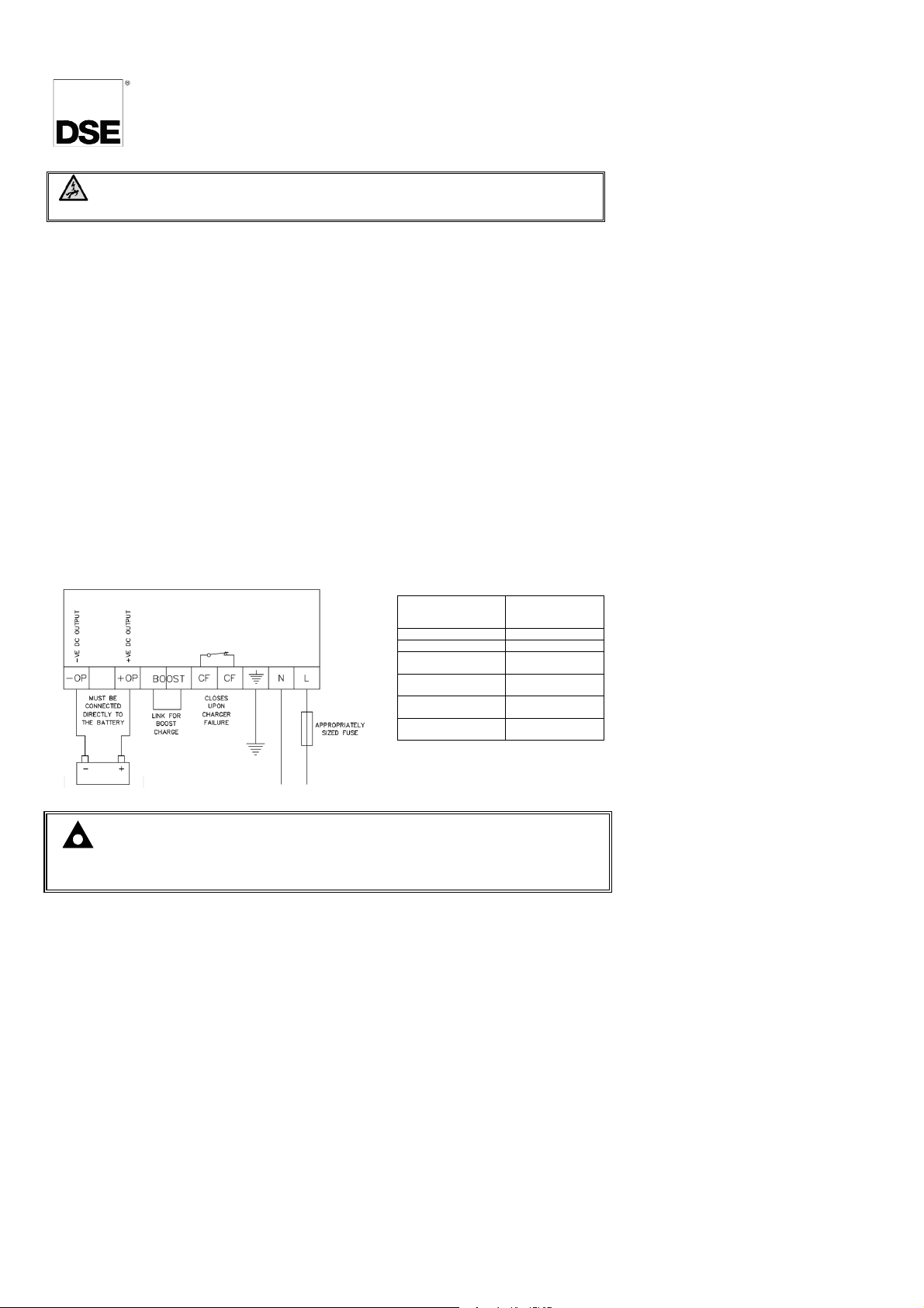
Typical Wiring Diagram
Connection Type Screw Terminal,
Min Cable Size 0.5mm² (AWG 20)
Max Cable Size 2.5mm² (AWG 14)
DSE9701 AC Fuse
(230 V AC Supply)
DSE9701 AC Fuse
(110 V AC Supply)
DSE9702 AC Fuse
(230 V AC Supply)
DSE9702 AC Fuse
(110 V AC Supply)
Rising Clamp,
No Internal Spring
2.0 A Anti-Surge
3.5 A Anti-Surge
1.0 A Anti-Surge
2.0 A Anti-Surge
NOTE : This document is intended as a ‘quick start’ guide only. For full
operating instructions and specifications, refer to DSE publication: 057-085
DSE9xxx Series Operator Manual.
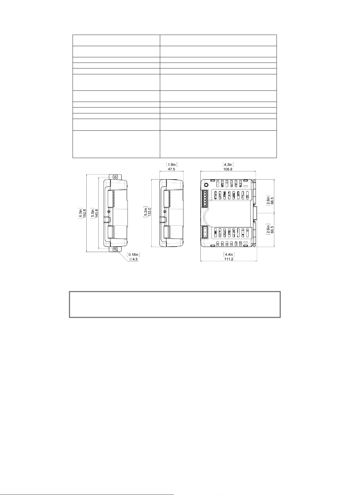
Dimensions and Mounting
Deep Sea Electronics Plc.
Deep Sea Electronics Inc.
Overall Size for DIN Rail Mounting 47.5 mm x 152.8 mm x 111.2 mm
(1.9” x 6.0” x 4.4”)
Overall Size for Chassis Mounting 47.5 mm x 133.0 mm x 111.2 mm
(1.9” x 5.2” x 4.4”)
Weight 0.4 kg
Mounting Type DIN Rail or Chassis Mounting
DIN Rail Type EN 50022 35 mm T ype Only
Mounting Holes
(DIN Rail Clips Pushed Outwards to
Suitable for M4
Reveal Mounting Holes)
Mounting Hole Centres 140.8 mm
(5.5”)
Input Voltage (Nominal) 110 V - 277 V
Input Voltage (Absolute Range) 90 V - 305 V
Charge Failure Relay Rating 3 A DC Resistive, 30 V Maximum
Operating Temperature
-30 °C to 55 °C
(-22 °F to 131 °F)
Over Temperature Protection Above 70 ºC (158 ºF) the maximum output current is
limited to protect the device. This limiting increases
linearly as temperature increases until at 100 ºC
(212 ºF), the maximum output current is limited to 1
A DC.
Chassis Mounting DIN rail Mounting Dimensions
Dimensions in mm unless otherwise specified
Tel:+44 (0)1723 890099
Fax: +44 (0)1723 893303
Email: sales@deepseaplc.com
Web: www.deepseaplc.com
Phone: +1 (815) 316-8706
Fax: +1 (815) 316- 8708
Email: sales@deepseausa.com
Web: www.deepseausa.com
 Loading...