

DSE DSE9474, DSE9484 Operator's Manual

ISSUE: 2
DEEP SEA ELECTRONICS PLC
DSE9474 & DSE9484 OPERATOR MANUAL
Document Number: 057-231
Author: A.D.Manton

DSE9474 & DSE9484 Operator Manual
057-231 ISSUE: 2 Page 2 of 30
Deep Sea Electronics PLC
Highfield House
Hunmanby
North Yorkshire
YO14 0PH
ENGLAND
Sales Tel: +44 (0) 1723 890099
Sales Fax: +44 (0) 1723 893303
E-mail: sales@deepseaplc.com
Website: www.deepseaplc.com
DSE9474 & DSE9484 Operator Manual
© Deep Sea Electronics PLC
All rights reserved. No part of this publication may be reproduced in any material form (including
photocopying or storing in any medium by electronic means or other) without the written permission of
the copyright holder except in accordance with the provisions of the Copyright, Designs and Patents
Act 1988.
Applications for the copyright holder’s written permission to reproduce any part of this publication
must be addressed to Deep Sea Electronics PLC at the address above.
Any reference to trademarked product names used within this publication is owned by their respective
companies.
Deep Sea Electronics Plc reserves the right to change the contents of this document without prior
notice.
Amendments since last publication
Issue
. No.
Comments
1 Initial release
2 Addition of DSE9484 information
Typeface : The typeface used in this document is Arial. Care should be taken not to mistake the upper
case letter I with the numeral 1. The numeral 1 has a top serif to avoid this confusion.

DSE9474 & DSE9484 Operator Manual
Page 3 of 30 057-231 ISSUE: 2
TABLE OF CONTENTS
Section
Page
1 INTRODUCTION .................................................................................................. 4
1.1 BIBLIOGRAPHY ................................................................................................................. 4
1.1.1 INSTALLATION INSTRUCTIONS ................................................................................. 4
1.1.2 MANUALS .................................................................................................................... 4
2 SPECIFICATIONS ............................................................................................... 5
2.1 ELECTRICAL SPECIFICATIONS ....................................................................................... 5
2.2 CHARGE FAIL RELAY ....................................................................................................... 6
2.3 OUTPUT SPECIFICATIONS ............................................................................................... 6
2.3.1 VOLTAGE DROP COMPENSATION ............................................................................ 6
2.3.2 BATTERY TEMPERATURE COMPENSATION ............................................................ 7
2.3.3 AMBIENT TEMPERATURE DEPENDENT CURRENT DERATING ............................... 8
2.3.4 INPUT POWER TO OUTPUT POWER EFFICIENCY ................................................... 9
2.4 DIMENSIONS AND MOUNTING ....................................................................................... 10
2.5 APPLICABLE STANDARDS............................................................................................. 11
2.6 COMMUNICATION PORT USAGE ................................................................................... 12
2.6.1 USB CONNECTION ................................................................................................... 13
2.6.2 RS485 ........................................................................................................................ 14
2.6.3 CAN ........................................................................................................................... 16
3 INSTALLATION ................................................................................................. 17
3.1 BATTERY SUITABILITY ................................................................................................... 17
3.2 USER CONNECTIONS ..................................................................................................... 18
3.2.1 AC SUPPLY CONNECTIONS .................................................................................... 18
3.2.2 INPUT, OUTPUT, AND RS485 CONNECTIONS ........................................................ 18
3.2.3 CANBUS AND TEMP SENSOR CONNECTIONS ....................................................... 19
3.2.4 BATTERY CONNECTIONS ........................................................................................ 19
3.3 TYPICAL WIRING DIAGRAM ........................................................................................... 20
4 INDICATIONS .................................................................................................... 21
4.1 STATUS............................................................................................................................ 22
4.2 FAULT CONDITIONS ....................................................................................................... 22
5 OPERATION ...................................................................................................... 23
5.1 PROTECTION ................................................................................................................... 23
5.1.1 FACTORY PRE-SET ALARMS ................................................................................... 23
5.1.2 USER CONFIGURABLE ALARMS ............................................................................. 23
5.2 DIGITAL INPUT ................................................................................................................ 24
5.3 PSU MODE ....................................................................................................................... 24
5.4 CHARGE MODE ............................................................................................................... 25
5.4.1 BULK CHARGE .......................................................................................................... 25
5.4.2 ABSORPTION ............................................................................................................ 25
5.4.3 FLOAT CHARGE........................................................................................................ 26
5.4.4 STORAGE.................................................................................................................. 26
5.4.5 CHARGING TIME....................................................................................................... 26
5.4.6 MANUAL BOOST ....................................................................................................... 26
5.4.7 TEMPERATURE COMPENSATION ........................................................................... 26
6 FAULT DIAGNOSIS........................................................................................... 27
7 MAINTENANCE, SPARES, REPAIR, AND SERVICING .................................. 28
8 WARRANTY ...................................................................................................... 28
9 DISPOSAL ......................................................................................................... 28
9.1 WEEE (WASTE ELECTRICAL AND ELECTRONIC EQUIPMENT) ................................... 28

Introduction
057-231 ISSUE: 2 Page 4 of 30
1 INTRODUCTION
This document details the installation requirements of the DSE9474 24 V 30 A battery charger &
DSE9484 12 V 30 A battery charger.
The manual forms part of the product and should be kept for the entire life of the product. If the
product is passed or supplied to another party, ensure that this document is passed to them for
reference purposes.
This is not a controlled document. You will not be automatically informed of updates. Any future
updates of this document will be added to the DSE website at www.deepseaplc.com.
The DSE9474 & DSE9484 battery chargers are intended for mounting within a customer enclosure or
panel, fastened by screws / bolts.
The DSE9474 & DSE9484 include protected outputs, intelligent charging and power supply operation
with a robust enclosure.
1.1 BIBLIOGRAPHY
This document refers to and is referred to by the following DSE publications, be obtained from the
DSE website www.deepseaplc.com
1.1.1 INSTALLATION INSTRUCTIONS
Installation instructions are supplied with the product in the box and are intended as a ‘quick start’
guide only.
DSE
Part Description
053-175 DSE9474 & DSE9484 Installation Instructions.
1.1.2 MANUALS
DSE
Part Description
057-159 DSE94xx Series Configuration Suite PC Software Manual.

Specifications
Page 5 of 30 057-231 ISSUE: 2
2 SPECIFICATIONS
2.1 ELECTRICAL SPECIFICATIONS
Parameter
Min Nominal
Max AC
Input Voltage (
V)
90 V 110 V to 277 V 305 V
Operating Temperature
-30 °C
80 °C
Input F
requency (Hz)
48 Hz 64 Hz
Output Ripple and Noise
1% Vo
Load Regulation
1% Vo
Line Regulation
<0.01% Vo
Output
V
oltage
O
vershoot %
<5%Vo
Transient Response Peak D
eviation (mV)
(at 50% to 100% load step)
<4% Vo
Warm Up V
oltage (V)
<1% Vo
Output Voltage Rise Time (ms)
<200 ms
Short Circuit P
rotection
Hiccup
Switching
F
requency (k
Hz)
42 kHz
Efficiency %
(See section entitled ‘output specifications’
elsewhere in this manual)
>90%
Temperature Sensor Input
PT1000

Specifications
057-231 ISSUE: 2 Page 6 of 30
2.2 CHARGE FAIL RELAY
Parameter
Specification
Relay Type Single Pole Change Over Relay. Energises when the battery charger is
operational and no alarms are present. De-energises upon any alarm and
when the AC power is removed from the charger.
Rating 3 A DC.
2.3 OUTPUT SPECIFICATIONS
Parameter
Min Nom
Max Comments
Output Voltage DSE9474
(24V DC Battery)
26 V 27 V 29.5 V
Voltage Drop Compensation is
provided when using Voltage Sensing
Wires.
Battery Temperature Compensation is
provided when using PT1000 sensor.
Output Voltage DSE9484
(12V DC Battery)
13 V 13.5 V 14.75 V
Output Charging Current (A) 0 A 30 A 31A
Current limit threshold (A) 15 A 30 A 31 A
Configurable by DSE Configuration
Suite PC Software.
Recovery from current limit
(A)
30 A 31 A
DSE9474 Full load AC input
current (A)
4.2 A At Vin = 230 V, Vo = 29.5 V, Io = 30 A
DSE9474 Full load AC input
current (A)
9 A At Vin = 110 V, Vo = 29.5 V, Io = 30 A
DSE9484 Full load AC input
current (A)
2.1 A At Vin = 230 V, Vo = 14.75 V, Io = 30 A
DSE9484 Full load AC input
current (A)
4.4 A At Vin = 110 V, Vo = 14.75 V, Io = 30 A
AC Input Inrush (10 ms)
current (A)
65 A For 10 ms
2.3.1 VOLTAGE DROP COMPENSATION
The battery voltage is monitored by means of the Sensing Wires. These wires carry only a small
sensing current and as such are not affected by the voltage drop experienced by the high current
carrying battery connection wires.
This provides for an accurate reading of the battery voltage and enables the battery charger to
increase output voltage to maintain the correct charging voltage “at the battery terminals” (Maximum
output 29.5 V).
Example:
Float Voltage configuration of the battery charger = 27.4 V
Charger output = 27.4 V
Battery voltage measured by Sensing Wires = 25 V
The battery charger increases the output voltage until the Sensing Wires measure 27.4 V. The
voltage drop in the charging cables is eliminated.
Specifications
Page 7 of 30 057-231 ISSUE: 2
2.3.2 BATTERY TEMPERATURE COMPENSATION
NOTE: For further details of PC Configuration, refer to DSE Publication: 057-159
DSE94xx Battery Charger Series Configuration Suite PC Software Manual.
When suitably configured, the external PT1000 temperature sensor is used to monitor battery
temperature. As battery temperature increases, the output voltage is lowered as configured to suit the
battery requirements.
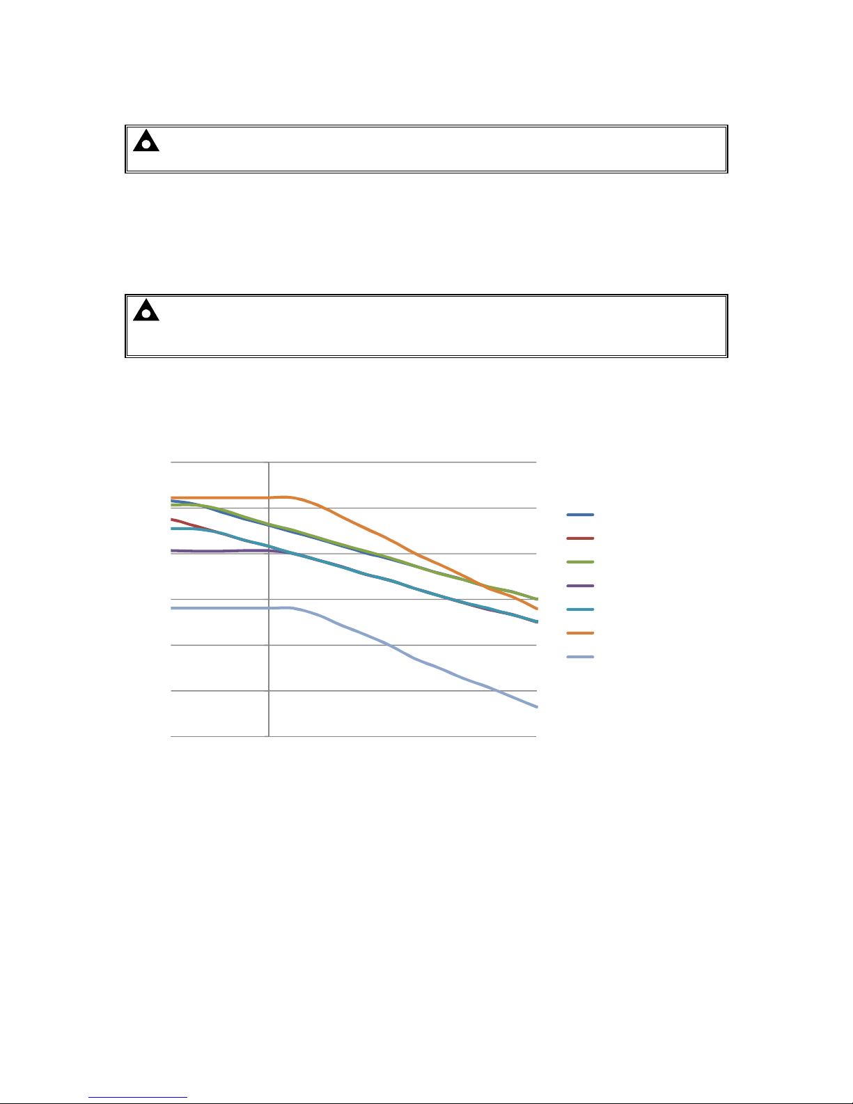
For example, the following Temperature to Voltage compensation curves are used for the pre-set
battery types. For custom battery types, the temperature compensation curve is user configurable.
NOTE: In the below chart, VRLA (Gel), Lead Acid Antimony and Wet Vented are
superimposed on each other for most of the curve.
Calcium and VRLA (AGM) are superimposed on each other for most of the curve.
Example:
A Lead Acid battery at 40 ºC is charged at 2.18 V per cell.
The same Lead Acid battery at 0 ºC is charged at 2.30 V per cell.
1.9
2
2.1
2.2
2.3
2.4
2.5
-20 -10 0 10 20 30 40 50
Volts/Cell
Temperature (ºC)
Battery Temperature Float Voltage Compensation
Calcium
Lead Acid Antimony
VRLA(AGM)
VRLA(GEL)
Wet Vented Lead Acid
NiCd 10/20
NiCd 9/18

Specifications
057-231 ISSUE: 2 Page 8 of 30
2.3.3 AMBIENT TEMPERATURE DEPENDENT CURRENT DERATING
The battery charger is rated at full current to 55 ºC. As the temperature increases above 55 ºC, the
maximum output current derates to keep the charger within operational parameters and to prevent
overheating of the device. An internal temperature sensor is used to determine ambient temperature.
2.3.3.1 TEMPERATURE DERATING (AC VOLTAGE BETWEEN 110 V AND 305 V)
Example:
For AC voltage of between 110 V and 305 V, if the ambient termperature is 73 ºC, the charger is
limited to 40% of it’s configured current rating.
2.3.3.2 TEMPERATURE DERATING (AC VOLTAGE BELOW 110 V AND AMBIENT TEMP BELOW 50 ºC)
Example:
For AC voltage 108 V, if the ambient termperature is below 50 ºC, the charger is limited to 25 A
maximum.
0
20
40
60
80
100
120
-40 -20 0 20 40 50 60 70 75 80
Perecentage of Nominal Current (%)
Ambient Temperature (ºC)
Output Current Derating Curve (110 V<Vin<305 V)
0
5
10
15
20
25
30
35
95 100 105 110 115 120
Output Current (A)
Input Voltage (V)
Derating Curve <110 V and <50 ºC Ambient

Specifications
Page 9 of 30 057-231 ISSUE: 2
2.3.4 INPUT POWER TO OUTPUT POWER EFFICIENCY
Efficiency of the battery charger is important in terms of minimising power losses in the battery
charger and also in terms of the heat generated by the battery charger.
The following charts show the high efficiency of the DSE947 & DSE9484
2.3.4.1 INPUT POWER TO OUTPUT POWER EFFICIENCY DSE9474
2.3.4.2 INPUT POWER TO OUTPUT POWER EFFICIENCY DSE9484
Example:
With an input voltage of 240 V AC, more than 93.5 % of the input power to the battery charger is
passed to the battery. resulting in less than 6.5 % of the power being used to supply the battery
charger.
88
89
90
91
92
93
94
110 230 277
Efficiency (%)
Input Voltage (V)
DSE9474 Efficiency Curve
88
89
90
91
92
93
94
110
230
277
Efficiency (%)
Input Voltage (V)
DSE9484 Efficiency Curve
 Loading...