

DSE DSE9462 Installation Instructions Manual
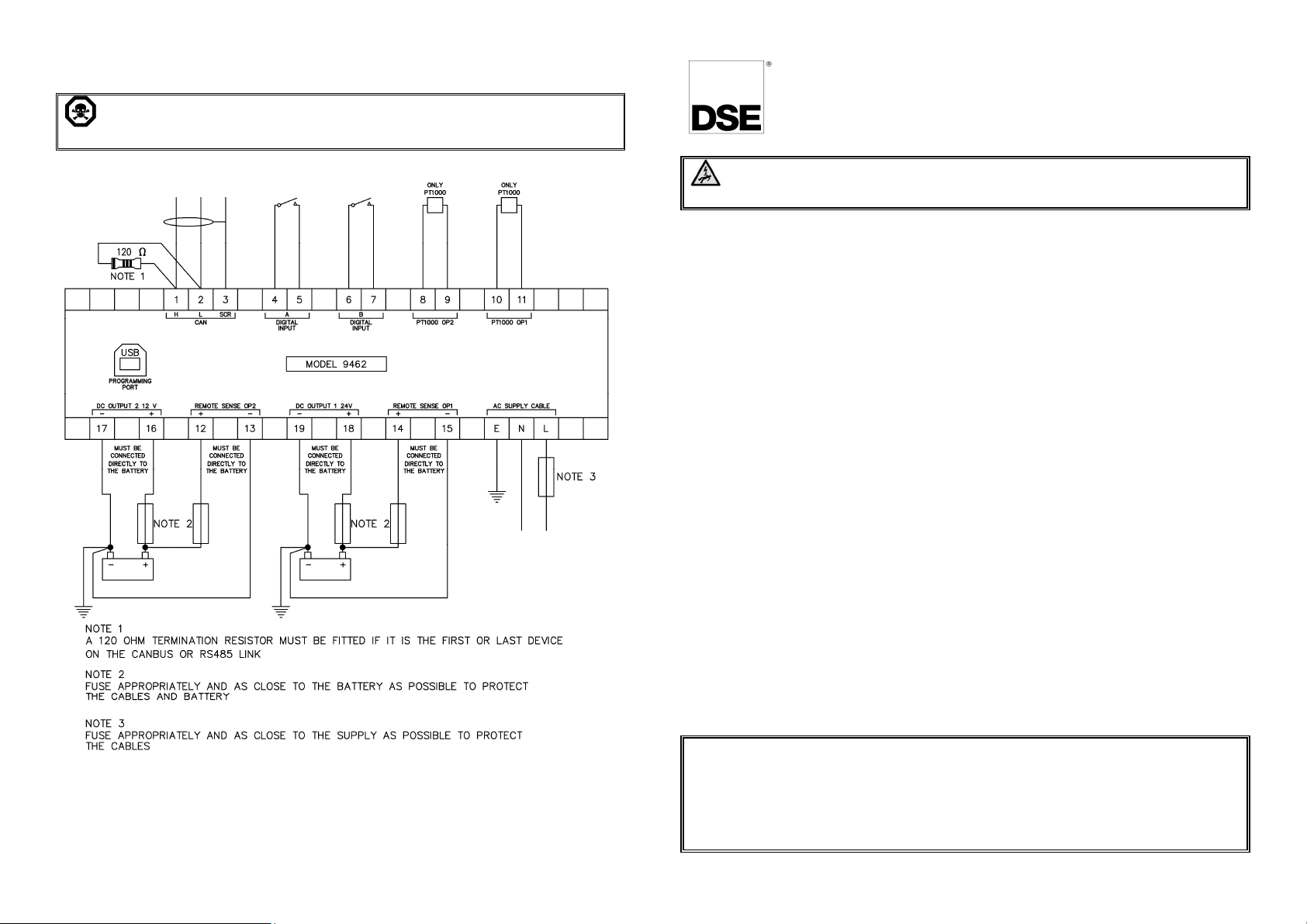
TYPICAL WIRING DIAGRAM
sure.
WARNING!: Ensure the Remote Sensing Wires are connect to the
correct battery to prevent damage caused by overcharging.
DEEP SEA ELECTRONICS
053-189
ISSUE 1
DSE9462 Installation Instructions
DANGER OF DEATH: LIVE PARTS exist within the DSE9462 enclo
The enclosure cover must not be removed.
INSTALLATION
The battery charger is designed to be mounted within a control panel, utilising the
integral mounting holes. The battery charger is fit-and-forget. It may be
permanently connected to the supply and the load, with no requirement to disable
the charger during times of heavy load (such as engine cranking) or when in
parallel with a charging alternator.
BATTERY SUITABILITY
The charger is factory set by DSE to suit Lead Acid batteries and may be ordered
to suit other battery types. Additionally, configuration is possible using the DSE
Configuration Suite PC Software to suit other battery types.
Care must be taken to ensure the batteries connected to the charger are of the
correct ‘technology’ to suit the setting of the charger.
INDICATIONS
The DSE9462 Battery Charger features LED indicators to show the battery charger
Status.
Deep Sea Electronics Plc.
Tel:+44 (0)1723 890099
Fax: +44 (0)1723 893303
Email: sales@deepseaplc.com
Web: www.deepseaplc.com
Deep Sea Electronics Inc.
Phone: +1 (815) 316-8706
Fax: +1 (815) 316- 8708
Email: sales@deepseausa.com
Web: www.deepseausa.com
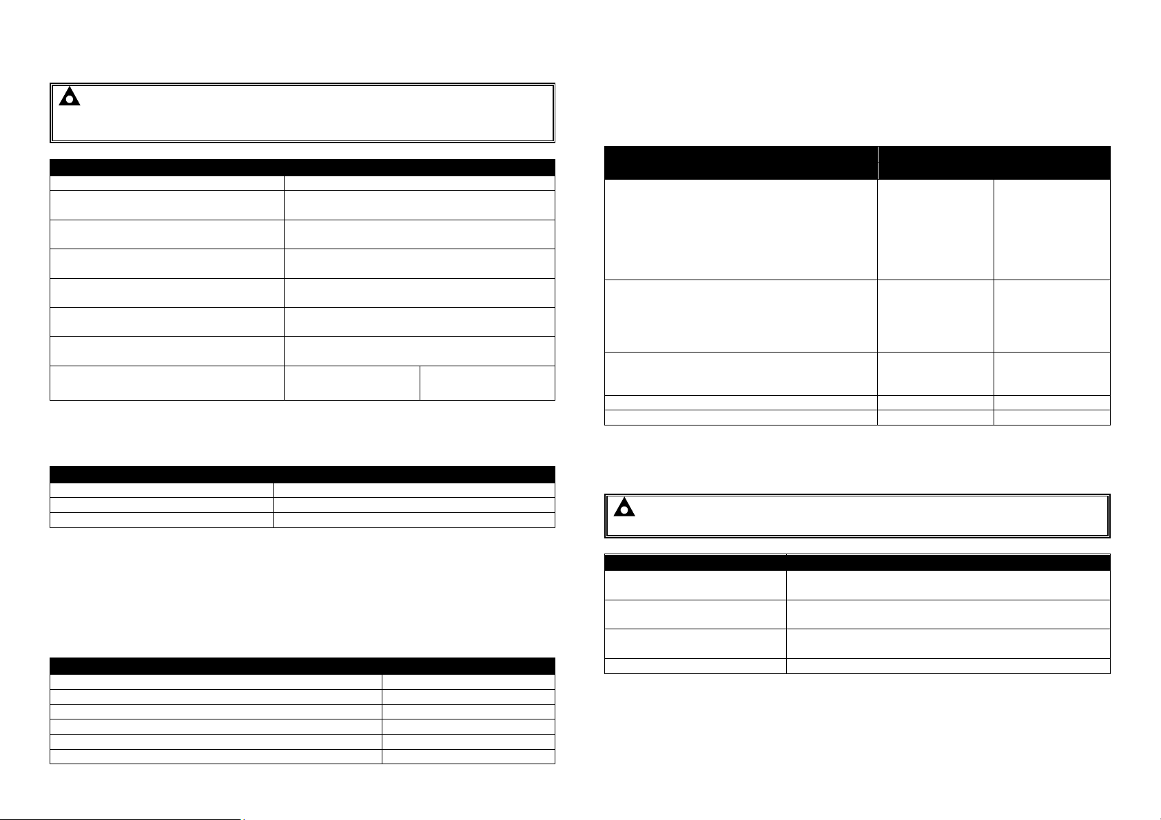
SPECIFICATIONS
Description
Specification
230 V AC Input
110 V AC Input
Connection
Cable Colour
Condition
Status LED
LED
Fault 1
Fault 2
Description
Dimension
NOTE: This document is intended as a ‘quick start’ guide only. For full
operating instructions and specifications, refer to DSE publication:
057-255 DSE9462 Operator Manual.
Connection Type Cage clamp terminals
Min Cable Size Accepted in Terminal
(Battery Connection)
Max Cable Size Accepted in Terminal
(Battery Connection)
Strip Length (Battery Connection)
Min Cable Size Accepted in Terminal
(Other Connections)
Max Cable Size Accepted in Terminal
(Other Connections)
Strip Length (Other Connections)
Recommended AC Fuse
0.08 mm² (AWG 28)
4.0 mm² (AWG 12)
8 mm to 9 mm
(0.31 “ to 0.35 “)
0.08 mm² (AWG 28)
2.0 mm² (AWG 14)
7 mm to 8 mm
(0.28 “ to 0.31 “)
10 A anti-surge 10 A anti-surge
MAINS SUPPLY CABLE
L1 Brown
Neutral Blue
Earth Green and Yellow
STATUS LEDS
Each output has its own dedicated LED to show charge status.
Status 1: Charge status of Output 1.
Status 2: Charge status of Output 2.
Output Not Charging (Due to Fault or Charger Off) Off
Battery Detection Mode Green Constant
Bulk (Boost) Charge in Progress Yellow Constant
Absorption Charge in Progress Yellow Flashing
Float Charge in Progress Green Constant
Storage Charge in Progress Green Flashing
FAULT LEDS
Two Fault LEDs, Fault 1 and Fault 2 are used to indicate faults. Output 1 and
Output 2 share these indications. Where two alarms are present at the same time,
the most critical is displayed.
Condition
DC Over Volts Warning and Trip
DC Under Volts Warning
Battery Detection Warning
DC Over Current
Battery Reverse Polarity
Short Circuit Protection
Battery Detection Warning
Input Fuse Failure
AC Under Voltage Warning and Trip
AC Over Volts Warning and Trip
DC Over Current Warning
Cable Voltage Drop Alarm
Battery Over Temperature Warning and Trip
Battery Temperature Sensor (PT1000) Fail
Ambient Over Temperature
Battery Charger Failure Red Constant Red Constant
Battery Detection Mode - Battery Not Detected Red Flashing Red Flashing
Red Constant Off
Red Flashing Off
Off Red Constant
DIMENSIONS AND MOUNTING
NOTE: The DSE battery charger is designed to be mounted with the
base to a vertical surface with the connection terminals at the bottom.
Case Dimensions
Mounting Holes Dimensions
Mounting Hole Spacing
Required Ventilation Spacing 100 mm (3.9 ”) air space around the battery charger.
162 mm x 291 mm x 74 mm
(6.4 ” x 11.5 ” x 2.9”)
Suitable for M5
(0.2 ” diameter)
95 mm x 279 mm
(3.7 ” x 11.0 ”)
 Loading...