

DSE DSE9460, DSE9461 Operator's Manual

DSE ENCLOSED INTELLIGENT BATTERY CHARGER OPERATOR MANUAL ISSUE 2
DEEP SEA ELECTRONICS PLC
DSE ENCLOSED INTELLIGENT BATTERY
CHARGER OPERATOR MANUAL
Document Number: 057-176
Author: Anthony Manton

DSE Enclosed Intelligent Battery Charger Operator Manual
2
Deep Sea Electronics Plc
Highfield House
Hunmanby
North Yorkshire
YO14 0PH
ENGLAND
Sales Tel: +44 (0) 1723 890099
Sales Fax: +44 (0) 1723 893303
E-mail: sales@deepseaplc.com
Website: www.deepseaplc.com
DSE Enclosed Intelligent Battery Charger Operator Manual
© Deep Sea Electronics Plc
All rights reserved. No part of this publication may be reproduced in any material form (including
photocopying or storing in any medium by electronic means or other) without the written permission of
the copyright holder except in accordance with the provisions of the Copyright, Designs and Patents
Act 1988.
Applications for the copyright holder’s written permission to reproduce any part of this publication
should be addressed to Deep Sea Electronics Plc at the address above.
Any reference to trademarked product names used within this publication is owned by their respective
companies.
Deep Sea Electronics Plc reserves the right to change the contents of this document without prior
notice.
Amendments since last publication
Issue
. No.
Comments
1 First Release
2 Added new FPE table
Typeface : The typeface used in this document is Arial. Care should be taken not to mistake the upper
case letter I with the numeral 1. The numeral 1 has a top serif to avoid this confusion.

DSE Enclosed Intelligent Battery Charger Operator Manual
3
TABLE OF CONTENTS
1 BIBLIOGRAPHY .................................................................................................. 5
1.1 INSTALLATION INSTRUCTIONS ....................................................................................... 5
1.2 MANUALS .......................................................................................................................... 5
3 SPECIFICATIONS ............................................................................................... 6
3.2 PROTECTION ..................................................................................................................... 7
3.3 ELECTRICAL SPECIFICATIONS ....................................................................................... 8
3.4 OUTPUT SPECIFICATIONS ............................................................................................... 9
3.4.1 DSE9460 24V/12V 5A .................................................................................................. 9
3.4.2 DSE9461 24V/12V 10A .............................................................................................. 11
3.5 COMMUNICATION PORTS .............................................................................................. 13
3.5.1 USB CONNECTION ................................................................................................... 13
3.5.2 RS485 ........................................................................................................................ 14
3.7 DIMENSIONS AND MOUNTING ....................................................................................... 16
3.8 APPL ICABLE ST ANDARDS............................................................................................. 17
4 INSTALLAT ION ................................................................................................. 18
4.1 BATTERY SUITABILITY ................................................................................................... 18
4.2 USER CONNECTIONS ..................................................................................................... 19
4.2.1 BATTERY CHARGER ................................................................................................ 19
4.2.2 TYPICAL CONNECTION DIAGRAM ........................................................................... 21
4.3 DSE2541 ENCLOSURE MOUNTED DISPLAY MODULE ................................................. 22
5 INDICATIONS .................................................................................................... 23
5.1 LCD DISPLAY .................................................................................................................. 23
5.1.1 CHARGER STATUS................................................................................................... 23
5.1.2 FAULT STATUS ......................................................................................................... 23
5.1.3 BOOST MODE ........................................................................................................... 23
5.2 ENCLOSURE MOUNTED LEDS ....................................................................................... 24
5.2.1 STATUS ..................................................................................................................... 24
5.2.2 CHARGE MODE ........................................................................................................ 24
5.2.3 FAULT CONDITIONS ................................................................................................. 25
5.3 ENCLOSURE MOUNTED ANALOGUE METERS ............................................................. 25
6 OPERATION ...................................................................................................... 26
6.1 OPERATING MODES ....................................................................................................... 26
6.1.1 PSU MODE ................................................................................................................ 26
6.1.2 CHARGE MODE ........................................................................................................ 26
6.1.3 BOOST MODE ........................................................................................................... 27
6.1.4 TEMPERATURE COMPENSATION ........................................................................... 27
6.2 OPERATION OF LCD DISPLAY ....................................................................................... 30
6.2.1 BACKLIGHT ............................................................................................................... 30
6.2.2 LED ............................................................................................................................ 30
6.2.3 CONTROL BUTTONS ................................................................................................ 30
6.2.4 SUMMARY SCREEN ................................................................................................. 31
6.2.5 LINK ICON ................................................................................................................. 31
6.2.6 BATTERY ICON ......................................................................................................... 31
6.2.7 CHARGE GRAPHIC ................................................................................................... 32
6.2.8 VIEWING THE INSTRUMENTATION ......................................................................... 34
6.3 FRONT PANEL EDITOR ................................................................................................... 37
6.3.1 ACCESSING THE FRONT PANEL EDITOR ............................................................... 37
6.3.2 SELECTING A PARAMETER ..................................................................................... 37
6.3.3 FRONT PANEL EDITOR PARAMETERS ................................................................... 38
7 MODBUS ........................................................................................................... 41
7.1 READING VALUES .......................................................................................................... 41
7.2 WRITING VALUES ...... ..................................................................................................... 42
7.2.1 TOGGLE BOOST MODE............................................................................................ 42
7.2.2 TOGGLE CHARGER ON/OFF .................................................................................... 42

DSE Enclosed Intelligent Battery Charger Operator Manual
4
8 FAULT DIAGNOSIS ........................................................................................... 43
9 MAINTENANCE, SPARES, REPAIR AND SERVICING ................................... 44
10 WARRANTY ................................................................................................... 44
11 DISPOSAL ...................................................................................................... 44
11.1 WEEE (WASTE ELECTRICAL AND ELECTRONIC EQUIPMENT) ............................... 44

Bibliography
5
1 BIBLIOGRAPHY
This document refers to and is referred to by the following DSE publications which can be obtained
from the DSE website www.deepseaplc.com
1.1 INSTALLATION INSTRUCTIONS
Installation instructions are supplied with the product in the box and are intended as a ‘quick start’
guide only.
DSE PART
DESCRIPTION
053-148 DSE9460 / DSE9461 Enclosed Intelligent Battery Charger Installation Instructions
053-154 DSE2541 Remote Battery Charger Display Installation Instructions
1.2 MANUALS
DSE PART
DESCRIPTION
057-159 DSE9400 Series Configuration Suite PC Software Manual
2 INTRODUCTION
This document details the installation requirements of the DSE range of enclosed intelligent battery
chargers.
The manual forms part of the product and should be kept for the entire life of the product. If the
product is passed or supplied to another party, ensure that this document is passed to them for
reference purposes.
This is not a controlled document. You will not be automatically informed of updates. Any future
updates of this document will be added to the DSE website at www.deepseaplc.com.
The enclosed intelligent battery chargers fulfill the most common functions required of a charger in the
generating set industry. Combining a range of display options, protected outputs, intelligent charging
and power supply operation with a robust enclosure.
Specifications
6
3 SPECIFICATIONS
3.1 PART NUMBERING
9460 - 001 - 00
NOTE: DSE9460 Chargers are factory preconfigured for max 5A charging. However the
maximum current can be adjusted between 1A and 5A using DSE Configuration Suite PC
Software.
NOTE: DSE9461 Chargers are factory preconfigured for max 10A charging. However the
maximum current can be adjusted between 2A and 10A using DSE Configuration Suite PC
Software.
NOTE: Chargers are factory preconfigured to suit 12V or 24V batteries (see part numbers
above). However a charger can be freely changed from 12V to 24V using DSE Configuration
Suite PC Software.
NOTE: Chargers are supplied configured to be suitable for Lead Acid batteries.
Configuration to suit other battery types is performed using DSE Configuration Suite PC
Software.
Product type
Variant
Hardware revisions
First version hardware
001
01
12V With LCD Display and
analogue meters
02
12V With LED Indicators
and Analogue Meters
03
12V With LED Indicators
04
DSE9460 12V/24V 5A
9460
DSE9461 12V/24V 10A
9461
12V With LCD Display
11
24V With LCD Display and
analogue meters
12
24V With LED Indicators
and Analogue Meters
13
24V With LED Indicators
14
24V With LCD Display

Specifications
7
3.2 PROTECTION
• High Output Voltage (DC) detection.
• High / Low Input Voltage (AC) detection.
• Current limit to charger specification (5A or 10A depending upon charger model) with High Output
Current detection.
• High Ambient Temperature detection.
• High Battery Temperature detection (when enabled).
• Short circuit protection. Charger automatically restarts operation after the fault is remov ed.
• Reverse battery polarity protection. Charger automatically restarts operation after the fault is
removed.
• Battery Charger Failure. Informs of an internal fault with the battery charger.
• Common Fault Relay output.

Specifications
8
3.3 ELECTRICAL SPECIFICATIONS
Parameter
Min Nominal
Max AC
Input Voltage (V)
95V 110V-277V 305V
Operating Temperature
-30°C
85°C with de-ratings
Input F
requency (Hz)
48Hz 64Hz
Output Ripple and Noise
1% Vo
Load Regulation
1% Vo
Line
R
egulation
<0.01% Vo
Output
V
oltage
O
vershoot %
<5%Vo
Transient Response Peak D
eviation (mV)
(at 50% to 100% load step)
<4% Vo
Warm Up V
oltage (V)
<1% Vo
Output Voltage Rise Time (ms)
<200ms
Short Circuit P
rotection
Hiccup
Switching
F
requency (k
Hz)
67kHz
Efficiency %
>85%
Temperature Sensor Input
PT1000
NOTE: Check the de-rating and efficieny curves in the following sections of this manual.

Specifications
9
3.4 OUTPUT SPECIFICATIONS
3.4.1 DSE9460 24V/12V 5A
Parameter
Min Nominal
Max Comments
Output Voltage 9V Configurable 29.5V
Output Charging Current (A) 2A 5A 6A
Current limit threshold (A) 5A 6A
Recovery from current limit (A) 5A 6A
Full load AC input current (A) 1.5A
At Vin=230 V, Vo=28.2 V,
Io=5 Amp
Full load AC input current (A) 2.5A
At Vin=110 V, Vo=28.2 V,
Io=10 Amp
AC Input Inrush (10ms) current (A) 60A For 10ms
0.780
0.800
0.820
0.840
0.860
0.880
0.900
0.920
0.940
110
230
268
Efficiency (%)
Input Voltage (V)
Efficiency Curve at 5A

Specifications
10
0
20
40
60
80
100
120
051015202530354045505560657075808590
Nominal Current (%)
Temperature (ºC)
De-rating Curve
110V < Vin < 305V Charger De-rat ing Curve
0
10
20
30
40
50
051015202530354045505560657075808590
Nominal Current (%)
Temperature (ºC)
De-rating Curve
90V < Vin < 110V Charger De-rating Curve

Specifications
11
3.4.2 DSE9461 24V/12V 10A
Parameter
Min Nominal
Max Comments
Output Voltage 9V Configurable 30.5V
Output Charging Current (A) 2A 10A 11A
Current limit threshold (A) 10A 11A
Recovery from current limit (A) 10A 11A
Full load AC input current (A) 1.2A
At Vin=230V, Vo=14.4V,
Io=10Amp
Full load AC input current (A) 2.2A
At Vin=110V, Vo=14.4V,
Io=10Amp
AC Input Inrush (10ms) current
(A)
60A For 10ms
87%
87%
88%
88%
89%
89%
90%
90%
91%
91%
92%
110 230 277
Efficiency (%)
Input Voltage (V)
Efficiency Curve at 10A

Specifications
12
0
20
40
60
80
100
120
051015202530354045505560657075808590
Nominal Current (%)
Temperature (ºC)
De-rating Curve
110V < Vin < 305V Charger De-rat ing Curve
0
10
20
30
40
50
051015202530354045505560657075808590
Nominal Current (%)
Temperature (ºC)
De-rating Curve
90V < Vin < 110V Charger De-rating Curve

Specifications
13
3.5 COMMUNICATION PORTS
Communication
Specification
USB Port
USB2.0 Device for connection to PC running DSE Configuration Suite
Max distance 6m (20 feet)
RS485 Serial
Port
Isolated
Data connection 2 wire + common
Half Duplex
Data direction control for Transmit (by s/w protocol)
Max Baud Rate 19200
External termination required (120Ω)
Max common mode offset 70V (on board protection transorb)
Max distance 1.2km (¾ mile)
Display
Communication
Port
Reserved for connection to fascia mounted LCD display module.
3.5.1 USB CONNECTION
The USB port is provided to give a simple means of connection between a PC and the DSE9400
series battery charger. Using the DSE Configuration Suite Software, the operator is then configure
and monitor the state of the battery charger.
To connect a DSE9400 series battery charger to a PC by USB, the following items are required:
• DSE Enclosed Intelligent Battery Charger.
• DSE Configuration Suite Software
(Supplied on configuration suite software CD or available from
www.deepseaplc.com).
•
USB cable Type A to Type B.
(This is the same cable as often used between a PC and a USB
printer)
DSE can supply this cable if required :
PC Configuration interface lead (USB type A – type B)
DSE Part No 016-125
NOTE: - Refer to Enclosed Intelligent Battery Charger PC Software Configuration Manual
for further details on configuring and monitoring.

Specifications
14
3.5.2 RS485
The RS485 port on the battery charger supports the Modbus RTU protocol.
RS485 is used for point-to-point cable connection of more than one device (maximum 32 devices)
and allows for connection to PCs, PLCs and Building Management Systems (to name just a few
devices).
One advantage of the RS485 interface is the large distance specification (1.2km) when using Belden
9841 (or equivalent) cable. This allows for a large distance between the battery charger and a PC
running the DSE Configuration Suite software. The operator is then able to view the various operating
parameters.
NOTE: - For distances up to 6m (8yds) the USB connection method is more suitable and
provides for a lower cost alternative to RS485 (which is more suited to longer distance
connections).
Cable Type Two core screened twisted pair
Cable Characteristic
Impedance
120Ω
Recommended Cable Belden 9841
Belden 9271
Maximum Cable Length 1200m (¾ mile) when using Belden 9841 or direct equivalent.
600m (666 yds) when using Belden 9271 or direct equivalent.
RS485 Topology “Daisy Chain” Bus with no stubs (spurs)
RS485 Termination
120Ω. Termination resistor must be fitted externally to the ‘first’ and
‘last’ expansion module by the customer as required by the RS485
specification.
Specifications
15
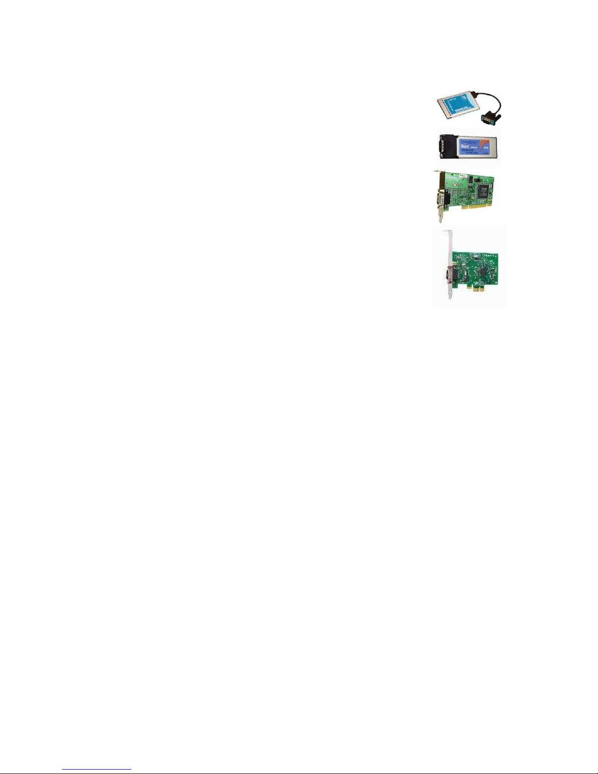
3.5.2.1 RECOMMENDED RS485 EXPANSION FOR DESKTOP AND LAPTOP PC’S
• Brainboxes PM154 PCMCIA RS485 card (for laptops PCs)
Set to ‘Half Duplex, Autogating” with ‘CTS True’ set to ‘enabled’
• Brainboxes VX-023 ExpressCard 1 Port RS422/485 (for laptops and
nettop PCs)
• Brainboxes UC320 PCI Velocity RS485 card (for desktop PCs)
Set to ‘Half Duplex, Autogating” with ‘CTS True’ set to ‘enabled’
• Brainboxes PX-324 PCI Express 1 Port RS422/485 (for desktop PCs)
Supplier:
Brainboxes
Tel: +44 (0)151 220 2500
Web: http://www.brainboxes.com
Email: Sales: sales@brainboxes.com
 Loading...