

Page 1

DSE ENCLOSED INTELLIGENT BATTERY CHARGER OPERATOR MANUAL ISSUE 2
DEEP SEA ELECTRONICS PLC
DSE ENCLOSED INTELLIGENT BATTERY
CHARGER OPERATOR MANUAL
Document Number: 057-176
Author: Anthony Manton
Page 2

DSE Enclosed Intelligent Battery Charger Operator Manual
2
Deep Sea Electronics Plc
Highfield House
Hunmanby
North Yorkshire
YO14 0PH
ENGLAND
Sales Tel: +44 (0) 1723 890099
Sales Fax: +44 (0) 1723 893303
E-mail: [email protected]
Website: www.deepseaplc.com
DSE Enclosed Intelligent Battery Charger Operator Manual
© Deep Sea Electronics Plc
All rights reserved. No part of this publication may be reproduced in any material form (including
photocopying or storing in any medium by electronic means or other) without the written permission of
the copyright holder except in accordance with the provisions of the Copyright, Designs and Patents
Act 1988.
Applications for the copyright holder’s written permission to reproduce any part of this publication
should be addressed to Deep Sea Electronics Plc at the address above.
Any reference to trademarked product names used within this publication is owned by their respective
companies.
Deep Sea Electronics Plc reserves the right to change the contents of this document without prior
notice.
Amendments since last publication
Issue
. No.
Comments
1 First Release
2 Added new FPE table
Typeface : The typeface used in this document is Arial. Care should be taken not to mistake the upper
case letter I with the numeral 1. The numeral 1 has a top serif to avoid this confusion.
Page 3

DSE Enclosed Intelligent Battery Charger Operator Manual
3
TABLE OF CONTENTS
1 BIBLIOGRAPHY .................................................................................................. 5
1.1 INSTALLATION INSTRUCTIONS ....................................................................................... 5
1.2 MANUALS .......................................................................................................................... 5
3 SPECIFICATIONS ............................................................................................... 6
3.2 PROTECTION ..................................................................................................................... 7
3.3 ELECTRICAL SPECIFICATIONS ....................................................................................... 8
3.4 OUTPUT SPECIFICATIONS ............................................................................................... 9
3.4.1 DSE9460 24V/12V 5A .................................................................................................. 9
3.4.2 DSE9461 24V/12V 10A .............................................................................................. 11
3.5 COMMUNICATION PORTS .............................................................................................. 13
3.5.1 USB CONNECTION ................................................................................................... 13
3.5.2 RS485 ........................................................................................................................ 14
3.7 DIMENSIONS AND MOUNTING ....................................................................................... 16
3.8 APPL ICABLE ST ANDARDS............................................................................................. 17
4 INSTALLAT ION ................................................................................................. 18
4.1 BATTERY SUITABILITY ................................................................................................... 18
4.2 USER CONNECTIONS ..................................................................................................... 19
4.2.1 BATTERY CHARGER ................................................................................................ 19
4.2.2 TYPICAL CONNECTION DIAGRAM ........................................................................... 21
4.3 DSE2541 ENCLOSURE MOUNTED DISPLAY MODULE ................................................. 22
5 INDICATIONS .................................................................................................... 23
5.1 LCD DISPLAY .................................................................................................................. 23
5.1.1 CHARGER STATUS................................................................................................... 23
5.1.2 FAULT STATUS ......................................................................................................... 23
5.1.3 BOOST MODE ........................................................................................................... 23
5.2 ENCLOSURE MOUNTED LEDS ....................................................................................... 24
5.2.1 STATUS ..................................................................................................................... 24
5.2.2 CHARGE MODE ........................................................................................................ 24
5.2.3 FAULT CONDITIONS ................................................................................................. 25
5.3 ENCLOSURE MOUNTED ANALOGUE METERS ............................................................. 25
6 OPERATION ...................................................................................................... 26
6.1 OPERATING MODES ....................................................................................................... 26
6.1.1 PSU MODE ................................................................................................................ 26
6.1.2 CHARGE MODE ........................................................................................................ 26
6.1.3 BOOST MODE ........................................................................................................... 27
6.1.4 TEMPERATURE COMPENSATION ........................................................................... 27
6.2 OPERATION OF LCD DISPLAY ....................................................................................... 30
6.2.1 BACKLIGHT ............................................................................................................... 30
6.2.2 LED ............................................................................................................................ 30
6.2.3 CONTROL BUTTONS ................................................................................................ 30
6.2.4 SUMMARY SCREEN ................................................................................................. 31
6.2.5 LINK ICON ................................................................................................................. 31
6.2.6 BATTERY ICON ......................................................................................................... 31
6.2.7 CHARGE GRAPHIC ................................................................................................... 32
6.2.8 VIEWING THE INSTRUMENTATION ......................................................................... 34
6.3 FRONT PANEL EDITOR ................................................................................................... 37
6.3.1 ACCESSING THE FRONT PANEL EDITOR ............................................................... 37
6.3.2 SELECTING A PARAMETER ..................................................................................... 37
6.3.3 FRONT PANEL EDITOR PARAMETERS ................................................................... 38
7 MODBUS ........................................................................................................... 41
7.1 READING VALUES .......................................................................................................... 41
7.2 WRITING VALUES ...... ..................................................................................................... 42
7.2.1 TOGGLE BOOST MODE............................................................................................ 42
7.2.2 TOGGLE CHARGER ON/OFF .................................................................................... 42
Page 4

DSE Enclosed Intelligent Battery Charger Operator Manual
4
8 FAULT DIAGNOSIS ........................................................................................... 43
9 MAINTENANCE, SPARES, REPAIR AND SERVICING ................................... 44
10 WARRANTY ................................................................................................... 44
11 DISPOSAL ...................................................................................................... 44
11.1 WEEE (WASTE ELECTRICAL AND ELECTRONIC EQUIPMENT) ............................... 44
Page 5

Bibliography
5
1 BIBLIOGRAPHY
This document refers to and is referred to by the following DSE publications which can be obtained
from the DSE website www.deepseaplc.com
1.1 INSTALLATION INSTRUCTIONS
Installation instructions are supplied with the product in the box and are intended as a ‘quick start’
guide only.
DSE PART
DESCRIPTION
053-148 DSE9460 / DSE9461 Enclosed Intelligent Battery Charger Installation Instructions
053-154 DSE2541 Remote Battery Charger Display Installation Instructions
1.2 MANUALS
DSE PART
DESCRIPTION
057-159 DSE9400 Series Configuration Suite PC Software Manual
2 INTRODUCTION
This document details the installation requirements of the DSE range of enclosed intelligent battery
chargers.
The manual forms part of the product and should be kept for the entire life of the product. If the
product is passed or supplied to another party, ensure that this document is passed to them for
reference purposes.
This is not a controlled document. You will not be automatically informed of updates. Any future
updates of this document will be added to the DSE website at www.deepseaplc.com.
The enclosed intelligent battery chargers fulfill the most common functions required of a charger in the
generating set industry. Combining a range of display options, protected outputs, intelligent charging
and power supply operation with a robust enclosure.
Page 6
Specifications
6
3 SPECIFICATIONS
3.1 PART NUMBERING
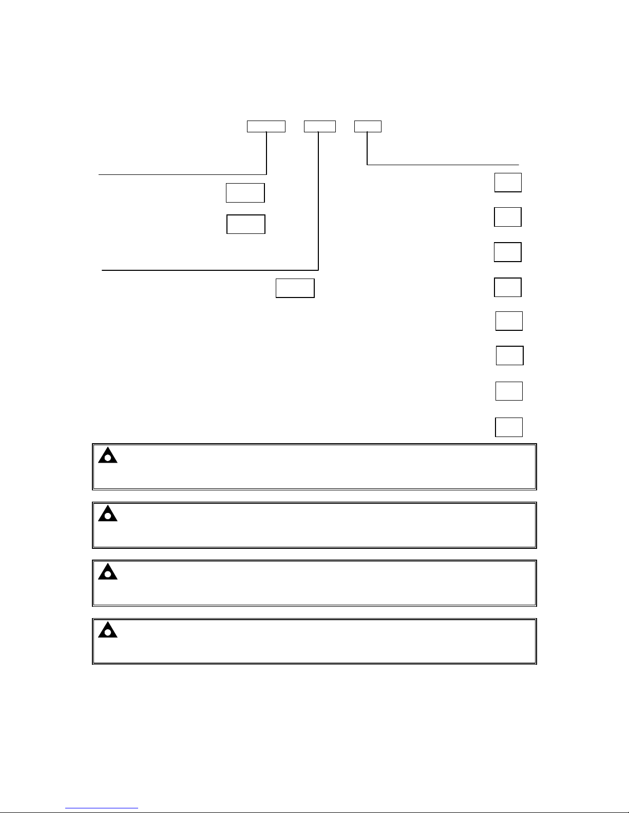
9460 - 001 - 00
NOTE: DSE9460 Chargers are factory preconfigured for max 5A charging. However the
maximum current can be adjusted between 1A and 5A using DSE Configuration Suite PC
Software.
NOTE: DSE9461 Chargers are factory preconfigured for max 10A charging. However the
maximum current can be adjusted between 2A and 10A using DSE Configuration Suite PC
Software.
NOTE: Chargers are factory preconfigured to suit 12V or 24V batteries (see part numbers
above). However a charger can be freely changed from 12V to 24V using DSE Configuration
Suite PC Software.
NOTE: Chargers are supplied configured to be suitable for Lead Acid batteries.
Configuration to suit other battery types is performed using DSE Configuration Suite PC
Software.
Product type
Variant
Hardware revisions
First version hardware
001
01
12V With LCD Display and
analogue meters
02
12V With LED Indicators
and Analogue Meters
03
12V With LED Indicators
04
DSE9460 12V/24V 5A
9460
DSE9461 12V/24V 10A
9461
12V With LCD Display
11
24V With LCD Display and
analogue meters
12
24V With LED Indicators
and Analogue Meters
13
24V With LED Indicators
14
24V With LCD Display
Page 7

Specifications
7
3.2 PROTECTION
• High Output Voltage (DC) detection.
• High / Low Input Voltage (AC) detection.
• Current limit to charger specification (5A or 10A depending upon charger model) with High Output
Current detection.
• High Ambient Temperature detection.
• High Battery Temperature detection (when enabled).
• Short circuit protection. Charger automatically restarts operation after the fault is remov ed.
• Reverse battery polarity protection. Charger automatically restarts operation after the fault is
removed.
• Battery Charger Failure. Informs of an internal fault with the battery charger.
• Common Fault Relay output.
Page 8

Specifications
8
3.3 ELECTRICAL SPECIFICATIONS
Parameter
Min Nominal
Max AC
Input Voltage (V)
95V 110V-277V 305V
Operating Temperature
-30°C
85°C with de-ratings
Input F
requency (Hz)
48Hz 64Hz
Output Ripple and Noise
1% Vo
Load Regulation
1% Vo
Line
R
egulation
<0.01% Vo
Output
V
oltage
O
vershoot %
<5%Vo
Transient Response Peak D
eviation (mV)
(at 50% to 100% load step)
<4% Vo
Warm Up V
oltage (V)
<1% Vo
Output Voltage Rise Time (ms)
<200ms
Short Circuit P
rotection
Hiccup
Switching
F
requency (k
Hz)
67kHz
Efficiency %
>85%
Temperature Sensor Input
PT1000
NOTE: Check the de-rating and efficieny curves in the following sections of this manual.
Page 9
Specifications
9
3.4 OUTPUT SPECIFICATIONS
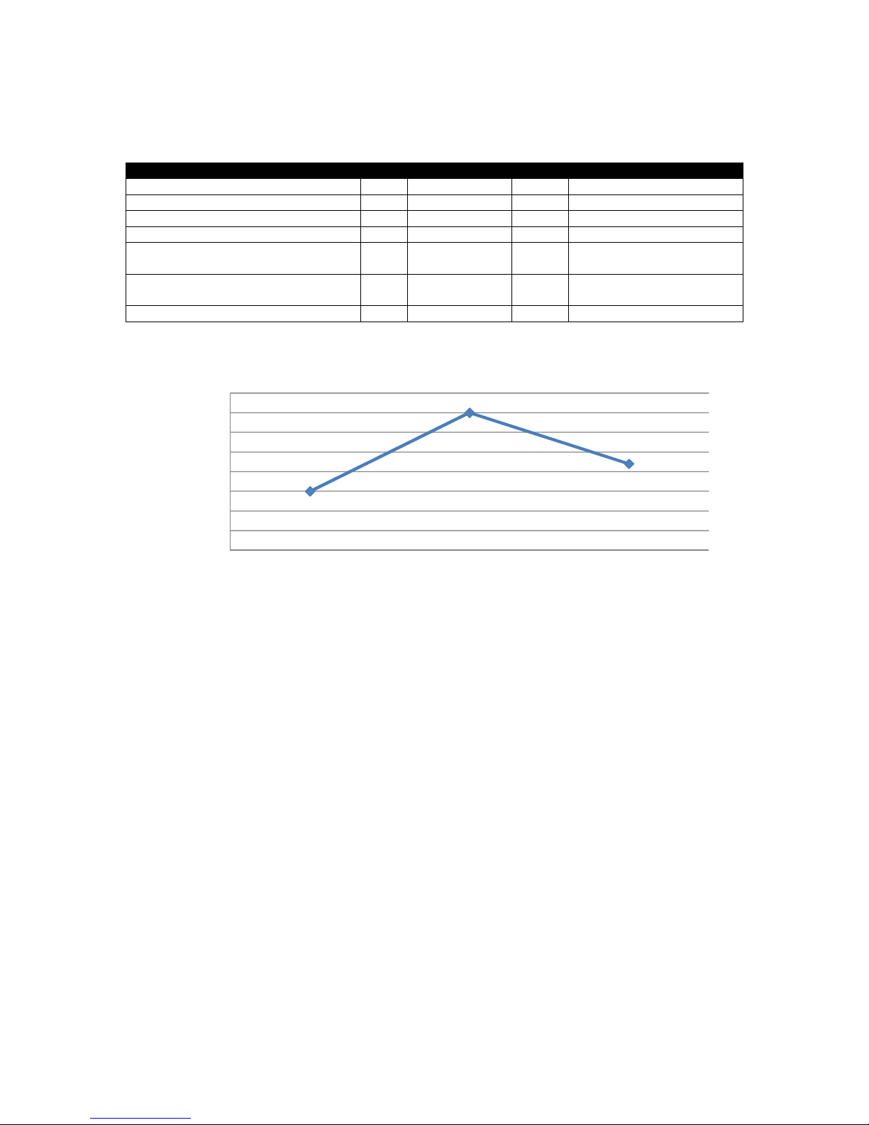
3.4.1 DSE9460 24V/12V 5A
Parameter
Min Nominal
Max Comments
Output Voltage 9V Configurable 29.5V
Output Charging Current (A) 2A 5A 6A
Current limit threshold (A) 5A 6A
Recovery from current limit (A) 5A 6A
Full load AC input current (A) 1.5A
At Vin=230 V, Vo=28.2 V,
Io=5 Amp
Full load AC input current (A) 2.5A
At Vin=110 V, Vo=28.2 V,
Io=10 Amp
AC Input Inrush (10ms) current (A) 60A For 10ms
0.780
0.800
0.820
0.840
0.860
0.880
0.900
0.920
0.940
110
230
268
Efficiency (%)
Input Voltage (V)
Efficiency Curve at 5A
Page 10
Specifications
10
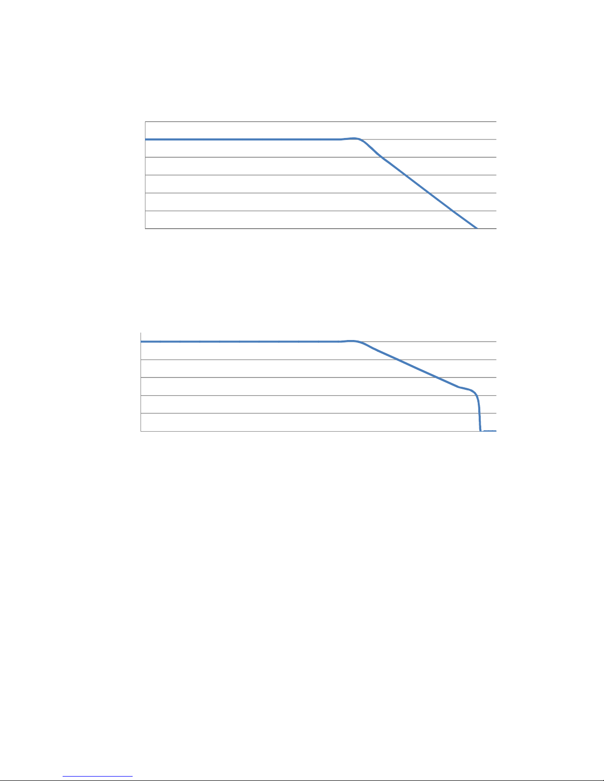
0
20
40
60
80
100
120
051015202530354045505560657075808590
Nominal Current (%)
Temperature (ºC)
De-rating Curve
110V < Vin < 305V Charger De-rat ing Curve
0
10
20
30
40
50
051015202530354045505560657075808590
Nominal Current (%)
Temperature (ºC)
De-rating Curve
90V < Vin < 110V Charger De-rating Curve
Page 11

Specifications
11
3.4.2 DSE9461 24V/12V 10A
Parameter
Min Nominal
Max Comments
Output Voltage 9V Configurable 30.5V
Output Charging Current (A) 2A 10A 11A
Current limit threshold (A) 10A 11A
Recovery from current limit (A) 10A 11A
Full load AC input current (A) 1.2A
At Vin=230V, Vo=14.4V,
Io=10Amp
Full load AC input current (A) 2.2A
At Vin=110V, Vo=14.4V,
Io=10Amp
AC Input Inrush (10ms) current
(A)
60A For 10ms
87%
87%
88%
88%
89%
89%
90%
90%
91%
91%
92%
110 230 277
Efficiency (%)
Input Voltage (V)
Efficiency Curve at 10A
Page 12

Specifications
12
0
20
40
60
80
100
120
051015202530354045505560657075808590
Nominal Current (%)
Temperature (ºC)
De-rating Curve
110V < Vin < 305V Charger De-rat ing Curve
0
10
20
30
40
50
051015202530354045505560657075808590
Nominal Current (%)
Temperature (ºC)
De-rating Curve
90V < Vin < 110V Charger De-rating Curve
Page 13

Specifications
13
3.5 COMMUNICATION PORTS
Communication
Specification
USB Port
USB2.0 Device for connection to PC running DSE Configuration Suite
Max distance 6m (20 feet)
RS485 Serial
Port
Isolated
Data connection 2 wire + common
Half Duplex
Data direction control for Transmit (by s/w protocol)
Max Baud Rate 19200
External termination required (120Ω)
Max common mode offset 70V (on board protection transorb)
Max distance 1.2km (¾ mile)
Display
Communication
Port
Reserved for connection to fascia mounted LCD display module.
3.5.1 USB CONNECTION
The USB port is provided to give a simple means of connection between a PC and the DSE9400
series battery charger. Using the DSE Configuration Suite Software, the operator is then configure
and monitor the state of the battery charger.
To connect a DSE9400 series battery charger to a PC by USB, the following items are required:
• DSE Enclosed Intelligent Battery Charger.
• DSE Configuration Suite Software
(Supplied on configuration suite software CD or available from
www.deepseaplc.com).
•
USB cable Type A to Type B.
(This is the same cable as often used between a PC and a USB
printer)
DSE can supply this cable if required :
PC Configuration interface lead (USB type A – type B)
DSE Part No 016-125
NOTE: - Refer to Enclosed Intelligent Battery Charger PC Software Configuration Manual
for further details on configuring and monitoring.
Page 14
Specifications
14
3.5.2 RS485
The RS485 port on the battery charger supports the Modbus RTU protocol.
RS485 is used for point-to-point cable connection of more than one device (maximum 32 devices)
and allows for connection to PCs, PLCs and Building Management Systems (to name just a few
devices).
One advantage of the RS485 interface is the large distance specification (1.2km) when using Belden
9841 (or equivalent) cable. This allows for a large distance between the battery charger and a PC
running the DSE Configuration Suite software. The operator is then able to view the various operating
parameters.
NOTE: - For distances up to 6m (8yds) the USB connection method is more suitable and
provides for a lower cost alternative to RS485 (which is more suited to longer distance
connections).
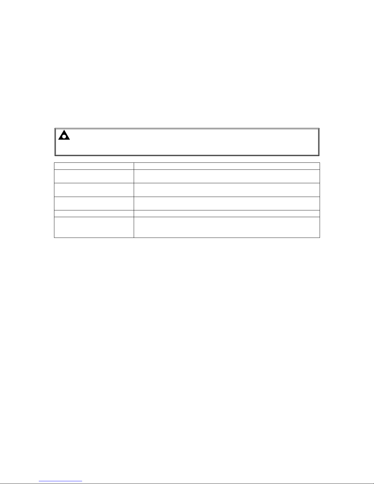
Cable Type Two core screened twisted pair
Cable Characteristic
Impedance
120Ω
Recommended Cable Belden 9841
Belden 9271
Maximum Cable Length 1200m (¾ mile) when using Belden 9841 or direct equivalent.
600m (666 yds) when using Belden 9271 or direct equivalent.
RS485 Topology “Daisy Chain” Bus with no stubs (spurs)
RS485 Termination
120Ω. Termination resistor must be fitted externally to the ‘first’ and
‘last’ expansion module by the customer as required by the RS485
specification.
Page 15
Specifications
15
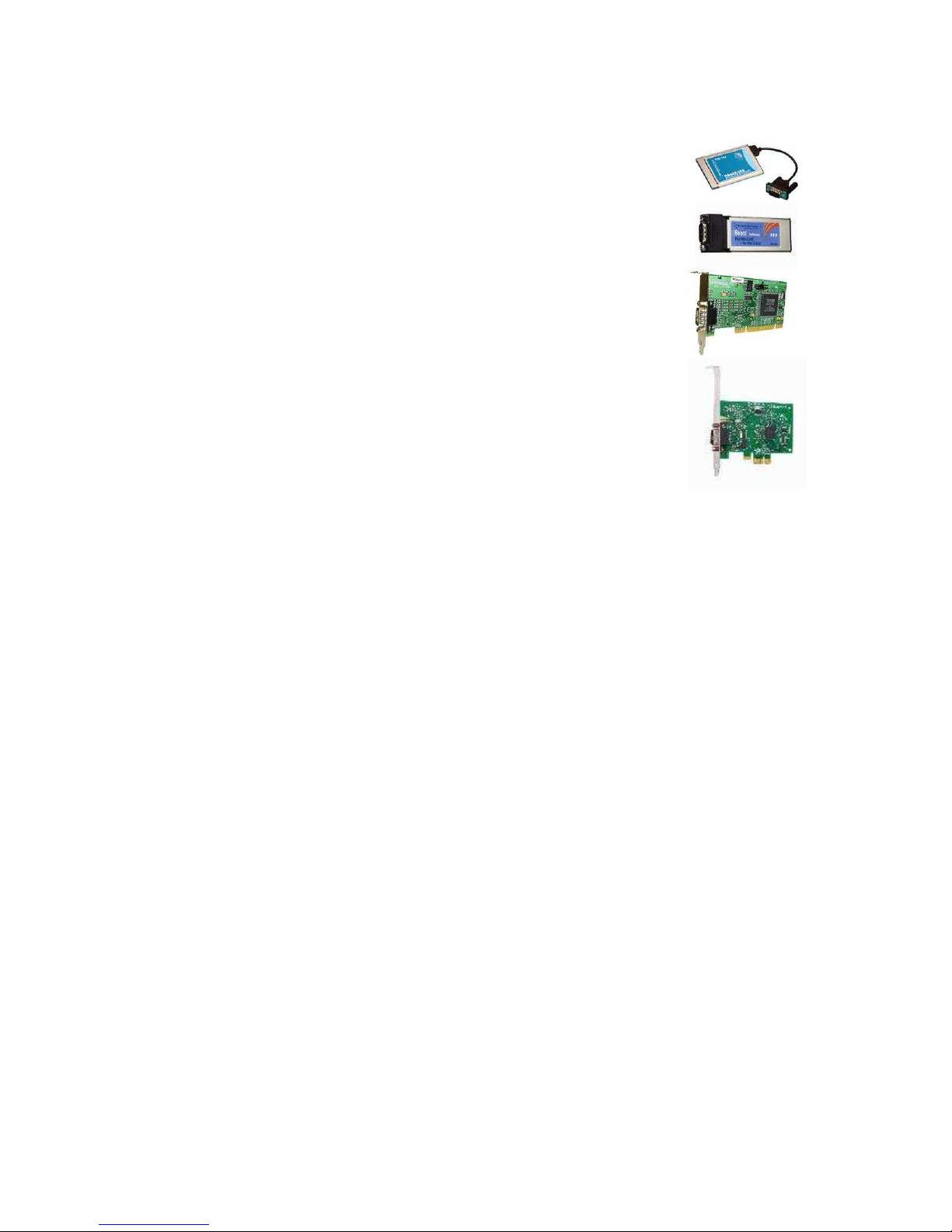
3.5.2.1 RECOMMENDED RS485 EXPANSION FOR DESKTOP AND LAPTOP PC’S
• Brainboxes PM154 PCMCIA RS485 card (for laptops PCs)
Set to ‘Half Duplex, Autogating” with ‘CTS True’ set to ‘enabled’
• Brainboxes VX-023 ExpressCard 1 Port RS422/485 (for laptops and
nettop PCs)
• Brainboxes UC320 PCI Velocity RS485 card (for desktop PCs)
Set to ‘Half Duplex, Autogating” with ‘CTS True’ set to ‘enabled’
• Brainboxes PX-324 PCI Express 1 Port RS422/485 (for desktop PCs)
Supplier:
Page 16

Specifications
16
3.7 DIMENSIONS AND MOUNTING
Parameter
Comment
Cabinet type Custom cabinet for indoor use only
Overall size
(see below for diagram)
165 mm x 305 mm x 110 mm
(6.5” x 12” x 4.3”)
Material: Sheet steel enclosure of all-round solid construction
Surface finish: Powder-coated black
Protection category:
IP20
NEMA 1
Weight
3.2 kg
(7 lb 1 oz)
Mounting type Wall mounting
Mounting holes
Diameter 6 mm (0.2”)
63 mm x 284 mm (3.4” x 11.2”) centres
Operating Temperature
-30 °C to +85 °C with deratings
(-22 °F to +185 °F with deratings)
Measurements in mm
Page 17

Specifications
17
3.8 APPLICABLE STANDARDS
BS 4884-1
This document conforms to BS4884-1 1992 Specification for
presentation of essential information.
BS 4884-2
This document conforms to BS4884-2 1993 Guide to content.
BS 4884-3
This document conforms to BS4884-3 1993 Guide to presentation.
BS EN 60068-2-1
(Minimum temperature)
-30°C (-22°F)
BS EN 60068-2-2
(Maximum temperature)
+85°C (185°F)
BS EN 60950
Safety of information technology equipment, including electrical
business equipment.
BS EN 61000-6-2
EMC Generic Immunity Standard (Industrial).
BS EN 61000-6-4
EMC Generic Emission Standard (Industrial).
BS EN 60529
(Degrees of protection
provided by enclosures)
IP20
Protected against penetration by solid objects with a diameter of more
than 12 mm. Fingers or similar objects prevented from approach.
No protection against water
UL508
NEMA rating
Enclosure type 1
Provides a degree of protection against contact with the enclosure
equipment and against a limited amount of falling dirt
UK WEEE
REGULATIONS
Producer Registration Number WEE/BE0052TQ
In line with our policy of continual development, Deep Sea Electronics, reserve the right to change spec if ic ation with out n otic e.
Page 18
Installation
18
4 INSTALLATION
The DSE battery charger is fit-and-forget. It can be permanently connected to the supply and the load,
with no requirement to disable the charger during times of heavy load (such as engine cranking).
4.1 BATTERY SUITABILITY
The charger is factory set by DSE to suit Lead Acid batteries but can be adjusted to suit other battery
types using the Configuration Suite PC Software.
Care should be taken to ensure the batteries connected to the charger are of the correct ‘technology’
to suit the setting of the charger.
NOTE: Ensure any Standing Load (loads connected to the battery charger other than the
battery) are less 75% of the battery charger configured rating. This helps to ensure the charger
correctly detects the battery charge state.
Page 19
Installation
19
4.2 USER CONNECTIONS
Parameter
Comm
ent
Connection type Screw terminal, rising clamp, no internal spring
Min cable size 0.5mm² (AWG 20)
Max cable size 2.5mm² (AWG 14)
Recommended AC fuse
230V AC Input
110V AC Input
DSE9461 24V/12V 10A charger
DSE9460 24V/12V 5A charger
3.5A anti-surge
2.0A antisurge
6.3A anti-surge
3.5A anti-surge
4.2.1 BATTERY CHARGER
DANGER OF DEATH: LIVE PARTS exist within the enclosure. The enclosure cover must
not be removed when connected to an AC supply.
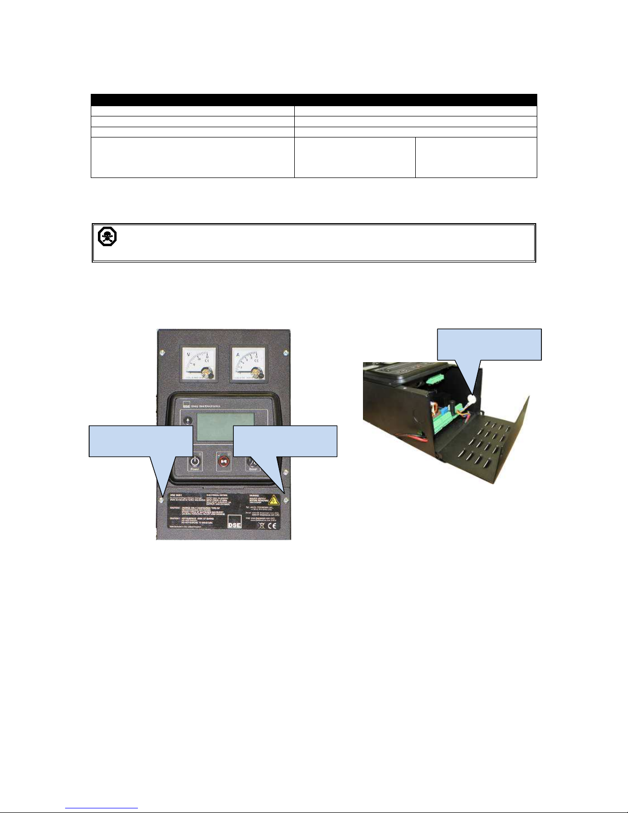
Battery Charger connections are available by removing the screws identified below and hinging the
cover down.
‘Push Outs’ are available on the side of the charger case to enable the installer to fit rubber grommets
to facilitate cable entry.
Cover hinged open
Remove the two
cover screws
Remove the two
cover screws
Cable access hole
Page 20
Installation
20
4.2.1.1 CONNECTOR A
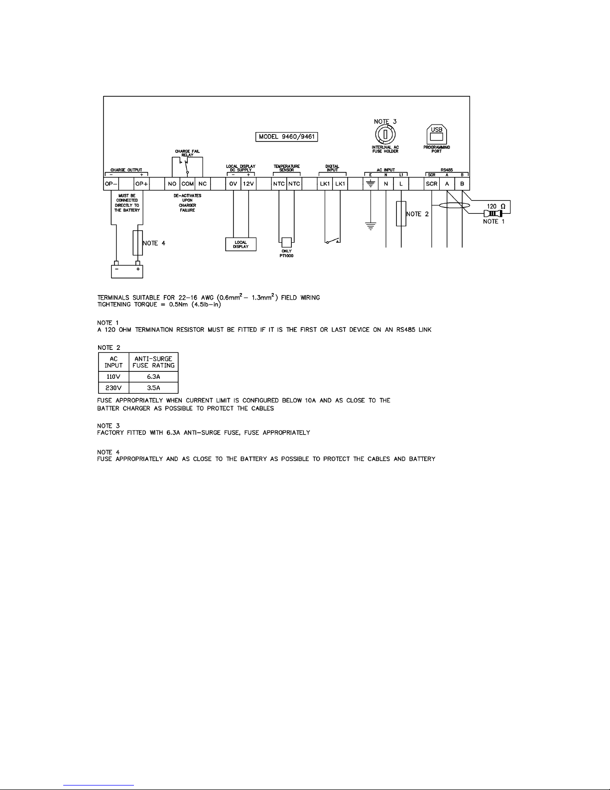
NOTE: - Connection from battery charge must be directly connected to the battery.
Terminal
Function
Recommended size
Comments
Load negative 1mm² (AWG 16) Battery negative terminal
Load Positive 1mm² (AWG 16) Battery positive terminal
4.2.1.2 CONNECTOR B / C
NOTE: Screened 120ΩΩΩΩ impedance cable specified for use with RS485 must be used for the
RS485 link.
DSE stock and supply Belden cable 9841 which is a high quality 120ΩΩΩΩ impedance cable
suitable for RS485 use (DSE part number 016-030)
Terminal
Function
Recommended size
Comments
0V
Supply for a remote
(locally fitted)
DSE2541 display
1mm² (AWG 16)
Do not connect to these terminals on
variants with LCD displays
(9460-01, 9460-02, 9461-01, 9461-02)
12V 1mm² (AWG 16)
SCR RS485 screen N/A
Use only 120Ω RS485 approved cable
B RS485 +ve 0.5mm² (AWG20)
A RS485 -ve 0.5mm² (AWG20)
LK
Connect together to
activate Digital Input
0.5mm² (AWG20)
Function Configurable using DSE
Configuration Suite PC Software
LK 0.5mm² (AWG20)
NTC
PT1000 connection
terminals
0.5mm² (AWG20)
Use only PT1000
NTC 0.5mm² (AWG20)
N/C
Fault relay Normally
Closed terminal
0.5 mm² (AWG 22)
De-energises under Fault Conditions
Common
Fault relay
Common Terminal
0.5 mm² (AWG 22)
N/O
Fault relay Normally
Open terminal
0.5 mm² (AWG 22)
4.2.1.3 CONNECTOR D
CAUTION: Ensure Earth Terminal is connected to Battery negative (for negative earth
systems) or Battery positive (for positive earth systems)
Where no system earth exists, Earth Terminal must be connected to battery negative
Parameter
Comment
Recommended AC fuse
230V AC Input
110V AC Input
DSE9461 24V/12V 10A charger
DSE9460 24V/12V 5A charger
3.5A anti-surge
2.0A antisurge
6.3A anti-surge
3.5A anti-surge
Terminal
Function
Recommended Size
L AC Live 1mm² (AWG 16)
N AC Neutral 1mm² (AWG 16)
Earth 1mm² (AWG 16)
Page 21
Installation
21
4.2.2 TYPICAL CONNECTION DIAGRAM
Page 22
Installation
22
4.3 DSE2541 ENCLOSURE MOUNTED DISPLAY MODULE
NOTE: LCD display is fitted only to the following model numbers : 9460-01, 9460-02, 946101, 9461-02
NOTE: Where factory fitted to the enclosure, the DSE2541-01 must not be removed.
Should an external, remote display be required, use DSE Part Number 2541-02 suitable for
remote location up to 1.2km from the host battery charger.
NOTE: These connections are made by the DSE factory and are included for information
only.
Terminal
Function
Recommended Size
Comments
1 Plant Supply Negative 1mm² (AWG16)
2 Plant Supply Positive 1mm² (AWG16)
3 RS485 (Screen) N/A
Use only 120Ω RS485 approved
cable
4 RS485 (B) 0.5mm² (AWG20)
5 RS485 (A) 0.5mm² (AWG20)
NOTE: Screened 120ΩΩΩΩ impedance cable specified for use with RS485 must be used for the
RS485 link.
DSE stock and supply Belden cable 9841 which is a high quality 120ΩΩΩΩ impedance cable
suitable for RS485 use (DSE part number 016-030)
Page 23
Operation
23
5 INDICATIONS
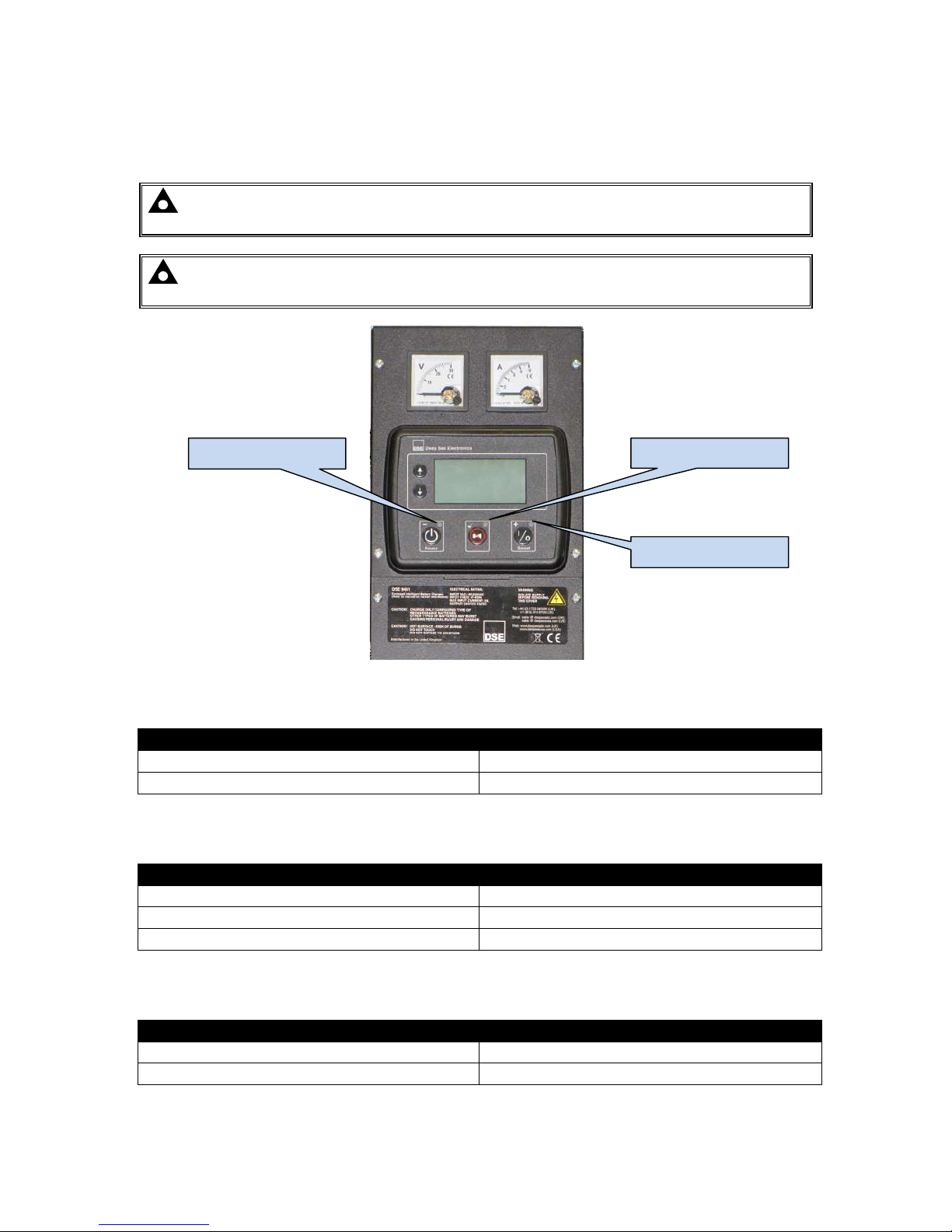
5.1 LCD DISPLAY
NOTE: LCD display is fitted only to the following model numbers : 9460-01, 9460-02, 946101, 9461-02
NOTE: For details of controls and LCD indication, see the section entitled Operation
elsewhere in this document.
5.1.1 CHARGER STATUS
Condition
LED State
Charger off OFF
Charger on Constant Red
5.1.2 FAULT STATUS
Condition
LED State
No Fault OFF
Warning Fault Constant Red
Shutdown Fault Flashing Red
5.1.3 BOOST MODE
Condition
LED State
No Boost OFF
In Boost Mode Constant Red
Charger status LED Fault status LED
Boost Mode LED
Page 24
Operation
24
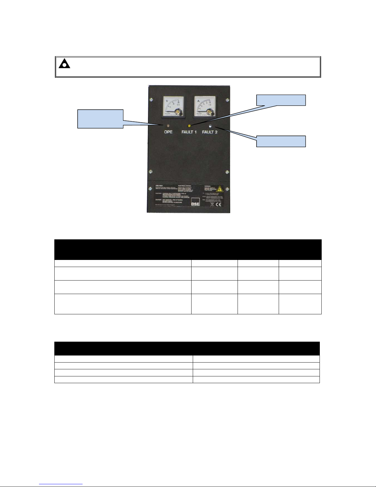
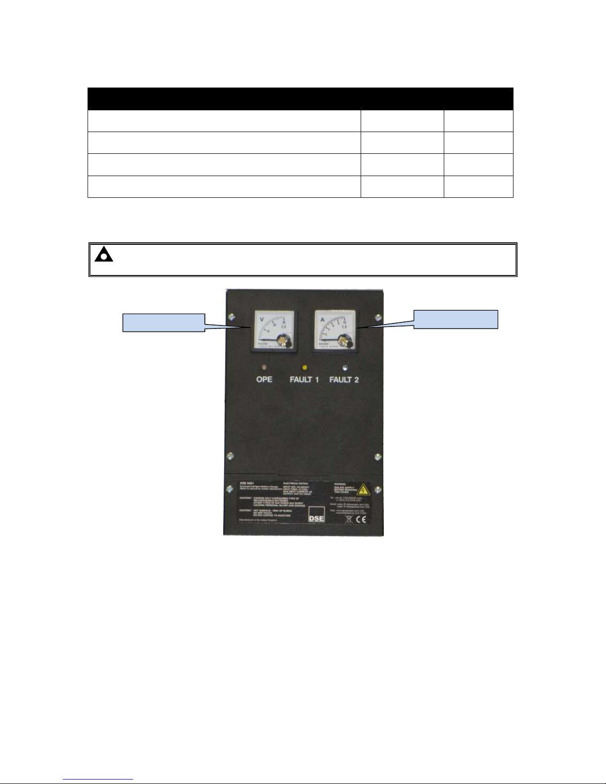
5.2 ENCLOSURE MOUNTED LEDS
NOTE: - Enclosure mounted LED indicators are fitted only to the following model
numbers : 9460-03, 9460-04, 9461-03, 9461-04
5.2.1 STATUS
Condition
LED DESIGNATION
OPE
Yellow/Green
FAULT 1
Yellow
FAULT 2
Red
Charger Off Off Off Off
Battery not Detected (Battery Detection Mode)
Green
Flashing
Yellow
Flashing
Red
Flashing
Battery Connected (Battery Detection Mode)
Green
Constant
Yellow
Constant
Red
Constant
Not Charging
(Charger is operating correctly but the ouput has
been disconnected from the battery)
Off
Yellow
Constant
Red
Constant
5.2.2 CHARGE MODE
Mode
LED DESIGNATION
OPE
Bulk Charge in progress Yellow Constant
Absorption Charge in progress Yellow Flashing
Float Charge in Progress Green Constant
Storage Charge in Progress Green Flashing
OPE LED
(Operation)
FAULT 2 LED
FAULT 1 LED
Page 25
Operation
25
5.2.3 FAULT CONDITIONS
Condition
LED DESIGNATION
FAULT 1
FAULT 2
High Output Voltage (DC)
Red
Constant
Off
High / Low Input Voltage (AC) or High Output Current (DC)
Red
Flashing
Off
High Ambient / Charger Temperature, High Battery
Temperature (if enabled)
Off
Red
Constant
Short Circuit/ Reverse Polarity (DC Output Connection) Off
Red
Flashing
5.3 ENCLOSURE MOUNTED ANALOGUE METERS
NOTE: - Enclosure mounted analogue meters are fitted only to the following model
numbers : 9460-02, 9460-03, 9461-02, 9461-03
DC Voltmeter
DC Ammeter
Page 26
Operation
26
6 OPERATION
The DSE battery charger can be used as a battery charger, DC power supply, or both at the same
time. For instance, the unit can be used to power the generator control panels and charge the panel
batteries or starter batteries at the same time.
With no AC input to the charger, the Charge fail relay is de-energised. This can be used to provide
indication of charger failure which operates upon mains supply AC supply f ailure or battery charging
failure.
When a suitable AC supply is connected, operation of the unit will depend upon the load connected to
the unit’s output terminals :
Battery connected – The charging operation will begin (Charge mode)
No Battery connected – The output voltage will be enabled. (PSU mode)
Reverse connected battery – The charger will remain in charge fail mode.
Short circuit – The charger will remain in charge fail mode.
AC under/over voltage – The charger will remain in charge fail mode.
DC over current/voltage – The charger will remain in charge fail mode.
Over temperature - The charger will remain in charge fail mode.
Battery Charger Failure - The charger will remain in charge fail mode.
Depending upon the model variant, the battery charger can be operated using either the remote or
enclosure mounted DSE2541.
Operation of the LCD display module is covered later in this section.
6.1 OPERATING MODES
6.1.1 PSU MODE
If no battery is connected to the output terminals, the DSE battery charger will operate as a DC power
supply only, current limit is f actory set. See the section entitled Specification elsewhere in this manual
for output specifications.
6.1.2 CHARGE MODE
NOTE: Ensure any Standing Load (loads connected to the battery charger other than the
battery) are less 75% of the battery charger configured rating. This helps to ensure the charger
correctly detects the battery charge state.
Constant Voltage
The DSE battery charger operates in Constant voltage current limited mode.
The charger output voltage is maintained at a constant level to allow the battery to charge while the
load does not exceed the maximum rating of the charger.
Once the battery is fully charged, the battery charger switches to ECO-POWER mode. This is a low
power use standby mode.
Current Limit
If the load on the battery charger (battery charge demand+standing load) exceeds the maximum
current rating of the charger, the charging current is limited to the maximum rating of the charger and
the voltage is reduced.
The voltage will rise to the rated voltage again once the load drops below the maximum rating of the
charger.
Page 27

Operation
27
Charging time
Charge time is often of little consequence when the battery is used in a standby operation. An
example of this is when the battery is used to supply the starting system of a diesel generator. During
normal operation, the battery is at full capacity and the battery charger is used to maintain the float
voltage of the battery. The battery is only drained when the generator is called to start. As the
generator has a DC charging alternator fitted, the battery is quickly recharged when the generator is
running. Should the generator stop before the battery is fully recharged, the battery charger continue
sto recharge the battery until it is fully charged.
Typically a battery will charge from flat to 80% capacity in 16hrs when when charged at C/10.
For example charging a 50Ah battery for 16hrs at 5A will charge the battery to 80% of its full capacity.
Remember to take into account any other standing load such as control panel requirements when
calculating how much power is ‘left’ to charge the battery.
6.1.3 BOOST MODE
Boost mode is operated automatically or by activation of the digital input (if configured to perform this
function). This raises the battery charger voltage to the boost voltage setting. It will stay in boost mode
until the current drawn from the charger drops below 75% of the rated output, it will then go into a
timed run-on charge.
The battery charger will go back into boost mode, if the charge voltage is detected to drop below 1.8V
per battery cell.
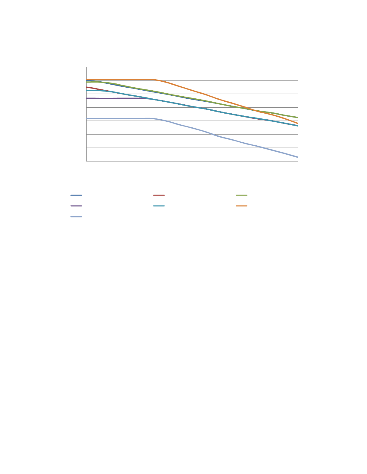
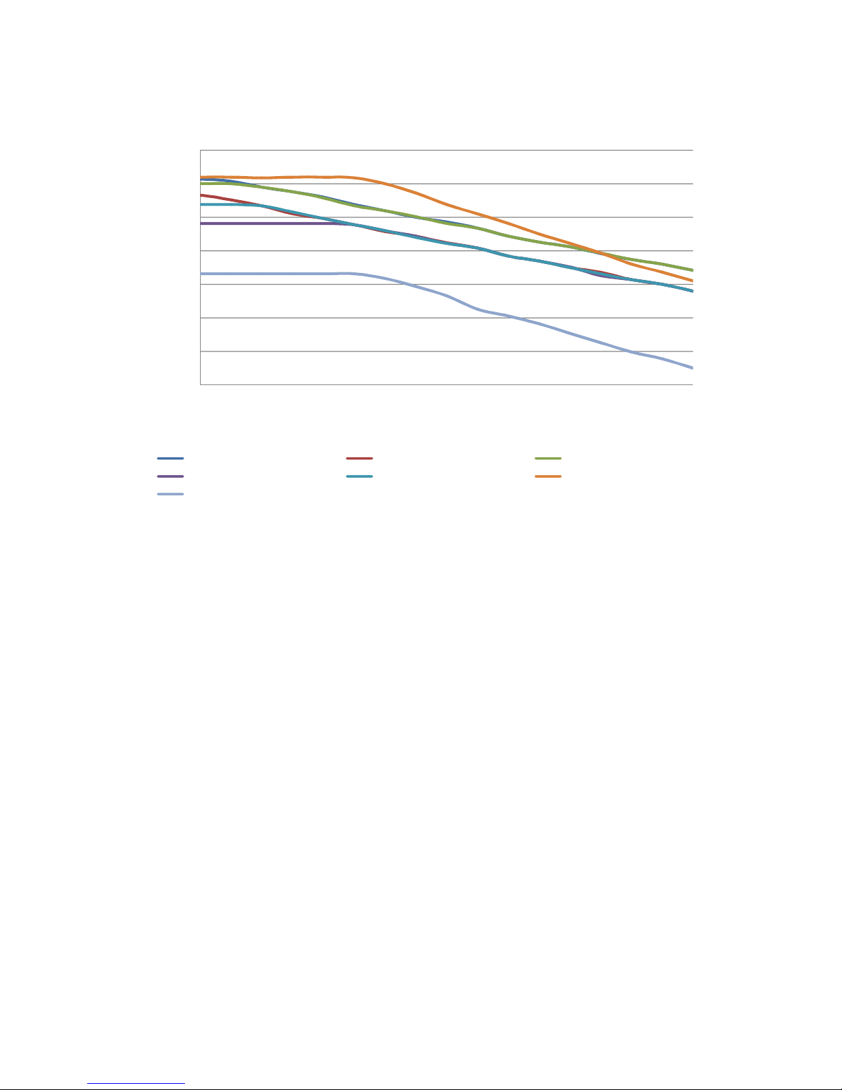
6.1.4 TEMPERATURE COMPENSATION
If temperature compensation is enabled through configuration, and remote temperature sensor is
connected, the output voltage automatically varies by a configured mV per cell per 1°C deviation from
20°C, within the range of -20°C to 60°C. Increasing temperature give decreasing outputs and
decreasing temperatures give increasing outputs.
The battery temperature will be measured by a temperature sensor (2 wire PT1000 sensor) which will
be placed on the battery
Page 28
Operation
28
23
24
25
26
27
28
29
30
-20 -10 0 10 20 30 40 50 60
Voltage (Volts)
Temperature (ºC)
Battery Temperature Compensation
(Configured to 24V)
Calcium
Lead Acid Antimony
VRLA
-
AGM
VRLA
-
AGM
Wet (Vented) Lead Acid
NiCd 10/20 Cell
NiCd-9/18 Cell
Page 29
Operation
29
11.5
12
12.5
13
13.5
14
14.5
15
-20 -10 0 10 20 30 40 50 60
Voltage (Volts)
Temperature (ºC)
Battery Temperature Compensation
(Configured to 12V)
Calcium
Lead Acid Antimony
VRLA
-
AGM
VRLA-GEL Wet (Vented) Lead Acid NiCd 10/20
NICd 9/18
Page 30
Operation
30
6.2
OPERATION OF LCD DISPLAY
NOTE: LCD display is fitted only to the following model numbers : 9460-01, 9460-02, 9461-
01, 9461-02
NOTE: An external remotely connected LCD display can be added to models without the
enclosure mounted display. DSE Part Number 2541-02.
6.2.1 BACKLIGHT
The LCD backlight is ON while the module is powered and flashes up detection of an alarm condition.
6.2.2 LED
The Display Module has three integral LEDs to show operation status and fault conditions. Full details
are contained in the section entitled Indications elsewhere in this document.
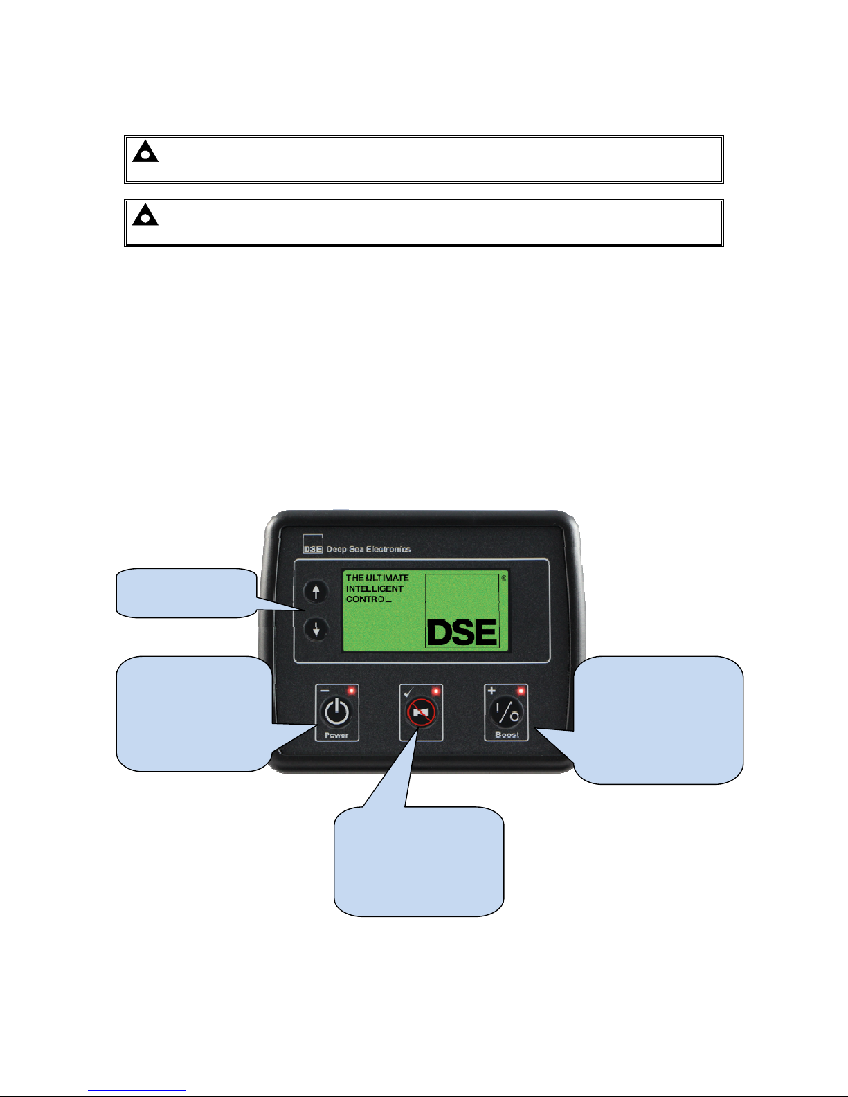
6.2.3 CONTROL BUTTONS
The LCD display has five control buttons :
Display Navigation
buttons
Toggles the power of
the battery charger.
Also used for the
decrement function
(-) in the Front Panel
Editor.
Toggles the boost
mode on the battery
charger.
Also used for the
increment function (+)
in the Front Panel
Editor.
Requests an alarm
clear on the battery
charger.
Also used for entering
and exiting the Front
Panel Editor ().
Page 31
Operation
31
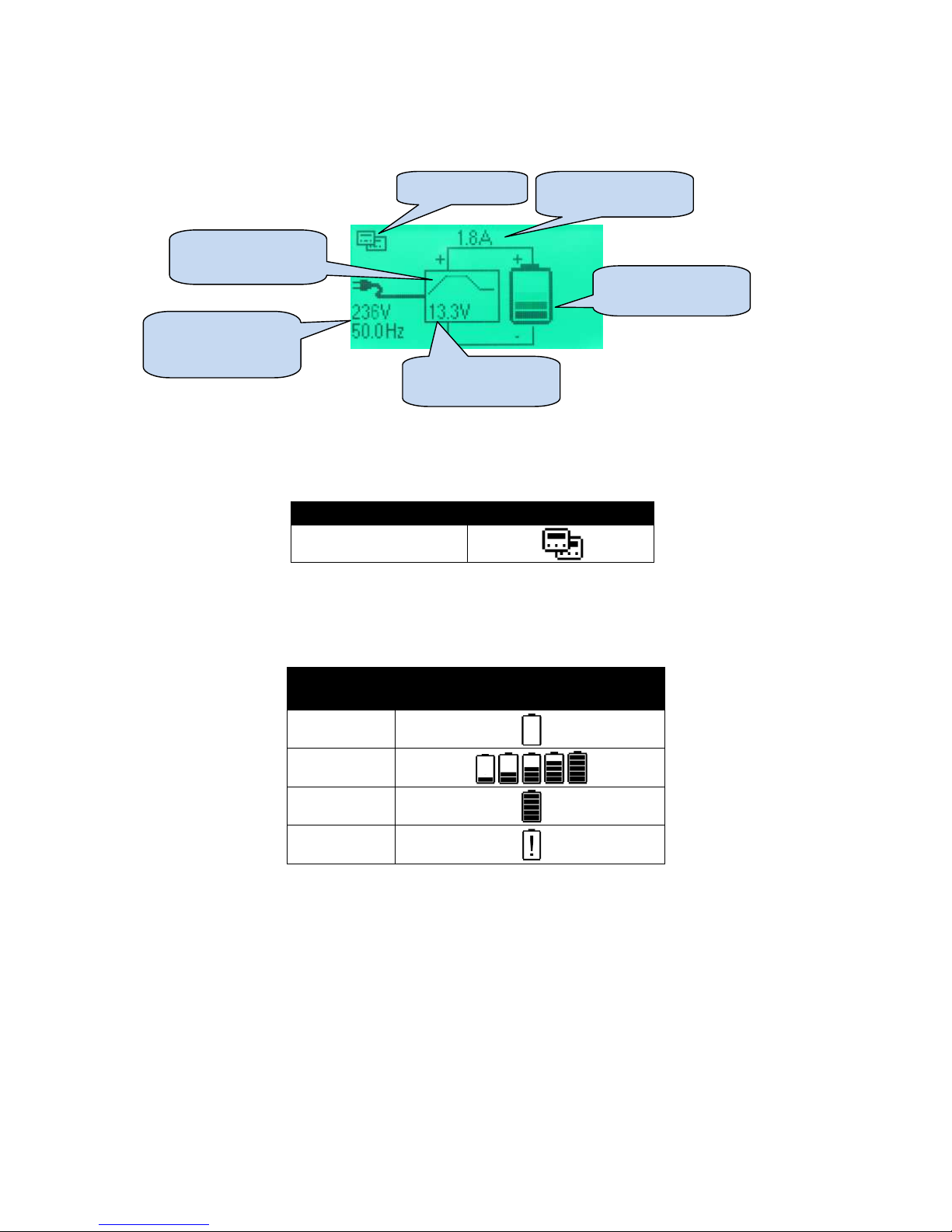
6.2.4 SUMMARY SCREEN
The Summary Screen is initially displayed when the charged is turned on, and subsequently after a
period of inactivity.
6.2.5 LINK ICON
The link icon indicates a successful link to the battery charger over the RS485 link. If there is no link
active the icon is not shown.
Alarm
Condition
Icon
RS485 Active
6.2.6 BATTERY ICON
The battery icon indicates the current state of charging.
Battery State Icon graphic
Not Charging
Charging
animation
Floating
Fault
Battery charge
current
Battery icon to
show charge state
Charge graphic to
show charge mode
Mains (utility)
supply
instrumentation
Battery charge
voltage
Link icon
Page 32
Operation
32
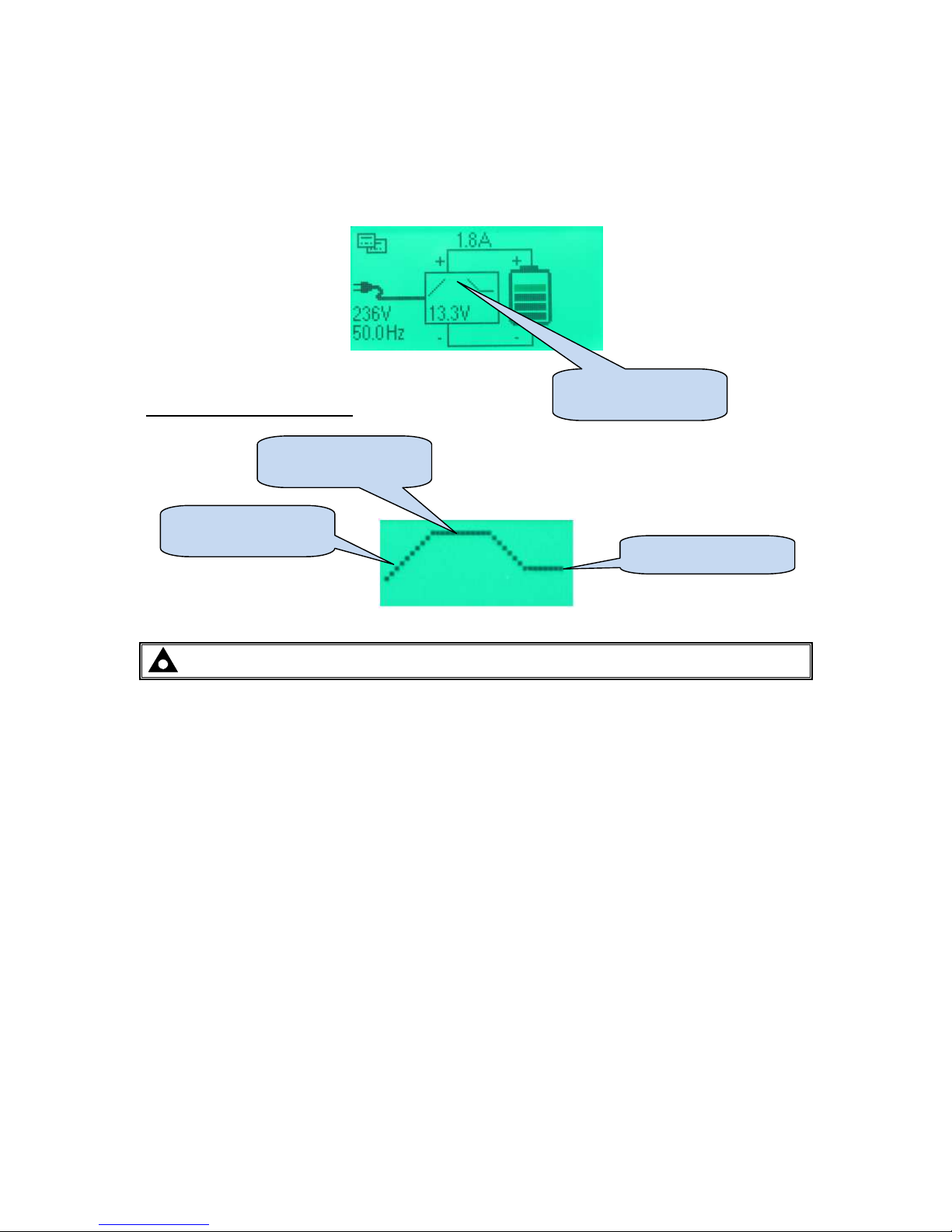
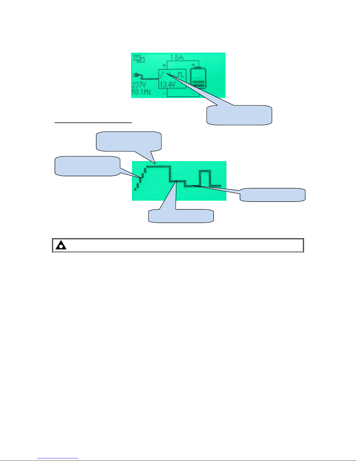
6.2.7 CHARGE GRAPHIC
The LCD shows the charge graphic to show the selected charge curve. The currently active mode is
shown flashing in the module display.
6.2.7.1 THREE STAGE CHARGE PROFILE
Detail of charge curve display
NOTE: - A description of each charge mode is given earlier in this manual.
Flashing to show
charge mode
Boost (Bulk) charge
mode
Absorption charge
mode
Float charge mode
Page 33
Operation
33
6.2.7.2 FOUR STAGE CHARGE PROFILE
Detail of charge curve display
NOTE: - A description of each charge mode is given earlier in this manual.
Flashing to show
charge mode
Boost (Bulk) charge
mode
Absorption charge
mode
Storage charge mode
Float charge mode
Page 34
Operation
34
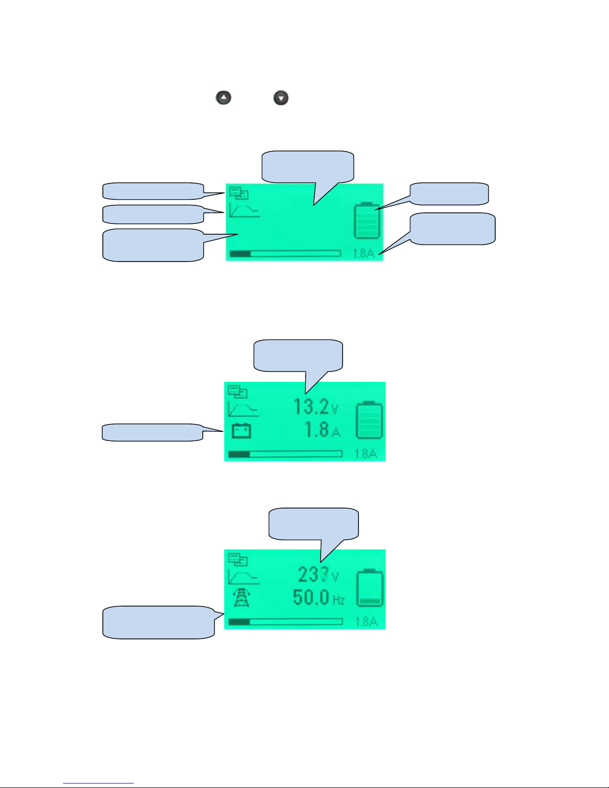
6.2.8 VIEWING THE INSTRUMENTATION
Press the navigation buttons (up) and (down) to cycle through the available instrumentation
screens.
All instrumentation screens have the following common icons :
An icon is used to show the meaning of the currently visible screen as shown in the following
sections.
6.2.8.1 BATTERY
6.2.8.2 MAINS
Mains (utility) screen
icon
Mains (utility)
instrumentation
Battery screen icon
Link icon
Charge graphic
Instrumentation
screen type icon
Instrumentation
area
Battery icon
Battery charge
current
Battery
Instrumentation
Page 35
Operation
35
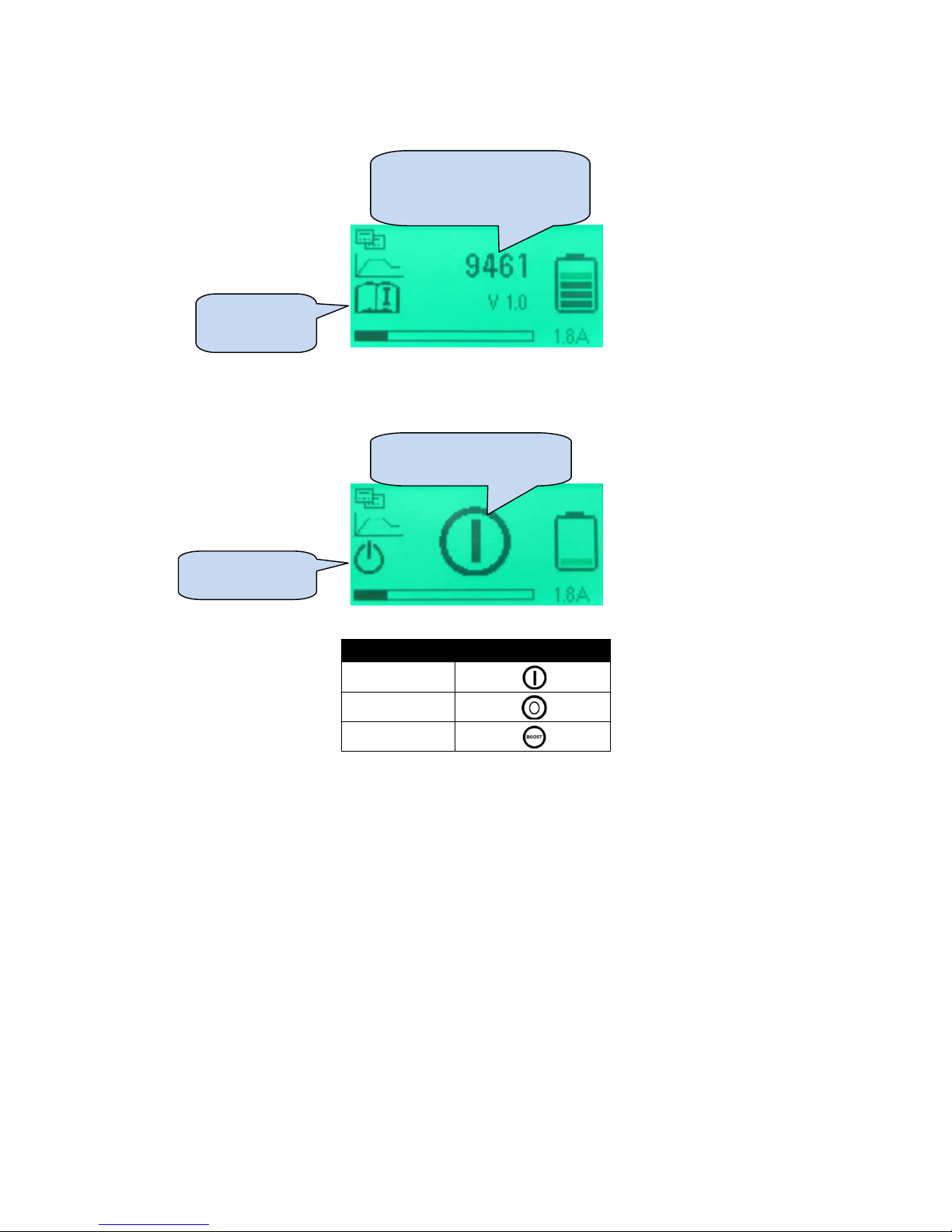
6.2.8.3 PRODUCT INFO
6.2.8.4 CONTROL MODE
Control State
Icon displayed
On
Off
Boost
Product info
screen icon
Shows model and firmware
version of currently
connected battery charger.
Control mode
screen icon
Shows current operating
mode
Page 36
Operation
36
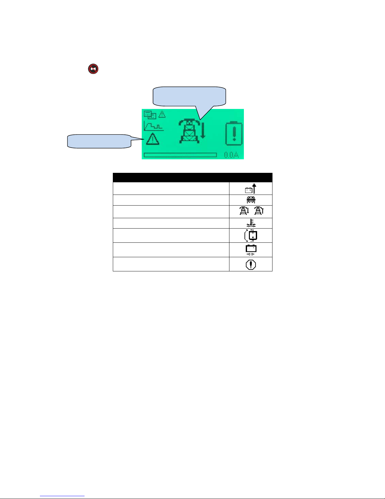
6.2.8.5 ALARMS
When a new alarm is detected, the LCD displays the alarm screen and the LCD backlight flashes.
Press the () button to accept the alarm, exit the alarm screen and return to the summary
screen.
Alarm condition
Icon displayed
DC Over Volts
DC Over Current
AC Under or Over Volts
/
Over Temperature
Short Circuit or Reverse polarity
Battery open circuit
Battery Charger Failure
Alarm screen icon
Shows current alarm
condition
Page 37
Operation
37
6.3 FRONT PANEL EDITOR
6.3.1 ACCESSING THE FRONT PANEL EDITOR
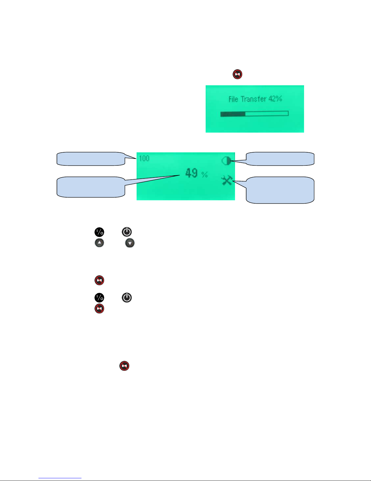
The front panel editor (FPE) is accessed by pressing and holding the () button.
During the transfer of the configuration file from the
battery charger to the display module, the File Transfer
progress screen is displayed.
When the transfer is completed the first parameter is
displayed:
The first parameter is displayed.
6.3.2 SELECTING A PARAMETER
• Press (+) or (-) to change between parameter pages (listed overleaf).
• Press (up) or (down) to cycle through the available parameters (listed overleaf).
6.3.2.1 EDITING A PARAMETER
• Press () to edit a parameter when it is being viewed on the screen. The value flashes
to show edit mode is in progress.
• Press (+) or (-) to change the parameter to the required value.
• Press () to save the currently selected value. The value ceases flashing to show
editing is complete.
Other parameters can now be selected and edited in the same manner.
6.3.2.2 EXITING THE EDITOR
• Press and hold () to exit the editor.
• The File Transfer screen shown progress as the configuration is uploaded from the display
module to the battery charger.
Parameter number
Parameter value
(current setting)
Parameter icon
Editor icon (shown
when the editor is in
use)
Page 38
Operation
38
6.3.3 FRONT PANEL EDITOR PARAMETERS
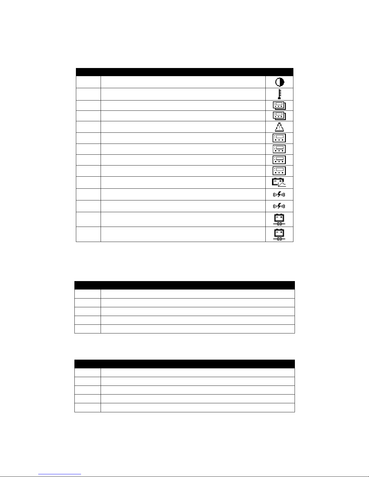
6.3.3.1 PAGE 1 – MISCELLANEOUS
Index
Configuration item
Icon
100 Contrast
101 Temperature Units
102 Slave ID
103 Baud Rate
104 Enable Alarm Splash Screen
105 Page Timout Screen
106 Page Timeout
107 Sleep Mode Timeout
108 Digital Input Function
109 Battery Voltage
110 Battery Self Test Enabled
111 Battery Self Test Timer
112 Battery Detection Enabled
113 Battery Detection Rate
Parameter 105 – Page Timeout Screen selects the ‘main’ display screen. This is the screen that is
displayed after a period of inactivity (no buttons are pressed for the duration of Page Timeout
(parameter 106). It has the following possible selections :
Value
Function
0 Summary Page
1
Battery Information.
2
Mains Information.
3
Product Information.
4
Control Mode
Parameter 108 – Digital Input Function has the following possible selections :
Value
Function
0 Lamp Test
1
Charger Off
2
Enable Battery
Detection
3
Manual Boost
4
Switch Voltage Mode
(12V / 24V)
Page 39
Operation
39
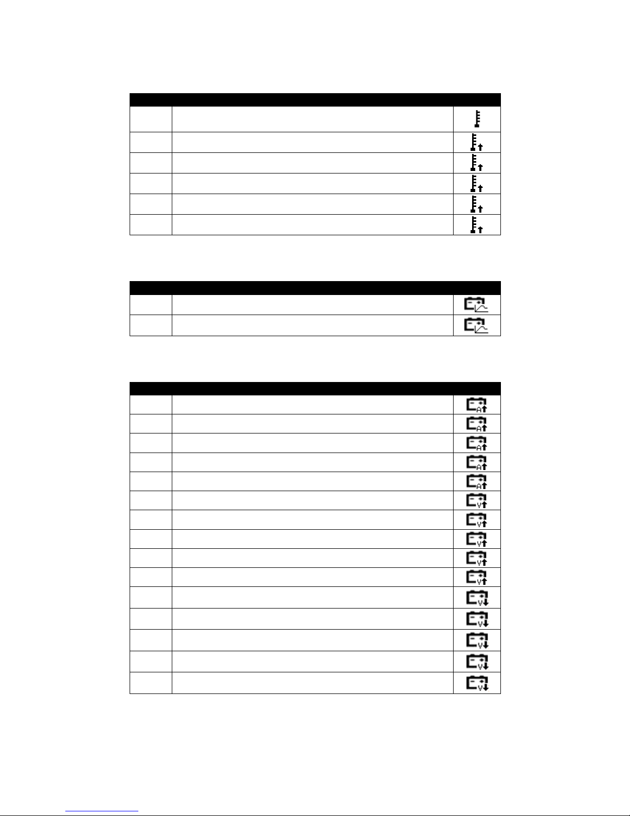
6.3.3.2 PAGE 2 – BATTERY TEMPERATURE
Index
Configuration item
Icon
200 Battery Temperature Sensor Enable
201 Battery Temperature Warning Alarm Enable
202 Battery Temperature Warning Alarm Trip
203 Battery Temperature Warning Alarm Delay
204 Battery Temperature Warning Return
205 Battery Temperature Warning Return Delay
6.3.3.3 PAGE 3 – BATTERY OPTIONS
Index
Configuration item
Icon
300 Battery Current Limit
301 Battery Profile Stages
6.3.3.4 PAGE 4 – ALARMS
Index
Configuration item
Icon
400 Over Current Alarm Enable
401 Over Current Alarm Trip
402 Over Current Alarm Trip Delay
403 Over Current Alarm Return
404 Over Current Alarm Return Delay
405 Over Voltage Alarm Trip Enable
406 Over Voltage Alarm Trip
407 Over Voltage Alarm Trip Delay
408 Over Voltage Alarm Return
409 Over Voltage Alarm Return Delay
410 Under Voltage Alarm Trip Enable
411 Under Voltage Alarm Trip
412 Under Voltage Alarm Trip Delay
413 Under Voltage Alarm Return
414 Under Voltage Alarm Return Delay
Page 40
Operation
40
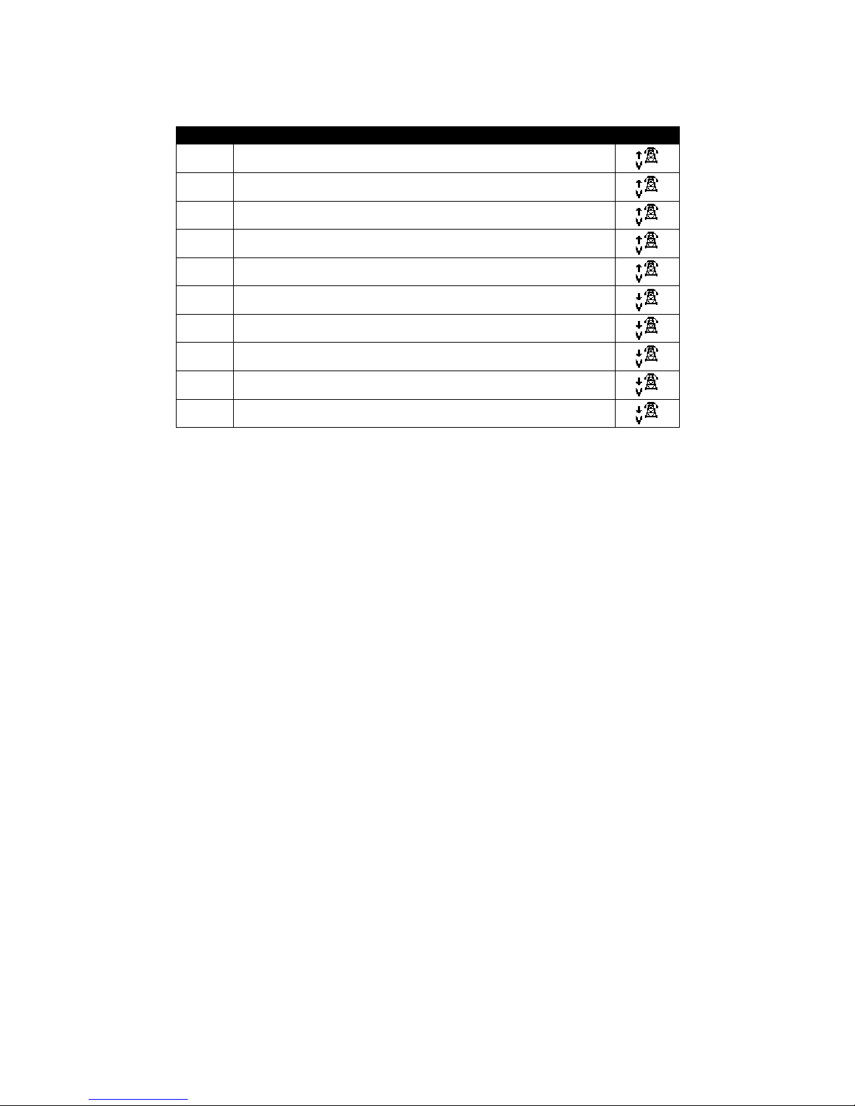
6.3.3.5 PAGE 5 – MAINS
Index
Configuration item
Icon
500 Mains Over Voltage Enable
501 Mains Over Voltage Alarm Trip
502 Mains Over Voltage Alarm Trip Delay
503 Mains Over Voltage Alarm Return
504 Mains Over Voltage Alarm Return Delay
505 Mains Under Voltage Enable
506 Mains Under Voltage Alarm Trip
507 Mains Under Voltage Alarm Trip Delay
508 Mains Under Voltage Alarm Return
509 Mains Under Voltage Alarm Return Delay
Page 41
Operation
41
7 MODBUS
The DSE Battery Charger supports the modbus RTU protocol over half-duplex RS485
communications.
RS485
parameter
Setting
Start Bits 1
Data Bits 8
Parity None
Stop Bits 2
Baud Rate Configurable using DSE Configuration Suite PC Software
(1200, 2400/ 4800, 9600, 19200, 28800, 38400, 57600, 115200)
Factory setting : 9600
Modbus Slave ID Configurable using DSE Configuration Suite PC Software
(1-247)
Factory Setting : 10
7.1 READING VALUES
Values must bre read using Modbus Function Code 3 – Read Multiple Registers.
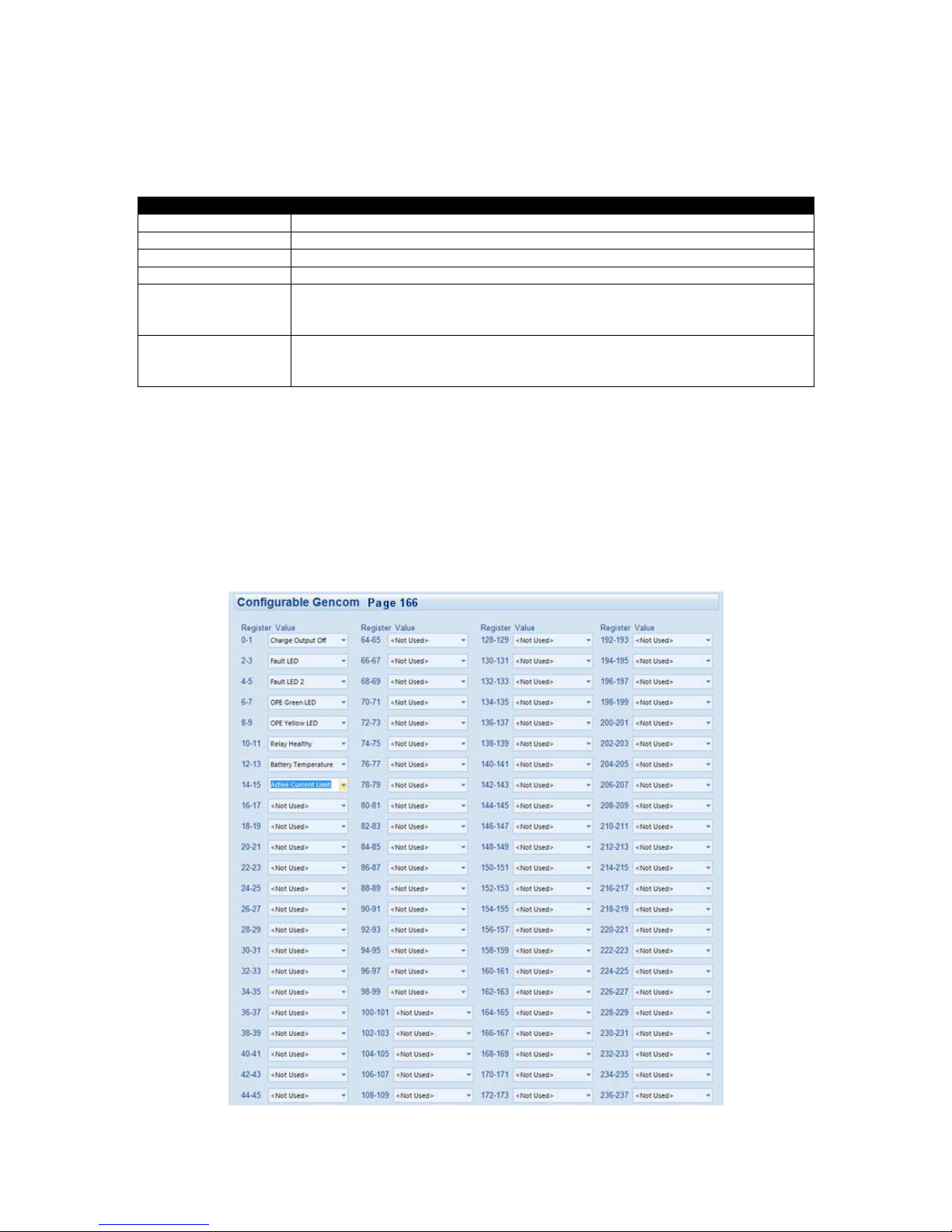
Using the DSE Configuration Suite PC Software, modbus registers are defined by the system
designer in modbus Page 166.
An example of customer configuration is shown below, the screen image is take from the SE
Configuration Suite PC Software.
Page 42
Operation
42
Modbus
parameter
Value
Modbus Register
Start
Address Page 166
Absolute HexaDecimal Address A600
Absolute Decimal Address 42496 (166 x 256).
NOTE: Some Legacy Modbus Master devices may require a suffix of
40,000 to the address, making the base address 82496.
NOTE: Some Modbus Master devices may require ‘1’ to be added to
the address.
Modbus Register
Size / Sign
32 bit, signed
Modbus Register
Type
Holding Registers
(modbus function code 3 supported)
7.2
WRITING VALUES
Writing values to the battery charger is used to perform functions below.
Two values must be written using the same write function.
Using Modbus Function Code 16 – Write Multiple Registers, write the required Control Key and One’s
Compliment of the Control key to the specified registers:
7.2.1 TOGGLE BOOST MODE
Writing this control key enables or disables boost mode. When in boost mode, the battery is charged
at the configured boost voltage.
Single Modbus Write using Modbus Function Code 16 – Write Multiple Registers
Address to write to
Control Key
One’s
Compliment
of Control Key
Decimal Address 4104 & 4105
(Hexadecimal 1008 & 1008)
35772 27963
7.2.2 TOGGLE CHARGER ON/OFF
Writing this control key enables or disables the charger’s DC output.
Single Modbus Write using Modbus Function Code 16 – Write Multiple Registers.
Address to write to
Control Key
One’s
Compliment
of Control Key
Decimal Address 4104 & 4105
(Hexadecimal 1008 & 1008)
35773 29762
Page 43

Operation
43
8 FAULT DIAGNOSIS
Nature of problem
Suggest
ion
The charger is not operating
Check that the incoming AC supply is correctly connected and within
limits and check the integrity of any external fuse that may be fitted.
Ensure the charger is not being operated above the maximum
temperature specification.
Charge fail relay
continuously operated
Check the connected load of the charger is not reverse connected or
short circuit.
Batteries fail to charge
Check the batteries using the battery manufacturers
recommendations.
Charge time is too long
Typically a battery will charge from flat to 80% capacity in 16hrs when
when charged at C/10.
For example charging a 50Ah battery for 16hrs at 5A will charge the
battery to 80% of its full capacity.
Remember to take into account any other standing load such as
control panel requirements when calculating how much power is ‘left’
to charge the battery.
Page 44

Maintenance, Warranty and Disposal
44
9 MAINTENANCE, SPARES, REPAIR AND SERVICING
The DSE battery chargers are designed to be Fit and Forget. As such, there are no user serviceable
parts. In the case of malfunction you should contact your original equipment supplier (OEM).
10 WARRANTY
DSE provides limited warranty to the equipment purchaser at the point of sale. For full details of any
applicable warranty, you are referred to your original equipment supplier (OEM).
11 DISPOSAL
11.1 WEEE (WASTE ELECTRICAL AND ELECTRONIC EQUIPMENT)
If you use electrical and electronic equipment you must store, collect, treat, recycle and dispose of
WEEE separately from your other waste.
Page 45

This Page is Intentionally Left Blank.
Page 46

This Page is Intentionally Left Blank.
Page 47
DSE
®
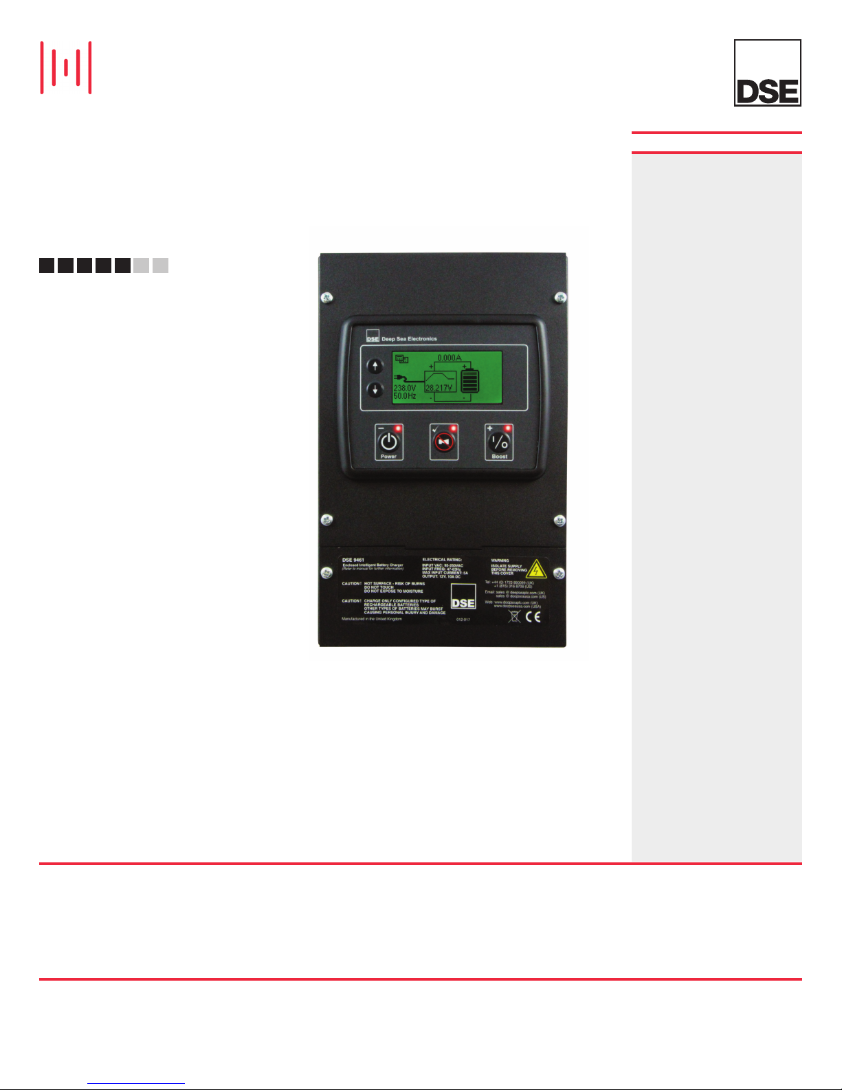
DSE9460/9461
ENCLOSED INTELLIGENT BATTERY CHARGER
5 AMP & 10 AMP, 12 VOLT & 24 VOLT OPTIONS
FEATURES
The DSE94xx series of metal
enclosed intelligent battery chargers
have been developed with safety,
usability, optimised battery
performance and maximum battery
lifetimes in mind.
The DSE94xx series can be used
directly from the box, relying on a
preconfigured lead/acid charging
curve and selected manually for
either 12V or 24V operation
(including a voltage trimming
potentiometer function). Alternatively
they can be connected via a USB to
a PC (using the free DSE PC
configuration suite software) and can
be configured with pre set charging
curves for different battery types.
The user also has the option of
configuring their own bespoke
charging curve for advanced battery
applications.
A comprehensive range of input and
output protections ensures a
continued safe charging
environment also enabling the use of
the charger as a power supply.
Higher charging / power supply
currents can be achieved by linking
together multiple chargers from this
series.
The chargers can be integrated into
an external system through modbus
RTU using RS485 as well as an
optional external remote LCD
display being available.
AVAILABLE 5 AMP VERSIONS
9460-01
9460-02
460-11
9
9460-12
AVAILABLE 10 AMP VERSIONS
9461-01
9461-02
9461-03
9461-04
461-11
9
9461-12
9461-13
9461-14
12v 5A (LCD)
12v 5A (LCD & Meters)
4v 5A (LCD)
2
24v 5A (LCD & Meters)
12v 10A (LCD)
2v 10A (LCD & Meters)
1
2v 10A (LED & Meters)
1
12v 10A (LED)
24v 10A (LCD)
24v 10A (LCD & Meters)
24v 10A (LED & Meters)
4v 10A (LED)
2
ENVIRONMENTAL TESTING STANDARDS
ELECTRO-MAGNETIC COMPATIBILITY
BS EN 61000-6-2
EMC Generic Immunity Standard for
the Industrial Environment
BS EN 61000-6-4
EMC Generic Emission Standard for
he Industrial Environment
t
TEMPERATURE
BS EN 60068-2-1
Ab/Ae Cold Test -30
BS EN 60068-2-2
Bb/Be Dry Heat +80 oC
Refer to de-rating curve in the DSE9000
*
Operator Manual
VIBRATION
BS EN 60068-2-6
Ten sweeps in each of three
major axes
Hz to 8 Hz at +/-7.5 mm,
5
8 Hz to 500 Hz at 2 gn
HUMIDITY
BS EN 60068-2-30
b Damp Heat Cyclic 20/55
D
t 95% RH 48 Hours
a
S EN 60068-2-78
B
ab Damp Heat Static 40
C
at 93% RH 48 Hours
HOCK
S
S EN 60068-2-27
B
Three shocks in each of three major axes
15 gn in 11 mS
o
C
o
C
o
C
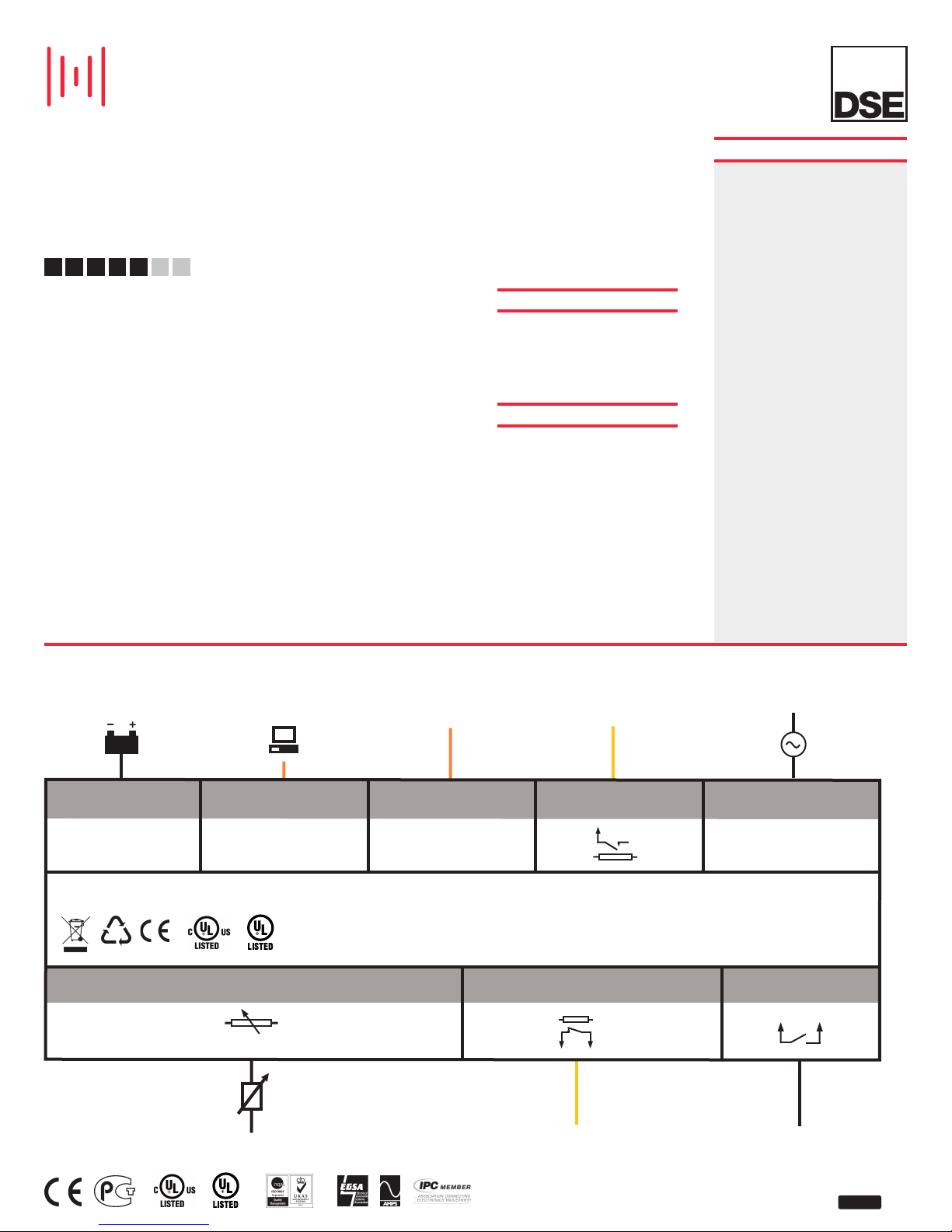
COMPREHENSIVE FEATURE LIST TO SUIT A WIDE VARIETY OF
BATTERY CHARGER APPLICATIONS
CHARGE OUTPUT
USB PORT
RS485
AUXILIARY DC OUTPUT
DSE9460/DSE9461
TEMPERATURE SENSOR
PT1000 ONLY
CHANGE OVER VOLTS FREE FAULT
RELAY
12V
1ph
N
AC POWER SUPPLY
+
CONFIGURABLE INPUT
1
1
ISSUE 1
Page 48
DSE
DSE9460/9461
ENCLOSED INTELLIGENT BATTERY CHARGER
5 AMP & 10 AMP, 12 VOLT & 24 VOLT OPTIONS
FEATURES
ADVANCED FEATURES
• Intelligent two, three and four stage charging
profiles
• Configurable to suit most battery types
(12V/24V)
• Adjustable current limit
• Can be used as a battery charger, power supply
or both at the same time
• Automatic or Manual boost and storage charge
functions to help maintain battery condition
• Digital Microprocessor Technology
• Temperature compensation for battery charging
• Low Output Ripple and superb line regulation
• Available in two variants (LCD display or LCD
display & analogue meters)
• AC input Under voltage
• AC input Over voltage
• Battery charger output Over voltage
• Battery charger output Over current
• Battery temperature compensation with over
temperature protection
• Output short circuit and Inversion polarity with
auto recovery
• Automatic power de-rating at high ambient
temperatures
• Battery charger failure indication
Boosts and equalises cell charge improving
•
battery performance and life
•
Once the battery is fully charged the chargers
switch to Eco-Power to save energy
• Can be integrated into external systems through
MODBUS RTU using RS485
• Fully configurable via DSE Configuration Suite
PC Software
• External remote LCD option
KEY BENEFITS
• Fully flexible to maximise the life of the battery
• Suitable for a wide range of battery types
• Switched mode design
• Fault output
• Minimum 86% efficiency throughout full
operating range
• No external intervention for boost mode
• Multiple chargers can be linked together to
provide larger current output
• Can be permanently connected to battery and
mains (utility) supply. No need to disconnect
through high load conditions.
SPECIFICATION
AC SUPPLY
VOLTAGE RANGE
90 V to 305 V (L-N)
FREQUENCY RANGE
48 Hz to 64 Hz (L-N)
DC OUTPUT RATING
DSE9460 OUTPUT
5 A DC at 12 V & 24 V DC
DSE9461 OUTPUT
10 A DC at 12 V & 24 V DC
RIPPLE AND NOISE
<1%
EFFICIENCY
>86%
AUXILIARY OUTPUT
100 mA DC at 12 V
REGULATION
LINE
<0.5%
LOAD
2%
TEMPERATURE SENSOR INPUT
PT1000
PROTECTIONS
Short Circuit
DC Over Voltage
C Over Current
D
Reverse Polarity
Over Temperature
AC Under & Over Voltage
Battery Charger Failure
CHARGE FAILURE RELAY
3 A at 30 V DC volt free relay
DIMENSIONS
OVERALL
165 mm x 305 mm x 110 mm
6.5” x 12” x 4.3”
WEIGHT
2.3 kg
OPERATING TEMPERATURE RANGE
-30oC to +55oC
STORAGE TEMPERATURE RANGE
-40oC to +85oC
®
RELATED MATERIALS
TITLE PART NO’S
DSE9000 Configuration Suite PC Software Manual 057-159
DSE Configuration Suite Installation & Operator Manual 057-151
DSE9460/DSE9461 Series Installation Instructions 053-148
DSE9460/DSE9461 Series Operator Manual 057-176
DSE2541 Data Sheet 055-160
DSE2541 Installation Instructions 053-154
DEEP SEA ELECTRONICS PLC UK
Highfield House, Hunmanby Industrial Estate, Hunmanby YO14 0PH
TELEPHONE +44 (0) 1723 890099 FACSIMILE +44 (0) 1723 893303
EMAIL [email protected] WEBSITE www.deepseaplc.com
Deep Sea Electronics Plc maintains a policy of continuous development and reserves the right to change
the details shown on this data sheet without prior notice. The contents are intended for guidance only.
DEEP SEA ELECTRONICS INC USA
3230 Williams Avenue, Rockford, IL 61101-2668 USA
TELEPHONE +1 (815) 316 8706 FACSIMILE +1 (815) 316 8708
EMAIL [email protected] WEBSITE www.deepseausa.com
Registered in England & Wales No.01319649
VAT No.316923457
055-153/11/12 US (4)
Page 49
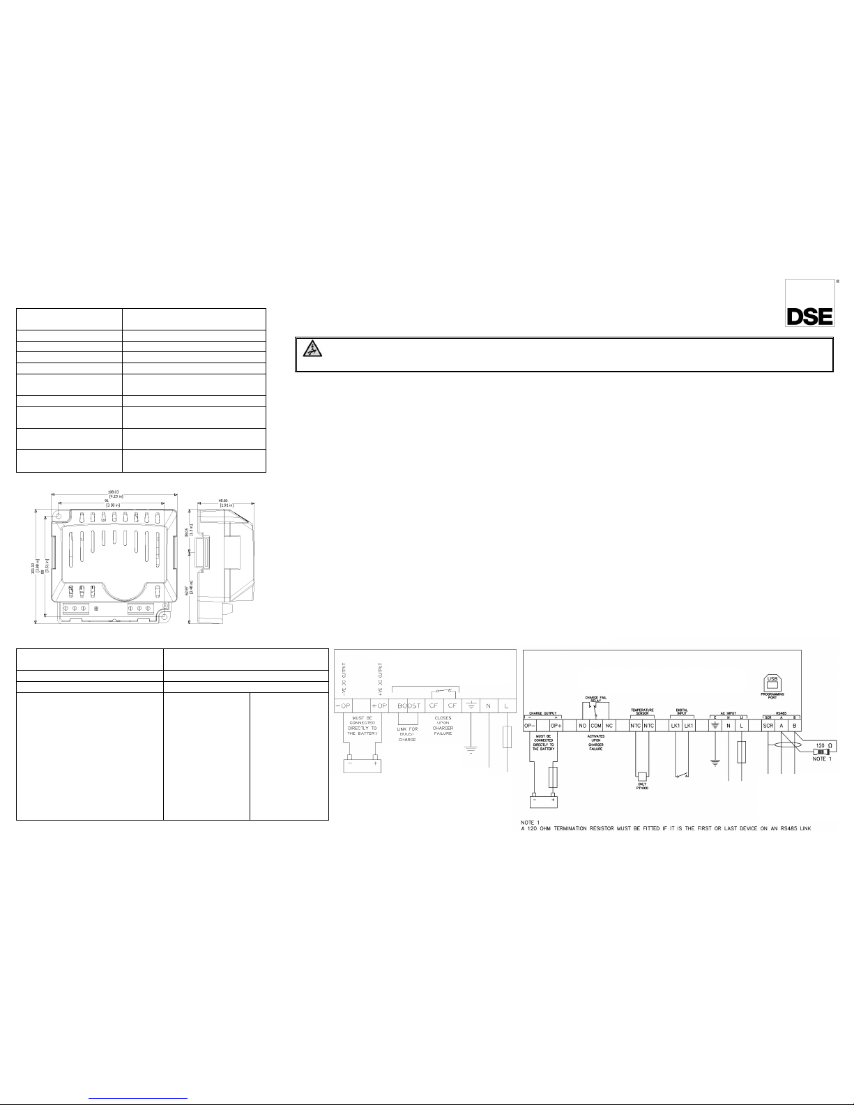
Typical Wiring Diagrams
053-049
ISSUE 13
DSE9xxx Battery Charger Installation Instructions
DEEP SEA ELECTRONICS
DANGER OF DEATH : LIVE PARTS exist within the DSE9xxx enclosures. The enclosure
cover must not
be removed.
Installation
The DSE9xxx battery chargers are designed to be mounted wi thin a control panel, on th e pan el DI N ra il utilising the integral mounts
or on a chassis utilising the mounting holes. For dimension and mounting details, see overleaf.
The DSE9xxx battery chargers are fit-and-forget. It can be permanently connected to the supply and the load, with no requirement to
disable the charger during times of heavy load (such as engine cranking) or when in parallel with a charging alternator.
Battery suitability
The charger is factory set by DSE to suit Lead Acid batteries. The DSE91xx & DSE92xx battery chargers can be adjusted at the time
of ordering to suit other battery types. The DSE947x MKII & DSE948x MKII battery char gers are configured using the DSE
Configuraiton Suite to suit other battery types.
Care should be taken to ensure the batteries connected to the charger are of the correct ‘technology’ to suit the setting of the
charger.
Indications
The DSE9xxx Battery Chargers feature an LED indicator(s) to show the battery charger Status.
(Refer to DSE publication: 057-085 DSE9xxx Series Operator Manual for further information)
Boost Mode
(Not applicable to DSE9150 12V 2A or DSE9155 30V 2A)
(DSE947x & DSE948x MKII Series Only. Boost feature is controlled automatically, no external connection needed.)
Boost mode is operated by connecting the BOOST terminals together (for instance with an external switch or timer circuit. This will
raise the battery charger floating voltage by 0.8V DC.
Caution:- Boost mode is intended for equalisation of cells in lead acid batteries.
Dimensions and Mounting
DSE9150 12V 3A
Overall size 108mm x 101mm x 49mm
(4.25” x 3.98” x 1.91”)
Weight 0.16kg
Mounting type DIN rail or chassis mounting
Din rail type EN 50022 35mm type only
Mounting holes Suitable for M4
Mounting hole centr es 91mm x 89mm
(4.25” x 3.51”)
Input voltage (nominal) 110V-240V
Input voltage (absolute
range)
90V-250V
Charge failure relay
rating
3A DC resistive, 30V maximum
Operating Temperature
-30°C to 55°C
(-22°F to 13 1°F)
Dime nsions i n mm u nless s tated
Connection type Screw terminal, rising clamp, no
internal spring
Min cabl e size 0.5mm² (AWG 20)
Max cable size 2.5mm² (AWG 14)
Recommended AC fuse
230V AC Input
110V AC Input
DSE9130 12V 5A charger
DSE9140 12V 10A charger
DSE9150 12V 3A charger
DSE9155 30V 2A charger
DSE9250 24V 3.7A charger
DSE9255 24V 5A charger
DSE9260 24V 10A charger
DSE9470 MKII 24V 10A charger
DSE9472 MKII 24V 5A charger
DSE9480 MKII 12V 10A charger
DSE9481 MKII 12V 5A charger
1.0A anti-surge
2.0A anti-surge
1.0A anti-surge
1.0A anti-surge
1.0A anti-surge
2.0A anti-surge
3.5A anti-surge
3.5A anti-surge
2.0A antisurge
2.0A anti-surge
1.0A antisurge
2.0A anti-surge
3.5A anti-surge
1.5A anti-surge
2.5A anti-surge
2.5A anti-surge
3.5A anti-surge
6.3A anti-surge
6.3A anti-surge
3.5A anti-surge
3.5A anti-surge
2.5A anti-surge
Boost not a vailable on
DSE9150 12V 3A
DSE9155 30V 2A
CF not available on
DSE9150 12V 2A
DSE 947x & 948x MKII Battery Chargers
DSE 91xx & 92xx Series
Battery Chargers
Page 50
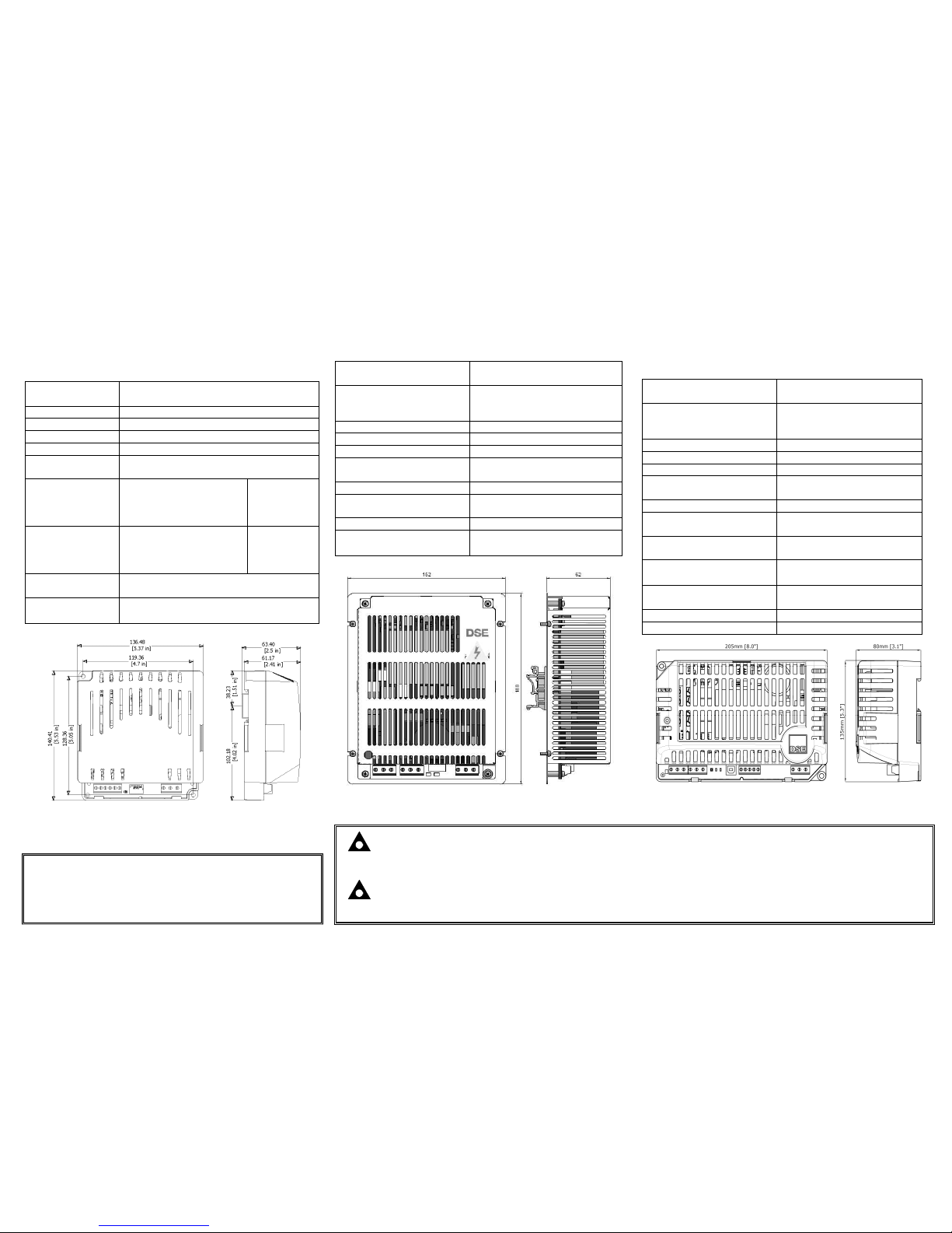
NOTE : DSE9000 series chargers are designed to be mounted with the base to a vertical surface with
the terminal strips at the bottom.
NOTE : This document is intended as a ‘quick start’ guide only. For full operating instructions and
specifications, refer to DSE publication: 057-085 DSE9xxx Series Operator Manual
Dimensions and Mounting
DSE9130 12V 5A DSE9250 24V 3.7A *
DSE9155 30V 2A DSE9255 24V 5A
* This model is no longer available
Overall size 136mm x 140mm x 63mm
(5.37” x 5.53” x 2.5”)
Weight 0.5kg
Mounting type DIN r ail or chassis mounting
Din rail type EN 50022 35mm type only
Mounting holes Suitable for M4
Mounting hole
centres
119.36mm x 128.36mm
(4.7” x 5.05”)
Input voltage
(nominal)
DSE9250-001 24V 3.7A
DSE9250-002 24V 3.7A
DSE9130 12V 5A
DSE9255 24V 5A
110V-240V
110V-277V
110V-277V
110V-277V
Input voltage
(absolute range)
DSE9250-001 24V 3.7A
DSE9250-002 24V 3.7A
DSE9130 12V 5A
DSE9255 24V 5A
90V-265V
90V-305V
90V-305V
90V-305V
Charge failure
relay rating
3A DC resistive, 30V maximum
Operating
Temperature
-30
°
C to 55°C
(-22°F to 131°F)
Dimensions in mm unless stated
Dimensions and Mounting
DSE9140 12V 10A
DSE9260 24V 10A
Overall size 152mm x 188mm x 62mm
(6” x 7.4”x 2.44”)
Weight
DSE9140 12V 10A
DSE9260 24V 10A
0.75kg
0.85kg
Mounting type DIN rail or chassis mounting
Din rail type EN 50022 35mm type only
Mounting holes Suitable for M4
Mounting hole centr es 142mm x 128mm
(5.59” x 5.0”)
Input voltage (nominal) 110V-277V
Input voltage
(absolute range)
90V-305V
Charge failure relay rating 3A DC resistive 30V Maximum
Operating Temperature
-30
°
C to 55°C
(-22°F to 131°F)
Dimensions in mm unless stated
Deep Sea Electronics Plc.
Tel:+44 (0)1723 890099
Fax: +44 (0)1723 893303
Email: [email protected] om
Web: www.deepseaplc.com
Deep Sea Electronics Inc.
Phone: +1 (815) 316-8706
Fax: +1 (815) 316- 8708
Email: sales@deepseaus a.com
Web: www.deepseausa.com
Dimensions and Mounting
Intelligent Battery Chargers
DSE9481 MKII 12V 5A
DSE9472 MKII 24V 5A
DSE9480 MKII 12V 10A
DSE9470 MKII 24V 10A
Overall size 205mm x 135mm x 80mm
(8.1” x 5.3” x 3.1”)
Weight
DSE9470 MKII
DSE9472/80/81 MKII
0.78kg
0.7kg
Mounting type DIN rail or chassis mounting
Din rail type EN 50022 35mm type only
Mounting holes Suitable for M4
Mounting hole centr es 190mm x 120mm
(7.5” x 4.7”)
Input voltage (nominal) 110V-277V
Input voltage
(absolute range)
95V-305V
Charge failure relay rating 3A DC resistive
30V maximum
Operating Temperature
-30
°
C to 85°C with de-rating
(-22°F to 185°F)
Optional Temperature
Sensor
NTC connections for PT1000
sensor only
Communications RS485
PC connection (USB) To enable PC Configuration
Dimensions in mm unless stated
6in
2.44in
7.4 in
 Loading...